US6029632A - Fuel injector with magnetic valve control for a multicylinder internal combustion engine with direct fuel injection - Google Patents
Fuel injector with magnetic valve control for a multicylinder internal combustion engine with direct fuel injection Download PDFInfo
- Publication number
- US6029632A US6029632A US09/120,147 US12014798A US6029632A US 6029632 A US6029632 A US 6029632A US 12014798 A US12014798 A US 12014798A US 6029632 A US6029632 A US 6029632A
- Authority
- US
- United States
- Prior art keywords
- valve body
- fuel
- valve
- annular
- control piston
- Prior art date
- Legal status (The legal status is an assumption and is not a legal conclusion. Google has not performed a legal analysis and makes no representation as to the accuracy of the status listed.)
- Expired - Fee Related
Links
Images

Classifications
-
- F—MECHANICAL ENGINEERING; LIGHTING; HEATING; WEAPONS; BLASTING
- F02—COMBUSTION ENGINES; HOT-GAS OR COMBUSTION-PRODUCT ENGINE PLANTS
- F02M—SUPPLYING COMBUSTION ENGINES IN GENERAL WITH COMBUSTIBLE MIXTURES OR CONSTITUENTS THEREOF
- F02M63/00—Other fuel-injection apparatus having pertinent characteristics not provided for in groups F02M39/00 - F02M57/00 or F02M67/00; Details, component parts, or accessories of fuel-injection apparatus, not provided for in, or of interest apart from, the apparatus of groups F02M39/00 - F02M61/00 or F02M67/00; Combination of fuel pump with other devices, e.g. lubricating oil pump
- F02M63/0003—Fuel-injection apparatus having a cyclically-operated valve for connecting a pressure source, e.g. constant pressure pump or accumulator, to an injection valve held closed mechanically, e.g. by springs, and automatically opened by fuel pressure
- F02M63/0007—Fuel-injection apparatus having a cyclically-operated valve for connecting a pressure source, e.g. constant pressure pump or accumulator, to an injection valve held closed mechanically, e.g. by springs, and automatically opened by fuel pressure using electrically actuated valves
-
- F—MECHANICAL ENGINEERING; LIGHTING; HEATING; WEAPONS; BLASTING
- F02—COMBUSTION ENGINES; HOT-GAS OR COMBUSTION-PRODUCT ENGINE PLANTS
- F02M—SUPPLYING COMBUSTION ENGINES IN GENERAL WITH COMBUSTIBLE MIXTURES OR CONSTITUENTS THEREOF
- F02M63/00—Other fuel-injection apparatus having pertinent characteristics not provided for in groups F02M39/00 - F02M57/00 or F02M67/00; Details, component parts, or accessories of fuel-injection apparatus, not provided for in, or of interest apart from, the apparatus of groups F02M39/00 - F02M61/00 or F02M67/00; Combination of fuel pump with other devices, e.g. lubricating oil pump
- F02M63/0003—Fuel-injection apparatus having a cyclically-operated valve for connecting a pressure source, e.g. constant pressure pump or accumulator, to an injection valve held closed mechanically, e.g. by springs, and automatically opened by fuel pressure
- F02M63/0005—Fuel-injection apparatus having a cyclically-operated valve for connecting a pressure source, e.g. constant pressure pump or accumulator, to an injection valve held closed mechanically, e.g. by springs, and automatically opened by fuel pressure using valves actuated by fluid pressure
Definitions
- the invention relates to a magnetic valve controlled fuel injector for a multi-cylinder internal combustion engine with direct fuel injection.
- the fuel injector includes in an injector housing a control piston and a valve body cooperating with the control piston.
- a high pressure line extends to the valve body and is, when the valve body is open, in communication with a fuel supply line which leads to a pressure chamber surrounding an injection nozzle valve needle.
- a passage extends through the control piston and the valve body by way of which a control space delimited by the control piston is constantly in communication with the high pressure line by way of a throttle structure. The pressure in the control space can be released by the magnetic valve to control the injection.
- a fuel return line is provided which also includes a throttle structure.
- Such a magnetic valve controlled fuel injector is known from DE 196 12 738 A1, wherein the control piston with an integrated valve body is guided in two housing parts and has a backside which is in direct contact with the nozzle needle: the valve body is surrounded by an annular space to which a fuel admission line leads and to which also a throttled return line to a low pressure fuel storage is connected.
- the high pressure line leading to the injection nozzle is pressure-relieved by the throttled return line, that is by the constant communication path between the supply line by way of the annular space and the low pressure return line.
- a fuel injector for direct fuel injection into a cylinder of an internal combustion engine under the control of an electromagnetic valve, with an injector housing having a control piston and a valve body disposed in a cylindrical opening in the injector housing whereby the high pressure fuel supply to a nozzle needle valve at one end of the injector is controlled, the valve body forms a valve whose downstream end is in communication, by way of a throttle structure, with a low pressure return line, the discharge of fuel from the downstream end of the valve body to the fuel return line being further controlled such that fuel can be discharged to the fuel return line only when the nozzle needle valve is closed.
- the release of high pressure fuel from the high pressure fuel chamber is interrupted since the communication between the supply line leading to the injection nozzle and the return line which is in communication with the low pressure system is controllable such that pressure relief occurs only between injections, but not while injection takes place. Consequently, the return fuel flow is substantially decreased.
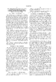
- FIG. 1 is a longitudinal cross-sectional view of the fuel injector according to the invention
- FIG. 2 is an enlarged cross-sectional view of the upper area of the fuel injector
- FIG. 3 is an enlarged cross-sectional view of the upper area of the injector showing another embodiment.
- a magnetic valve-controlled fuel injector 1 for direct fuel injection as it is used preferably in connection with storage injection systems operating according to the common rail principle employed in multi-cylinder internal combustion engines includes a multi-port injector housing 2 having a stepped cylindrical opening 3, a control piston 4 axially movably disposed in the cylindrical opening 3 and a valve body 5 cooperating with the control piston 4. It further includes a spring-loaded nozzle needle 6 spatially separated from valve body 5 and the control piston 4.
- the valve body 5 is in the form of a valve piston and is arranged co-axially with the control piston 4 of somewhat greater diameter.
- the control piston 4 includes an axial passage 7 which is in alignment with an axial passage 8 formed in the valve body 5.
- the control piston 4 and the valve body 5 are both disposed in a single housing part of the injector housing 2.
- the control piston 4 delimits at its top end face a control chamber 9 with which the axial passage 7 is in communication by way of a throttle structure 10. With this throttle structure 10, a higher pressure will be established at the high pressure end of the control piston than in the control chamber 9 when the pressure is released from the control chamber 9 so that the valve body 5 is lifted off the valve seat 12.
- the control chamber 9 is, by way of the coaxial passages 7, 8, in communication with a high pressure fuel supply line 11 extending radially in the injector housing 2.
- the valve body 5 includes a seating surface 13 corresponding to the conical valve seat 12 in the valve housing 2.
- the seating surface 13 is formed on a cylindrical lug 14, which projects axially from the valve body 5 and has a diameter smaller than the valve body 5 so that an annular space 15 is formed around the lug 14 from which a fuel supply passage 16 extends to a pressure chamber 17 formed around the spring-loaded nozzle needle 6.
- the annular control space 20 is in communication with a fuel return line 22 by way of the annular chamber 21 formed between the control piston 4 and the valve body 5.
- the annular chamber 21 is formed by an annular recess 24 in the valve body 5 and a similar annular recess 23 formed in the control piston 4, the annular chamber 21 being substantially larger than the annular control space 20.
- valve body 5 As soon as the pressure is released from the control chamber 9 by way of a pressure relief passage 25 by activation of the magnetic valve 26 (FIG. 1), the valve body 5 is lifted off the valve seat 12 by the higher pressure effective at the cylindrical lug 14 of the valve body 5 and the throttle structure 19 is closed by the control edge 20a whereby communication of the fuel supply passage 16 with the fuel return passage 25 is interrupted during fuel injection.
- the annular chamber 21 is in constant communication with the fuel return passage 25 independently of the position of the valve body 5--in contrast to the fuel supply passage 16 whose communication with the fuel return line 22 is interrupted when the valve body 5 is lifted during fuel injection.
- the throttle structure 19 does not need to be disposed in the injector housing 2 but may be disposed in the control piston 4 and is in communication with the annular chamber 21 by way of a longitudinal bore 27 extending through the valve body 5.
- the throttle structure 19 as shown in FIG. 3 extends radially through the valve body 5 at a small distance from the cylindrical lug 14 and the annular space 15 is extended axially such that the throttle structure is in communication with the annular space 15 when the valve body 5 is seated.
- the opening 19a of the throttle structure 19 is disposed at the upper edge of the annular space 15 such that communication between the annular space 15 and the fuel return line through the throttle structure 19 is interrupted as soon as the valve body 5 is lifted off the valve seat 12.
Landscapes
- Engineering & Computer Science (AREA)
- Chemical & Material Sciences (AREA)
- Combustion & Propulsion (AREA)
- Mechanical Engineering (AREA)
- General Engineering & Computer Science (AREA)
- Physics & Mathematics (AREA)
- Fluid Mechanics (AREA)
- Fuel-Injection Apparatus (AREA)
Abstract
Description
Claims (6)
Priority Applications (1)
| Application Number | Priority Date | Filing Date | Title |
|---|---|---|---|
| US09/120,147 US6029632A (en) | 1998-07-21 | 1998-07-21 | Fuel injector with magnetic valve control for a multicylinder internal combustion engine with direct fuel injection |
Applications Claiming Priority (1)
| Application Number | Priority Date | Filing Date | Title |
|---|---|---|---|
| US09/120,147 US6029632A (en) | 1998-07-21 | 1998-07-21 | Fuel injector with magnetic valve control for a multicylinder internal combustion engine with direct fuel injection |
Publications (1)
| Publication Number | Publication Date |
|---|---|
| US6029632A true US6029632A (en) | 2000-02-29 |
Family
ID=22388531
Family Applications (1)
| Application Number | Title | Priority Date | Filing Date |
|---|---|---|---|
| US09/120,147 Expired - Fee Related US6029632A (en) | 1998-07-21 | 1998-07-21 | Fuel injector with magnetic valve control for a multicylinder internal combustion engine with direct fuel injection |
Country Status (1)
| Country | Link |
|---|---|
| US (1) | US6029632A (en) |
Cited By (16)
| Publication number | Priority date | Publication date | Assignee | Title |
|---|---|---|---|---|
| FR2766523A1 (en) * | 1997-07-25 | 1999-01-29 | Daimler Benz Ag | FUEL INJECTION VALVE WITH DIRECT INJECTION AND ELECTROVALVE CONTROL FOR MULTI-CYLINDER ENGINE |
| US6308689B1 (en) * | 1999-03-10 | 2001-10-30 | Siemens Aktiengesellschaft | Injection valve for an internal combustion engine |
| FR2811024A1 (en) * | 2000-06-29 | 2002-01-04 | Bosch Gmbh Robert | INJECTOR HAVING A CONTROL SIDE OF THE OUTPUT SIDE |
| DE10033428A1 (en) * | 2000-07-10 | 2002-01-24 | Bosch Gmbh Robert | Pressure controlled injector for injecting fuel |
| US20020053340A1 (en) * | 1998-10-16 | 2002-05-09 | Ning Lei | Fuel injector with controlled high pressure fuel passage |
| US6460515B2 (en) * | 1998-10-22 | 2002-10-08 | Lucas Industries Limited | Fuel system |
| WO2002092994A1 (en) * | 2001-05-14 | 2002-11-21 | Wärtsilä Finland Oy | Fuel injection arrangement |
| US6484697B2 (en) * | 2000-06-29 | 2002-11-26 | Robert Bosch Gmbh | Pressure-controlled control part for common-rail injectors |
| US6616064B2 (en) * | 2000-06-29 | 2003-09-09 | Robert Bosch Gmbh | Injector with a control face on the outlet side |
| US6824081B2 (en) | 2002-06-28 | 2004-11-30 | Cummins Inc. | Needle controlled fuel injector with two control valves |
| US20060202139A1 (en) * | 2003-07-30 | 2006-09-14 | Hans-Christoph Magel | Control valve with pressure compensation for a fuel injector comprising a pressure intensifier |
| WO2006095143A1 (en) * | 2005-03-09 | 2006-09-14 | Delphi Technologies, Inc. | Valve arrangement |
| US7111614B1 (en) * | 2005-08-29 | 2006-09-26 | Caterpillar Inc. | Single fluid injector with rate shaping capability |
| EP1826397A2 (en) * | 2002-05-03 | 2007-08-29 | Delphi Technologies, Inc. | Fuel injection system |
| US20080022974A1 (en) * | 2006-07-28 | 2008-01-31 | Caterpillar Inc. | Multi-stage relief valve having different opening pressures |
| US20120006301A1 (en) * | 2009-03-17 | 2012-01-12 | Robert Bosch Gmbh | Apparatus for injecting fuel into the combustion chamber of an internal combustion engine |
Citations (11)
| Publication number | Priority date | Publication date | Assignee | Title |
|---|---|---|---|---|
| US4566416A (en) * | 1981-07-31 | 1986-01-28 | Stanadyne, Inc. | Accumulator nozzle fuel injection system |
| US5076241A (en) * | 1988-09-21 | 1991-12-31 | Toyota Jidosha Kabushiki Kaisha | Fuel injection device |
| US5347970A (en) * | 1992-12-23 | 1994-09-20 | Robert Bosch Gmbh | Fuel injection device for internal combustion engines |
| DE4341546A1 (en) * | 1993-12-07 | 1995-06-08 | Bosch Gmbh Robert | Fuel injection device for internal combustion engines |
| US5526791A (en) * | 1995-06-07 | 1996-06-18 | Diesel Technology Company | High-pressure electromagnetic fuel injector |
| DE19612738A1 (en) * | 1995-04-05 | 1996-10-10 | Avl Verbrennungskraft Messtech | Fuel injection system for IC engine |
| DE19621583A1 (en) * | 1995-06-06 | 1997-01-02 | Avl Verbrennungskraft Messtech | Diesel engine fuel injection system |
| US5605134A (en) * | 1995-04-13 | 1997-02-25 | Martin; Tiby M. | High pressure electronic common rail fuel injector and method of controlling a fuel injection event |
| US5662087A (en) * | 1995-03-20 | 1997-09-02 | AVL Gesellschaft fur Verbrennungskraftmaschinen und Messtechnik m.b.H. Prof.Dr.Dr.h.c. Hans List | Injection device for an internal combustion engine with direct injection |
| GB2322414A (en) * | 1997-02-19 | 1998-08-26 | Daimler Benz Ag | Common rail system for a multi-cylinder internal combustion engine having solenoid valve-controlled fuel injection valves |
| GB2322415A (en) * | 1997-02-19 | 1998-08-26 | Daimler Benz Ag | Common rail system for a multi-cylinder internal combustion engine |
-
1998
- 1998-07-21 US US09/120,147 patent/US6029632A/en not_active Expired - Fee Related
Patent Citations (11)
| Publication number | Priority date | Publication date | Assignee | Title |
|---|---|---|---|---|
| US4566416A (en) * | 1981-07-31 | 1986-01-28 | Stanadyne, Inc. | Accumulator nozzle fuel injection system |
| US5076241A (en) * | 1988-09-21 | 1991-12-31 | Toyota Jidosha Kabushiki Kaisha | Fuel injection device |
| US5347970A (en) * | 1992-12-23 | 1994-09-20 | Robert Bosch Gmbh | Fuel injection device for internal combustion engines |
| DE4341546A1 (en) * | 1993-12-07 | 1995-06-08 | Bosch Gmbh Robert | Fuel injection device for internal combustion engines |
| US5662087A (en) * | 1995-03-20 | 1997-09-02 | AVL Gesellschaft fur Verbrennungskraftmaschinen und Messtechnik m.b.H. Prof.Dr.Dr.h.c. Hans List | Injection device for an internal combustion engine with direct injection |
| DE19612738A1 (en) * | 1995-04-05 | 1996-10-10 | Avl Verbrennungskraft Messtech | Fuel injection system for IC engine |
| US5605134A (en) * | 1995-04-13 | 1997-02-25 | Martin; Tiby M. | High pressure electronic common rail fuel injector and method of controlling a fuel injection event |
| DE19621583A1 (en) * | 1995-06-06 | 1997-01-02 | Avl Verbrennungskraft Messtech | Diesel engine fuel injection system |
| US5526791A (en) * | 1995-06-07 | 1996-06-18 | Diesel Technology Company | High-pressure electromagnetic fuel injector |
| GB2322414A (en) * | 1997-02-19 | 1998-08-26 | Daimler Benz Ag | Common rail system for a multi-cylinder internal combustion engine having solenoid valve-controlled fuel injection valves |
| GB2322415A (en) * | 1997-02-19 | 1998-08-26 | Daimler Benz Ag | Common rail system for a multi-cylinder internal combustion engine |
Cited By (28)
| Publication number | Priority date | Publication date | Assignee | Title |
|---|---|---|---|---|
| FR2766523A1 (en) * | 1997-07-25 | 1999-01-29 | Daimler Benz Ag | FUEL INJECTION VALVE WITH DIRECT INJECTION AND ELECTROVALVE CONTROL FOR MULTI-CYLINDER ENGINE |
| US20020053340A1 (en) * | 1998-10-16 | 2002-05-09 | Ning Lei | Fuel injector with controlled high pressure fuel passage |
| US6868831B2 (en) | 1998-10-16 | 2005-03-22 | International Engine Intellectual Property Company, Llc | Fuel injector with controlled high pressure fuel passage |
| US6460515B2 (en) * | 1998-10-22 | 2002-10-08 | Lucas Industries Limited | Fuel system |
| US6308689B1 (en) * | 1999-03-10 | 2001-10-30 | Siemens Aktiengesellschaft | Injection valve for an internal combustion engine |
| DE10031572A1 (en) * | 2000-06-29 | 2002-01-17 | Bosch Gmbh Robert | Motor vehicle internal combustion engine fuel injector has casing with valve slide having flow control groove formed on its front face |
| FR2811024A1 (en) * | 2000-06-29 | 2002-01-04 | Bosch Gmbh Robert | INJECTOR HAVING A CONTROL SIDE OF THE OUTPUT SIDE |
| US6484697B2 (en) * | 2000-06-29 | 2002-11-26 | Robert Bosch Gmbh | Pressure-controlled control part for common-rail injectors |
| US6616064B2 (en) * | 2000-06-29 | 2003-09-09 | Robert Bosch Gmbh | Injector with a control face on the outlet side |
| DE10033428C2 (en) * | 2000-07-10 | 2002-07-11 | Bosch Gmbh Robert | Pressure controlled injector for injecting fuel |
| DE10033428A1 (en) * | 2000-07-10 | 2002-01-24 | Bosch Gmbh Robert | Pressure controlled injector for injecting fuel |
| WO2002092994A1 (en) * | 2001-05-14 | 2002-11-21 | Wärtsilä Finland Oy | Fuel injection arrangement |
| US20040163625A1 (en) * | 2001-05-14 | 2004-08-26 | Kai Lehtonen | Fuel injector |
| US7083126B2 (en) | 2001-05-14 | 2006-08-01 | Wartsila Finland Oy | Fuel injection arrangement |
| WO2003044359A1 (en) * | 2001-11-15 | 2003-05-30 | International Engine Intellectual Property Company, Llc. | Fuel injector with controlled high pressure fuel passage |
| KR100941794B1 (en) * | 2001-11-15 | 2010-02-10 | 인터내셔널 엔진 인터렉츄얼 프로퍼티 캄파니, 엘엘씨 | Fuel injector with controlled high pressure fuel passage |
| EP1826397A2 (en) * | 2002-05-03 | 2007-08-29 | Delphi Technologies, Inc. | Fuel injection system |
| EP1826397A3 (en) * | 2002-05-03 | 2009-08-05 | Delphi Technologies, Inc. | Fuel injection system |
| US6824081B2 (en) | 2002-06-28 | 2004-11-30 | Cummins Inc. | Needle controlled fuel injector with two control valves |
| US20060202139A1 (en) * | 2003-07-30 | 2006-09-14 | Hans-Christoph Magel | Control valve with pressure compensation for a fuel injector comprising a pressure intensifier |
| US7316361B2 (en) * | 2003-07-30 | 2008-01-08 | Robert Bosch Gmbh | Control valve with pressure compensation for a fuel injector comprising a pressure intensifier |
| EP1707801A1 (en) * | 2005-03-09 | 2006-10-04 | Delphi Technologies, Inc. | Valve arrangement |
| US20080245904A1 (en) * | 2005-03-09 | 2008-10-09 | Anthony Harcombe | Valve Arrangement |
| WO2006095143A1 (en) * | 2005-03-09 | 2006-09-14 | Delphi Technologies, Inc. | Valve arrangement |
| US7111614B1 (en) * | 2005-08-29 | 2006-09-26 | Caterpillar Inc. | Single fluid injector with rate shaping capability |
| US20080022974A1 (en) * | 2006-07-28 | 2008-01-31 | Caterpillar Inc. | Multi-stage relief valve having different opening pressures |
| US20120006301A1 (en) * | 2009-03-17 | 2012-01-12 | Robert Bosch Gmbh | Apparatus for injecting fuel into the combustion chamber of an internal combustion engine |
| US8839765B2 (en) * | 2009-03-17 | 2014-09-23 | Robert Bosch Gmbh | Apparatus for injecting fuel into the combustion chamber of an internal combustion engine |
Similar Documents
| Publication | Publication Date | Title |
|---|---|---|
| US6024297A (en) | Fuel injector | |
| US6029632A (en) | Fuel injector with magnetic valve control for a multicylinder internal combustion engine with direct fuel injection | |
| EP0426205B1 (en) | Device for the control of electro-hydraulically actuated fuel injectors | |
| US4658824A (en) | Fuel-injection device for an internal-combustion engine | |
| US6145492A (en) | Control valve for a fuel injection valve | |
| US5984200A (en) | Fuel injection system for a multi-cylinder internal combustion engine with magnetic valve controlled fuel injectors | |
| US5941215A (en) | Fuel injection system for a multicylinder internal combustion engine | |
| US20090145404A1 (en) | Injector of a fuel injection system of an internal combustion engine | |
| US5524826A (en) | Fuel injection device for internal combustion engines | |
| US7866575B2 (en) | Pressure actuated fuel injector | |
| US5476245A (en) | Pressure-compensated solenoid valve | |
| US4909444A (en) | Poppet covered orifice fuel injection nozzle | |
| US6027047A (en) | Magnetic valve-controlled injector for a storage fuel injection system of a multi-cylinder internal combustion engine | |
| US6308689B1 (en) | Injection valve for an internal combustion engine | |
| US5904300A (en) | Fuel injector | |
| US7267096B2 (en) | Fuel injection device for an internal combustion engine | |
| US5950930A (en) | Fuel injection valve for internal combustion engines | |
| US5150684A (en) | High pressure fuel injection unit for engine | |
| US6575384B2 (en) | Fuel injector with a control rod controlled by the fuel pressure in a control chamber | |
| JPH07332192A (en) | Fuel feeder for engine | |
| US6732949B1 (en) | Fuel injection valve for internal combustion engines | |
| US6758417B2 (en) | Injector for a common rail fuel injection system, with shaping of the injection course | |
| US6637409B2 (en) | Fuel injection device for internal combustion engines | |
| US7347385B2 (en) | Fuel injection device with a 3-way control valve for configuring the injection process | |
| US5988533A (en) | Magnetic valve controlled fuel injector |
Legal Events
| Date | Code | Title | Description |
|---|---|---|---|
| AS | Assignment |
Owner name: DAIMLER-BENZ AG, GERMANY Free format text: ASSIGNMENT OF ASSIGNORS INTEREST;ASSIGNOR:AUGUSTIN, ULRICH;REEL/FRAME:009341/0792 Effective date: 19980707 |
|
| AS | Assignment |
Owner name: DAIMLERCHRYSLER AG, GERMANY Free format text: CHANGE OF NAME;ASSIGNOR:DAIMLER-BENZ A.G.;REEL/FRAME:010064/0647 Effective date: 19981221 |
|
| FEPP | Fee payment procedure |
Free format text: PAYOR NUMBER ASSIGNED (ORIGINAL EVENT CODE: ASPN); ENTITY STATUS OF PATENT OWNER: LARGE ENTITY |
|
| REMI | Maintenance fee reminder mailed | ||
| LAPS | Lapse for failure to pay maintenance fees | ||
| FP | Lapsed due to failure to pay maintenance fee |
Effective date: 20040229 |
|
| STCH | Information on status: patent discontinuation |
Free format text: PATENT EXPIRED DUE TO NONPAYMENT OF MAINTENANCE FEES UNDER 37 CFR 1.362 |