US6004696A - AG-perovskite cermets for thin film solid oxide fuel cell air-electrode applications - Google Patents

AG-perovskite cermets for thin film solid oxide fuel cell air-electrode applications Download PDF

Info

Publication number
US6004696A
US6004696A US08/408,953 US40895395A US6004696A US 6004696 A US6004696 A US 6004696A US 40895395 A US40895395 A US 40895395A US 6004696 A US6004696 A US 6004696A
Authority
US
United States
Prior art keywords
perovskite
cermet
lsc
air electrode
electrode
Prior art date
Legal status (The legal status is an assumption and is not a legal conclusion. Google has not performed a legal analysis and makes no representation as to the accuracy of the status listed.)
Expired - Fee Related
Application number
US08/408,953
Inventor
Scott Alexander Barnett
Li-Shun Wang
Current Assignee (The listed assignees may be inaccurate. Google has not performed a legal analysis and makes no representation or warranty as to the accuracy of the list.)
Northwestern University
Original Assignee
Northwestern University
Priority date (The priority date is an assumption and is not a legal conclusion. Google has not performed a legal analysis and makes no representation as to the accuracy of the date listed.)
Filing date
Publication date
Application filed by Northwestern University filed Critical Northwestern University
Priority to US08/408,953 priority Critical patent/US6004696A/en
Assigned to NORTHWESTERN UNIVERSITY reassignment NORTHWESTERN UNIVERSITY ASSIGNMENT OF ASSIGNORS INTEREST (SEE DOCUMENT FOR DETAILS). Assignors: BARNETT, SCOTT A., WANG, LI-SHIN
Assigned to NORTHWESTERN UNIVERSITY reassignment NORTHWESTERN UNIVERSITY ASSIGNMENT OF ASSIGNORS INTEREST (SEE DOCUMENT FOR DETAILS). Assignors: BARNETT, SCOTT A., WANG, Li-shun
Application granted granted Critical
Publication of US6004696A publication Critical patent/US6004696A/en
Anticipated expiration legal-status Critical
Expired - Fee Related legal-status Critical Current

Links

Images

Classifications

    • HELECTRICITY
    • H01ELECTRIC ELEMENTS
    • H01MPROCESSES OR MEANS, e.g. BATTERIES, FOR THE DIRECT CONVERSION OF CHEMICAL ENERGY INTO ELECTRICAL ENERGY
    • H01M4/00Electrodes
    • H01M4/86Inert electrodes with catalytic activity, e.g. for fuel cells
    • H01M4/90Selection of catalytic material
    • H01M4/9016Oxides, hydroxides or oxygenated metallic salts
    • H01M4/9025Oxides specially used in fuel cell operating at high temperature, e.g. SOFC
    • H01M4/9033Complex oxides, optionally doped, of the type M1MeO3, M1 being an alkaline earth metal or a rare earth, Me being a metal, e.g. perovskites
    • HELECTRICITY
    • H01ELECTRIC ELEMENTS
    • H01MPROCESSES OR MEANS, e.g. BATTERIES, FOR THE DIRECT CONVERSION OF CHEMICAL ENERGY INTO ELECTRICAL ENERGY
    • H01M4/00Electrodes
    • H01M4/86Inert electrodes with catalytic activity, e.g. for fuel cells
    • H01M4/8605Porous electrodes
    • H01M4/8621Porous electrodes containing only metallic or ceramic material, e.g. made by sintering or sputtering
    • HELECTRICITY
    • H01ELECTRIC ELEMENTS
    • H01MPROCESSES OR MEANS, e.g. BATTERIES, FOR THE DIRECT CONVERSION OF CHEMICAL ENERGY INTO ELECTRICAL ENERGY
    • H01M4/00Electrodes
    • H01M4/86Inert electrodes with catalytic activity, e.g. for fuel cells
    • H01M4/90Selection of catalytic material
    • H01M4/9041Metals or alloys
    • H01M4/905Metals or alloys specially used in fuel cell operating at high temperature, e.g. SOFC
    • H01M4/9066Metals or alloys specially used in fuel cell operating at high temperature, e.g. SOFC of metal-ceramic composites or mixtures, e.g. cermets
    • YGENERAL TAGGING OF NEW TECHNOLOGICAL DEVELOPMENTS; GENERAL TAGGING OF CROSS-SECTIONAL TECHNOLOGIES SPANNING OVER SEVERAL SECTIONS OF THE IPC; TECHNICAL SUBJECTS COVERED BY FORMER USPC CROSS-REFERENCE ART COLLECTIONS [XRACs] AND DIGESTS
    • Y02TECHNOLOGIES OR APPLICATIONS FOR MITIGATION OR ADAPTATION AGAINST CLIMATE CHANGE
    • Y02EREDUCTION OF GREENHOUSE GAS [GHG] EMISSIONS, RELATED TO ENERGY GENERATION, TRANSMISSION OR DISTRIBUTION
    • Y02E60/00Enabling technologies; Technologies with a potential or indirect contribution to GHG emissions mitigation
    • Y02E60/30Hydrogen technology
    • Y02E60/50Fuel cells

Definitions

  • This invention relates generally to thin film solid oxide fuel cells (SOFC's) and more particularly to the Ag-perovskite cermet air electrodes in SOFC's.
  • Solid oxide fuel cells generally comprise a solid electrolyte such as yttria stabilized zirconia (YSZ) with a positive air electrode on one surface of the electrolyte and a negative fuel electrode such as a cermet of nickel and stabilized zirconia on the other surface of the electrolyte.
  • YSZ yttria stabilized zirconia
  • the electrode and/or electrolyte compositions can be changed to provide improved catalytic performance.
  • (La,Sr)CoO 3 (LSC) air electrodes on YSZ have been shown to provide improved performance over (La,Sr)MnO 3 (LSM).
  • the addition of a thin interfacial layer of a second electrolyte, such as Y-doped Bi 2 O 3 (YSB), can also lower r i [5].
  • standard electrode-electrolyte combinations can be processed so as to maximize he three-phase boundary length.
  • Electrochemical vapor deposition has been used to deposit YSZ within porous LSM electrodes to increase the contact area. Another means for increasing the contact area is via the use of a cermet electrode, e.g. Pt-YSZ or Ag-YSZ, where the additional contact area is within the cermet.
  • Cermet electrodes can also provide lower resistivity than ceramic air electrodes, especially at low temperatures.
  • ⁇ values were ⁇ 30 times lower than those of LSC and LSM at 750° C.
  • Pt-LSM [7] for typical T c values of ⁇ 1000° C.
  • Ag is an excellent candidate for cermets using perovskite oxide because of its good catalytic activity, high electrical conductivity, and relatively low cost.
  • the file of this patent contains at least one drawing executed in color.
  • FIG. 1 shows a schematic drawing of the dual-target sputtering geometry used for cermet deposition.
  • FIG. 2 shows the sample geometry used for interfacial resistance measurements.
  • FIG. 4 shows a film stress S as a function of Ag volume fraction in the cermets.
  • FIG. 7 shows resistivity ⁇ as a function of f Ag measured at 750° C. Also shown is the resistivity predicted using the GEM fit, eq. [2].
  • FIG. 8 shows log ⁇ T plotted as a function of reciprocal temperature for pure LSC ( ⁇ ), for Ag-LSC films with 0.05 ( ⁇ ), 0.3 ( ⁇ ), and 0.62 ( ⁇ ), and pure Ag ( ⁇ ).
  • FIGS. 9A-D show complex impedance plots from Ag- and LSC-containing electrodes with different f Ag values on YSB electrolyte, measured in air at 750° C.
  • FIG. 10 depicts interfacial resistance versus f Ag of Ag-LSC and Ag-LSM electrodes with different f Ag values on YSB electrolytes, measured in air at 750° C.
  • FIG. 11 depicts interfacial resistance r i versus inverse temperature for various Ag- and LSC-containing electrodes on YSB electrodes.
  • FIG. 13 depicts oxygen-pressure dependence of the interfacial resistance r i for various Ag- and LSC-containing electrodes on YSB.
  • the lines have a slope given by r i ⁇ P -0 .5.
  • Cermet electrode films in accordance with this invention were deposited by dc magnetron sputtering in a cylindrical, 35 cm diameter, glass bell jar vacuum chamber that was described in more detail elsewhere [8].
  • the chamber was turbomolecular pumped and reached a base pressure of ⁇ 3 ⁇ 10 -6 Torr when the liquid-nitrogen trap was filled.
  • Two spaced planar magnetron sputter sources 11, 12 FIG. 1 were used, one with a 99.95% pure, 5-cm-diameter Ag target and the other with the LSC (or LSM) target.
  • the substrate plane 13 was parallel to the target surface plane, at a distance of 7.6 cm. The distance between the target centers was 10 cm.
  • Substrates were placed along a line above the centers of the sputtering targets, allowing a wide range of cermet compositions to be deposited in a single deposition, while the cermet compositions were constant to within 5% over the 1 cm sample size.
  • (La 0 .7 Sr 0 .3)CoO 3 and (La 0 .7 Sr 0 .3)MnO 3 perovskite targets were synthesized by standard ceramic processing or purchased from SSC, Inc. In the former case, starting powder materials were La 2 O 3 (99.99%), SrCO 3 (99.9%) and Co 3 O 4 (99.5%). The powders were weighed in the desired ratio, dissolved in acetone solution and mixed for about 1 h. Finally, the mixed powders were cold-pressed at 100 MPa and sintered at 1150° C. in air for 30h into discs 5 cm diameter and ⁇ 3 mm in thickness. The formation of the perovskite structure was confirmed by means of x-ray diffraction (XRD) analysis.
  • XRD x-ray diffraction
  • Films were deposited onto silica glass substrates except in cases where high temperature ( ⁇ 600° C.) experiments were to be carried out, in which case dense alumina or YSB (25 mol % Y 2 O 3 substrates were used.
  • Alumina and YSB substrates were polished using 1 ⁇ m diamond-embedded paste.
  • the polished substrates were ultrasonically cleaned in 1 H 3 PO 4 :1 H 2 O solution to remove surface contamination.
  • both kinds of substrates were successively rinsed in de-ionized water, ultrasonically cleaned in acetone and finally dried with dry nitrogen. The substrates were not intentionally heated, but the substrate temperature rose to ⁇ 70° C. during deposition under typical conditions.
  • the sputtering gas was 99.999% pure argon.
  • the argon pressure P was 10 mTorr, corresponding to an argon flow rate of 114 ml/min.
  • the Ag target the applied voltage was 300 V and the current was 0.05 A, while the LSC (or LSM) target was operated at 200 V and 0.5 A, respectively.
  • the targets Prior to film deposition, the targets were sputter cleaned for 10 mins with a shutter covering the substrates. New perovskite targets were also sputtered for several hours to reach a steady state condition prior to depositing films. While cracks formed in the LSC and LSM targets after the initial sputtering period, the discharge conditions, sputtering rates, and film purity remained unaffected. Table 1 summarizes the sputtering conditions. Some of the sputter-deposited films were annealed in air at 500-600° C. for 10h prior to characterization.
  • the film thicknesses were 0.5-5 ⁇ m, as measured by scanning a profilometer stylus across a step edge created by masking the substrate during deposition.
  • Film chemical compositions were measured using energy dispersive x-ray analysis (EDX). Film stresses were determined by measuring the curvature of the substrate before and after film deposition with a microstylus profilometer with a scan range of 1 cm. Morphology was analyzed using scanning electron microscopy (SEM) with chemical mapping. Crystal structure was determined using x-ray diffraction (XRD) in the ⁇ -2 ⁇ geometry with Cu K ⁇ radiation (40 kV-20 mA). Electrical resistivities were measured using a van der Pauw geometry with gold or silver wires connected to the sample using silver paste. Electrode polarization curves were measured using a potentiostat (EG&G model 273) connected to a personal computer for data storage and analysis.
  • EDX energy dispersive x-ray analysis
  • the film deposition rate from two targets agreed well with the superposition of the rates from individual targets, as shown previously for Ag-YSZ cermets [6].
  • the silver volume fraction f Ag as a function of substrate position x (FIG. 1) is shown in FIG. 3.
  • the composition estimated from the superposition of the deposition rates of Ag, R Ag , and LSC, R LSC , using the expression f Ag (x) R Ag (x)(R Ag (x)+R LSC (x)], is also plotted in FIG. 3.
  • the curves agreed within experimental accuracy, indicating that there was little cross-contamination between the targets. EDX measurements showed that the metal composition of the deposited perovskite phase was stoichiometric within the experimental error ( ⁇ 5%), and was not changed after annealing.
  • the films were deposited on 200- ⁇ m-thick glass substrates.
  • the film stress S was related to the deflection ⁇ f the substrate, measured between the substrate center and a distance D from the center, by the equation ##EQU1## where E it the Young's modulus of the substrate (69 GPa), t s is the substrate thickness t f is the film thickness and v is Poisson's ratio for the substrate (0.16).
  • S is plotted as a function of f Ag for Ag-LSC in FIG. 4.
  • the films were in a compressive stress state. S was largest for put LSC, 3.5 ⁇ 10 8 Pa, and decreased rapidly with increasing f Ag to 0.5 ⁇ 10 8 Pa for pure Ag.
  • the magnitude and sign of the stress are very similar to previous results for Ag-YSZ cermet films prepared using the same technique [6].
  • the lower stress in Ag-rich films was likely due to plastic deformation of Ag limiting the film stress to relatively low levels.
  • FIGS. 5A-D show representative x-ray diffraction (XRD) spectra from both as-deposited and annealed 1- ⁇ m-thick films with different f Ag .
  • the crystallinity of this sample improved after annealing at 500-600° C. for 10h (b) as indicated by the sharper, more-intense Ag peaks and the appearance of LSC peaks.
  • the relative Ag and perovskite peak intensities correlated well with the film composition.
  • FIG. 6B shows the EDX chemical image of the same film after annealing at 750° C. for 2h in air. The only change from the as-deposited film in FIG. 6A was the appearance of isolated Ag clusters.
  • the resistivity ⁇ of 1- ⁇ m-thick Ag-LSC films on alumina substrates versus f Ag , measured at temperature T 750° C. in air, is shown in FIG. 7.
  • the films had been annealed at 600° C. in air for 10h prior to measurement, and ⁇ values were stable during the measurement.
  • decreased with f Ag from 1.6 ⁇ 10 -2 ⁇ .cm for a pure perovskite film to 1 ⁇ 10 -5 ⁇ .cm for a pure Ag film.
  • the ⁇ variation with metal volume fraction was much stronger on the perovskite-rich side than that observed for Pt-LSM cermets [7].
  • ⁇ T for annealed films with different Ag-LSC compositions is plotted versus 1000/T in FIG. 8. Straight lines are observed over the whole temperature range, and the slope is consistent with a small-polaron conduction model for the LSC-rich compositions. With increasing Ag content, the slope decreases and eventually reverses, exhibiting the decrease in ⁇ expected for metals with increasing T.
  • the electrode interfacial resistance r 1 determined from the real-axis intercepts of the arcs as shown in FIGS. 9A-D, are plotted versus f Ag for both Ag-LSC ad Ag-LSM in FIG. 10.
  • the shape of the impedance arcs for Ag-LSM was similar to those shown for Ag-LSC.
  • the electrode resistances were limited primarily by mass transport, although charge transfer apparently became more important for the LSC-rich compositions.
  • the combination of two materials with different rate-limiting processes may allow a "short-circuiting" of the limiting steps of each.
  • Ag may provide sites for efficient charge transfer, while LSC may provide rapid mass transport.
  • the effective three-phase boundary length in the cermet may be larger due either to a composition-dependent change in electrode morphology or the additional Ag-LSC interfaces in the cermet.
  • Ag-perovskite cermets with f Ag in the range of 0.2-0.6 provide high conductivity and low interfacial resistance. Cermets with volume fraction of silver of about 0.3 are preferable because they combine high conductivity with low interface resistance.
  • This composition was thus tested in initial 200h stability tests in air at 750° C. Based upon prior experience with Ag-YSZ electrodes [5], the tests were conducted on electrodes that were coated with a 1 ⁇ m thick, pure porous LSC layer in order to suppress Ag evaporation and segregation.
  • the cap layer was effective in maintaining stable electrode morphology and composition, as indicated by SEM and EDX observations after annealing r i for 200 h at 750° C. were examined by ERD and showed no evidence of the formation of interfacial phases.
  • the resistivity of Ag-(La 0 .7 Sr 0 .3)CoO 3 cermets decreased as the Ag volume fraction f Ag increased from ⁇ 1.6 ⁇ 10 -2 ⁇ .cm for pure LSC to ⁇ 10 -5 ⁇ .cm for pure Ag at 740° C.
  • the cermet electrodes should thus allow either a decrease in electrode resistance, important to reduce ohmic polarization in cell geometries with long current paths, or a decrease in electrode thickness to reduce materials costs.
  • Ag-LSM electrodes also exhibited lower r i than either pure Ag or pure LSM on YSB electrolytes.
  • the cermet material has been described particularly with respect to SOFC's, the cermet is also useful for other solid-state electrochemical devices, e.g., sensors and electrolyzers.

Landscapes

  • Chemical & Material Sciences (AREA)
  • Engineering & Computer Science (AREA)
  • Chemical Kinetics & Catalysis (AREA)
  • Electrochemistry (AREA)
  • General Chemical & Material Sciences (AREA)
  • Materials Engineering (AREA)
  • Ceramic Engineering (AREA)
  • Inert Electrodes (AREA)

Abstract

An air electrode for a solid oxide fuel cell having high conductivity and low interfacial resistance is disclosed. Said air electrode is composed of an Ag-perovskite cermet.

Description

BRIEF DESCRIPTION OF THE INVENTION
This invention relates generally to thin film solid oxide fuel cells (SOFC's) and more particularly to the Ag-perovskite cermet air electrodes in SOFC's.
BACKGROUND OF THE INVENTION
Solid oxide fuel cells generally comprise a solid electrolyte such as yttria stabilized zirconia (YSZ) with a positive air electrode on one surface of the electrolyte and a negative fuel electrode such as a cermet of nickel and stabilized zirconia on the other surface of the electrolyte.
Results on solid oxide fuel cells (SOFC's) employing thin (˜10 μm) Y-stabilized zirconia (YSZ) electrolytes [1,2] have recently been reported. One of the main advantages of these thin-film-electrolyte cells is that electrolyte ohmic resistance is small even at reduced (600-800° C.) operating temperatures Tc [3]. Reduced SOFC temperatures should ease materials and processing problems associated with interconnection and gas sealing in SOFC stacks [4]. However, as Tc is lowered below the typical value of ≈1000° C., the rates of thermally-activated electrochemical reactions decrease, increasing electrode interfacial resistance ri and limiting the SOFC current density. In addition, the resistivity ρ of perovskite air electrode materials increases with decreasing temperature.
Two general approaches have been used to reduce ri. First, the electrode and/or electrolyte compositions can be changed to provide improved catalytic performance. For example, (La,Sr)CoO3 (LSC) air electrodes on YSZ have been shown to provide improved performance over (La,Sr)MnO3 (LSM). The addition of a thin interfacial layer of a second electrolyte, such as Y-doped Bi2 O3 (YSB), can also lower ri [5]. Second, standard electrode-electrolyte combinations can be processed so as to maximize he three-phase boundary length. Electrochemical vapor deposition has been used to deposit YSZ within porous LSM electrodes to increase the contact area. Another means for increasing the contact area is via the use of a cermet electrode, e.g. Pt-YSZ or Ag-YSZ, where the additional contact area is within the cermet.
Cermet electrodes can also provide lower resistivity than ceramic air electrodes, especially at low temperatures. For Ag-YSZ cermets[6], for example, ρ values were ≈30 times lower than those of LSC and LSM at 750° C. There has been relatively little work done on cermets that contain noble metals and perovskite oxides, with only one preliminary report on Pt-LSM [7] for typical Tc values of ≈1000° C. We have observed that for SOFC's with Tc<800° C. Ag is an excellent candidate for cermets using perovskite oxide because of its good catalytic activity, high electrical conductivity, and relatively low cost.
OBJECTS AND SUMMARY OF THE INVENTION
It is an object of this invention to provide an inexpensive air electrode for SOFC's which has good catalytic activity and high electrical conductivity.
It is another object of the invention to provide thin film Ag-perovskite cermets for use as positive air electrodes in SOFC's.
Pursuant to the invention there is provided a sputtered Ag-perovskite thin film air electrode for SOFC's.
BRIEF DESCRIPTION OF THE DRAWINGS
The file of this patent contains at least one drawing executed in color.
The foregoing and other objects of the invention will be more clearly understood from the following description, when read in conjunction with the accompanying drawings, wherein:
FIG. 1 shows a schematic drawing of the dual-target sputtering geometry used for cermet deposition.
FIG. 2 shows the sample geometry used for interfacial resistance measurements.
FIG. 3 shows an Ag volume fraction fAg, measured using EDX, as a function of substrate position. Also plotted is the volume fraction predicted using fAg =RAg /RAg+R LSC).
FIG. 4 shows a film stress S as a function of Ag volume fraction in the cermets.
FIGS. 5A-D show X-ray diffractometer scan from (a) an as-deposited fAg =0.5 Ag-LSC cermet, and from (b)fAg =0.5, (c)fAg =0.3, and (d) pure LSC films after annealing at 500-600° C. in air for 10h.
FIGS. 6A and 6B show SEM chemical images from (a) an as-deposited fAg =0.3 cermet film and (b) the same film after annealing at 750° C. in air for 2h.
FIG. 7 shows resistivity ρ as a function of fAg measured at 750° C. Also shown is the resistivity predicted using the GEM fit, eq. [2].
FIG. 8 shows logσT plotted as a function of reciprocal temperature for pure LSC (◯), for Ag-LSC films with 0.05 (□), 0.3 (), and 0.62 (▴), and pure Ag (⋄).
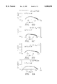
FIGS. 9A-D show complex impedance plots from Ag- and LSC-containing electrodes with different fAg values on YSB electrolyte, measured in air at 750° C.
FIG. 10 depicts interfacial resistance versus fAg of Ag-LSC and Ag-LSM electrodes with different fAg values on YSB electrolytes, measured in air at 750° C.
FIG. 11 depicts interfacial resistance ri versus inverse temperature for various Ag- and LSC-containing electrodes on YSB electrodes.
FIGS. 12A-D depict complex impedance plots from fAg =0.3 Ag-LSC electrodes on YSB electrolytes, measured at 750° C. for various oxygen partial pressures.
FIG. 13 depicts oxygen-pressure dependence of the interfacial resistance ri for various Ag- and LSC-containing electrodes on YSB. The lines have a slope given by ri αP-0.5.
DESCRIPTION OF THE PREFERRED EMBODIMENT
Cermet electrode films in accordance with this invention were deposited by dc magnetron sputtering in a cylindrical, 35 cm diameter, glass bell jar vacuum chamber that was described in more detail elsewhere [8]. The chamber was turbomolecular pumped and reached a base pressure of <3×10⁻⁶ Torr when the liquid-nitrogen trap was filled. Two spaced planar magnetron sputter sources 11, 12 FIG. 1 were used, one with a 99.95% pure, 5-cm-diameter Ag target and the other with the LSC (or LSM) target. The substrate plane 13 was parallel to the target surface plane, at a distance of 7.6 cm. The distance between the target centers was 10 cm. Substrates were placed along a line above the centers of the sputtering targets, allowing a wide range of cermet compositions to be deposited in a single deposition, while the cermet compositions were constant to within 5% over the 1 cm sample size.
(La0.7 Sr0.3)CoO3 and (La0.7 Sr0.3)MnO3 perovskite targets were synthesized by standard ceramic processing or purchased from SSC, Inc. In the former case, starting powder materials were La2 O3 (99.99%), SrCO3 (99.9%) and Co3 O4 (99.5%). The powders were weighed in the desired ratio, dissolved in acetone solution and mixed for about 1 h. Finally, the mixed powders were cold-pressed at 100 MPa and sintered at 1150° C. in air for 30h into discs 5 cm diameter and ≈3 mm in thickness. The formation of the perovskite structure was confirmed by means of x-ray diffraction (XRD) analysis. Energy dispersive x-ray analysis (EDX) showed the LSC and LSM targets to have the desired metal compositions, i.e. 30 mol % Sr on the A site and stoichiometry between the A and B sites. The commercial perovskite powders were cold pressed at 25 MPa and sintered in air at 1150° C. for 10 h. No difference was observed in the results for the two different methods of target preparation.
Films were deposited onto silica glass substrates except in cases where high temperature (≧600° C.) experiments were to be carried out, in which case dense alumina or YSB (25 mol % Y2 O3 substrates were used. Alumina and YSB substrates were polished using 1 μm diamond-embedded paste. The polished substrates were ultrasonically cleaned in 1 H3 PO4 :1 H2 O solution to remove surface contamination. Prior to film deposition, both kinds of substrates were successively rinsed in de-ionized water, ultrasonically cleaned in acetone and finally dried with dry nitrogen. The substrates were not intentionally heated, but the substrate temperature rose to ≈70° C. during deposition under typical conditions.
The sputtering gas was 99.999% pure argon. The argon pressure P was 10 mTorr, corresponding to an argon flow rate of 114 ml/min. For the Ag target, the applied voltage was 300 V and the current was 0.05 A, while the LSC (or LSM) target was operated at 200 V and 0.5 A, respectively. Prior to film deposition, the targets were sputter cleaned for 10 mins with a shutter covering the substrates. New perovskite targets were also sputtered for several hours to reach a steady state condition prior to depositing films. While cracks formed in the LSC and LSM targets after the initial sputtering period, the discharge conditions, sputtering rates, and film purity remained unaffected. Table 1 summarizes the sputtering conditions. Some of the sputter-deposited films were annealed in air at 500-600° C. for 10h prior to characterization.
              TABLE 1                                                     
______________________________________                                    
Ag-LSC-Co-Sputtering Conditions                                           
Targets           Ag     LSC                                              
______________________________________                                    
Voltage (V)       300    200                                              
Current (A)       0.05   0.5                                              
Sputter Gas              Ar(10 mTorr)                                     
Substrate Temperature    70° C.                                    
Deposition Rate          0.7-1.6 μm/h                                  
______________________________________                                    
The film thicknesses were 0.5-5 μm, as measured by scanning a profilometer stylus across a step edge created by masking the substrate during deposition. Film chemical compositions were measured using energy dispersive x-ray analysis (EDX). Film stresses were determined by measuring the curvature of the substrate before and after film deposition with a microstylus profilometer with a scan range of 1 cm. Morphology was analyzed using scanning electron microscopy (SEM) with chemical mapping. Crystal structure was determined using x-ray diffraction (XRD) in the θ-2θ geometry with Cu Kα radiation (40 kV-20 mA). Electrical resistivities were measured using a van der Pauw geometry with gold or silver wires connected to the sample using silver paste. Electrode polarization curves were measured using a potentiostat (EG&G model 273) connected to a personal computer for data storage and analysis.
Interfacial resistance of Ag-perovskite electrodes on (Y2 O3)0.25 (Bi2 O3)0.75 were studied using a Solartron SI 1260 Frequency Response Analyzer (FRA) over a frequency range 100 kHz to 10 mHz using a ±10 mV excitation signal. Two sample geometries were used. First, the 0.5-1.0 μm thick electrodes were deposited on both sides of a 2-mm-thick YSB ceramic. The area-specific resistance ri =Rc A, where A is the electrode area and Re is the measured resistance. Second, measurements were carried out between two electrodes deposited on 3-μm-thick YSB (25 mol % Y2 O3) electrolyte thin films on dense alumina substrates. The YSB was deposited by reactive co-sputtering from Y and Bi targets in Ar/O2 mixtures at a total pressure of 10 mTorr. The Ag-perovskite cermet electrodes (0.5-1.0 μm thick) were deposited through a mask that defined two symmetric rectangular regions (FIG. 2) on the YSB film, of width w=0.6-1.0 cm and length d2 =2.5 mm, separated by a distance d1 =0.4-0.6 mm. Comparisons of the two types of measurements gave excellent agreement.
The film deposition rate from two targets agreed well with the superposition of the rates from individual targets, as shown previously for Ag-YSZ cermets [6]. The silver volume fraction fAg as a function of substrate position x (FIG. 1) is shown in FIG. 3. The composition estimated from the superposition of the deposition rates of Ag, RAg, and LSC, RLSC, using the expression fAg (x)=RAg (x)(RAg (x)+RLSC (x)], is also plotted in FIG. 3. The curves agreed within experimental accuracy, indicating that there was little cross-contamination between the targets. EDX measurements showed that the metal composition of the deposited perovskite phase was stoichiometric within the experimental error (<5%), and was not changed after annealing.
Film densities were estimated by dividing the film mass, given by the mass difference before and after deposition, by the film volume, obtained from the film thickness and area. Because of the errors in these two measurements, the overall accuracy is 10%. For both pure Ag and cermet films with fAg =0.3, the density η relative to the theoretical value ηth is η/ηth ≈0.7.
For stress measurements, the films were deposited on 200-μm-thick glass substrates. The film stress S was related to the deflection δf the substrate, measured between the substrate center and a distance D from the center, by the equation ##EQU1## where E it the Young's modulus of the substrate (69 GPa), ts is the substrate thickness tf is the film thickness and v is Poisson's ratio for the substrate (0.16). S is plotted as a function of fAg for Ag-LSC in FIG. 4. The films were in a compressive stress state. S was largest for put LSC, 3.5×10⁸ Pa, and decreased rapidly with increasing fAg to 0.5×10⁸ Pa for pure Ag. The magnitude and sign of the stress are very similar to previous results for Ag-YSZ cermet films prepared using the same technique [6]. The lower stress in Ag-rich films was likely due to plastic deformation of Ag limiting the film stress to relatively low levels.
FIGS. 5A-D show representative x-ray diffraction (XRD) spectra from both as-deposited and annealed 1-μm-thick films with different fAg. The as-deposited fAg =0.5 cermet film (a) was partially amorphous as indicated by the lack of perovskite peaks, the weak broadened Ag peak intensities, and relatively large background intensity. The crystallinity of this sample improved after annealing at 500-600° C. for 10h (b) as indicated by the sharper, more-intense Ag peaks and the appearance of LSC peaks. XRD results from fAg =0.3(c) and fAg =0(d) films after annealing are also shown. The relative Ag and perovskite peak intensities correlated well with the film composition.
The Ag and perovskite distribution in the cermet films was assessed using SEM chemical imaging. FIG. 6A shows the chemical images of the spatially-resolved La, Sr, Co, and Ag EDX signals in an as-deposited fAg =0.3 Ag-LSC film deposited on an alumina substrate. La, Sr, Co, and Ag were uniformly dispersed, on the scale observed by SEM (≈0.1 μm), in the as-deposited film. FIG. 6B shows the EDX chemical image of the same film after annealing at 750° C. for 2h in air. The only change from the as-deposited film in FIG. 6A was the appearance of isolated Ag clusters. Segregation of the metal out of the cermet structure has also been observed for Ag-YSZ [6] and Ni-YSZ cermets after annealing. The segregation can be suppressed by the use of a pure LSC cap layer, as discussed below.
The resistivity ρ of 1-μm-thick Ag-LSC films on alumina substrates versus fAg, measured at temperature T=750° C. in air, is shown in FIG. 7. The films had been annealed at 600° C. in air for 10h prior to measurement, and ρ values were stable during the measurement. ρ decreased with fAg from 1.6×10⁻² Ω.cm for a pure perovskite film to 1×10⁻⁵ Ω.cm for a pure Ag film. The ρ variation with metal volume fraction was much stronger on the perovskite-rich side than that observed for Pt-LSM cermets [7]. However, the present resistivity values are in excellent agreement with the general effective media (GEM) theoretical predictions for cermets where both phases are conducting. The calculated cermet electrical conductivity σ is given by ##EQU2## where σAg and σLSC are the conductivities of the two phases, A=(1-fc)/fc, fc is the critical Ag volume fraction for percolation conductivity, and p is a parameter usually in the range from 1.65-2.0. The solid line shown in FIG. 6 was obtained using fc =0.4 and p=2.0, which are both reasonable values. The calculated curve is in good agreement with the data.
σT for annealed films with different Ag-LSC compositions is plotted versus 1000/T in FIG. 8. Straight lines are observed over the whole temperature range, and the slope is consistent with a small-polaron conduction model for the LSC-rich compositions. With increasing Ag content, the slope decreases and eventually reverses, exhibiting the decrease in σ expected for metals with increasing T.
Impedance spectroscopy studies of reactions at Ag-LSC electrodes on YSB were carried out as a function of T, oxygen partial pressure P, and fAg. FIGS. 9A-D show complex impedance plots for different electrode compositions on YSB electrolytes, measured at T=750° C. in air. The bulk arcs were omitted. The fAg =0, 0.3, and 0.5 results showed a superposition of two arcs, indicating that there was more than one important rate-limiting step. The lower-frequency arc became more important with increasing fAg.
The electrode interfacial resistance r1, determined from the real-axis intercepts of the arcs as shown in FIGS. 9A-D, are plotted versus fAg for both Ag-LSC ad Ag-LSM in FIG. 10. For Ag-LSC ri first decreased with increasing fAg, reached a minimum near fAg =0.3, and then increased rapidly to the value characteristic of pure Ag. The shape of the impedance arcs for Ag-LSM was similar to those shown for Ag-LSC. The ri value for pure LSM was almost a factor of two higher than that for pure LSC. Adding Ag to LSM decreased ri substantially, as shown for fAg =0.3 in FIG. 10.
FIG. 11 gives ri as a function of 1/T for Ag, LSC, and cermet electrodes with fAg =0.3 and 0.5. The fAg =0.3 composition showed the lowest interfacial resistance for T>550° C., while pure Ag had the lowest ri for T<550° C. The slope of logri versus 1/T was largest for fAg =0.3 (the corresponding activation energy was 105 kJ/mol), and was sightly smaller for both pure Ag, corresponding to 58 kJ/mol. The similar slopes for LSC and fAg =0.3 and 0.5 electrodes suggests that the rate-limiting steps were the same, although the fAg =0.3 cermet exhibited a lower absolute ri rate.
FIGS. 12A-D show the low-frequency impedance diagrams as a function of P for the fAg =0.3 cermet. Two overlapping electrode arcs were observed in each case, with the lower-frequency arc dominating at low P and the higher-frequency arc dominating at high P. FIG. 13 shows ri versus P for Ag, LSC, and fAg =0.3 electrodes obtained from data such as shown in FIGS. 12A-D. The Ag electrode exhibited a ri α P-0.5 dependence, indicative of mass transport as the rate-limiting step. Both the LSC and cermet electrodes exhibited a P-0.5 power law at intermediate P, but showed indications of a larger exponent at lower P and a smaller exponent at higher P. For electrode operation in air, the primary rate-limiting process was thus mass transport, although there were indications that charge transfer played a role. The P-dependencies for the LSC and fAg =0.3 electrodes were essentially the same, indicating similar reaction mechanisms in agreement with the temperature-dependent studies above.
The overpotential η of the fAg =0.3 electrode on YSB was measured with a potentiostat at T=750° C. in air. The low current resistance was very close to the value ri =0.3 Ωcm2 measured by impedance spectroscopy, but increased slightly with increasing current density to yield η≈35 mV at 100 mA/cm2.
To summarize the above results for T=750° C. in air, the electrode resistances were limited primarily by mass transport, although charge transfer apparently became more important for the LSC-rich compositions. Two possible explanations can be proposed for the decrease in ri as Ag is added to LSC, as shown in FIG. 10. First, the combination of two materials with different rate-limiting processes may allow a "short-circuiting" of the limiting steps of each. For example, Ag may provide sites for efficient charge transfer, while LSC may provide rapid mass transport. Second, the effective three-phase boundary length in the cermet may be larger due either to a composition-dependent change in electrode morphology or the additional Ag-LSC interfaces in the cermet.
Based on the above results, Ag-perovskite cermets with fAg in the range of 0.2-0.6 provide high conductivity and low interfacial resistance. Cermets with volume fraction of silver of about 0.3 are preferable because they combine high conductivity with low interface resistance.
This composition was thus tested in initial 200h stability tests in air at 750° C. Based upon prior experience with Ag-YSZ electrodes [5], the tests were conducted on electrodes that were coated with a 1 μm thick, pure porous LSC layer in order to suppress Ag evaporation and segregation. The cap layer was effective in maintaining stable electrode morphology and composition, as indicated by SEM and EDX observations after annealing ri for 200 h at 750° C. were examined by ERD and showed no evidence of the formation of interfacial phases.
The poor thermal expansion match between these materials and the electrolyte is a potential problem, especially for Ag-LSC. There was no evidence of cracking or delamination of the Ag-perovskite films despite numerous thermal cycles between room temperature and 750° C. This indicates that at a film thickness of 1 μm, the Ag and LSC thermal expansion difference with alumina and YSB substrates was not a major problem. Ag-perovskite films with thickness in the range of 1.5 to 100 μm are useful; however, Ag-perovskite films with thickness in the range of 10.5 to 1.5 μm are preferred, because that range minimizes the cracking problem.
The resistivity of Ag-(La0.7 Sr0.3)CoO3 cermets decreased as the Ag volume fraction fAg increased from ≈1.6×10⁻² Ω.cm for pure LSC to ≈10-5 Ω.cm for pure Ag at 740° C. The fAg =0.3 cermet had a resistivity factor of =20 times less than pure LSC. The cermet electrodes should thus allow either a decrease in electrode resistance, important to reduce ohmic polarization in cell geometries with long current paths, or a decrease in electrode thickness to reduce materials costs. The interfacial resistance ri of the cermet electrodes with fAg =0.3 on YSB electrolytes was 0.3 Ω.cm2 at 750° C. in air, lower than either pure LSC or pure Ag, and was stable during initial long-term testing. Ag-LSM electrodes also exhibited lower ri than either pure Ag or pure LSM on YSB electrolytes. These cermet materials thus have desirable properties for medium-temperature SOFC applications; including low resistivity, excellent catalytic performance, and good stability.
Although the cermet material has been described particularly with respect to SOFC's, the cermet is also useful for other solid-state electrochemical devices, e.g., sensors and electrolyzers.
REFERENCES
[1] L. S. Wang and S. A. Barnett, Solid State Ionics 61 (1993) 273.
[2] N. Q. Minh, T. R. Armstrong, J. R. Esopa, J. V. Guiheen, C. R. Home, and J. J. VanAckeren, in: Third Int. Symp. Solid Oxide Fuel Cells, eds. S. C. Singhal and H. Iwahara Electrochem. Soc., Pennington, 1993) p. 801.
[3] S. A. Barnett, Energy 15 (1990) 1.
[4] K. Krist and J. D. Wright, in: Proc. Third Int. Symp. Solid Oxide Fuel Cells, eds. S. C. Singhal and H. Iwahara (Electrochem. Soc., Pennington, 1993) p. 782.
[5] L. S. Wang and S. A. Barnett, J. Electrochem. Soc. 139 (1992) 89.
[6] L. S. Wang and S. A. Barnett, J. Electrochem. Soc. 139 (1992) 1134.
[7] A. Tsunoda, T. Yoshida, and S. Sakurada, in: Proc. First Int. Symp. Solid Oxide Fuel Cells, ed. S. C. Singhal (Electrochem. Soc., Pennington, 1989) p. 204.
[8] E. S. Thiele, L. S. Wang, T. O. Mason, and S. A. Barnett, J. Vac. Sci. Technol. A9 (1991) 3054.

Claims (18)

What is claimed:
1. An air electrode for a solid oxide fuel cell, said electrode comprising a thin film consisting essentially of an Ag-Perovskite cermet.
2. An air electrode as in claim 1 wherein the thickness of said cermet film is between 0.5 and 150 μm.
3. An air electrode as in claims 1 or 2 in which the volume fraction of silver, fAg, in said cermet is between 0.2 and 0.6.
4. An air electrode as in claims 1 or 2 in which the volume fraction of silver fAg in said cermet is about 0.3.
5. An air electrode as in claims 1 or 2 in which said perovskite is (La0.7 Sr0.3)CoO3.
6. An air electrode as in claims 1 or 2 in which said perovskite is (La0.7 Sr0.3)MnO3.
7. An air electrode for a solid oxide fuel cell, said electrode comprising a cermet having a composition of a perovskite with a volume fraction of silver between 0.2 and 0.6.
8. An air electrode as in claim 7 in which the volume fraction of silver is about 0.3.
9. An air electrode as in claims 7 or 8 in which the perovskite is (La0.7 Sr0.3)CoO3.
10. An air electrode as in claim 7 or 8 in which the perovskite is (La0.7 Sr0.3)MnO3.
11. An air electrode for a solid oxide fuel cell, said electrode comprising a thin film of cermet material having a composition consisting essentially of a perovskite with a volume fraction of silver between 0.2 and 0.6.
12. An air electrode as in claim 11 in which the volume fraction of silver is about 0.3.
13. An air electrode as in claim 11 wherein the thickness of the thin film is between 0.5 and 1.5 μm.
14. An air electrode as in claim 11 wherein the cermet is annealed.
15. An air electrode as in claims 11, 12, 13 or 14 wherein the perovskite is (La0.7 Sr0.3) CoO3.
16. An air electrode as in claims 11, 12, 13 or 14 wherein the thin film is capped with a perovskite film.
17. An air electrode as in claim 1 wherein the thickness of said ceramic film is between 0.5 and 1.5 μm.
18. An electrode for electrochemical devices comprising a thin film cermet material having a composition consisting essentially of a perovskite with a volume fraction of silver between 0.2 and 0.6.
US08/408,953 1995-03-22 1995-03-22 AG-perovskite cermets for thin film solid oxide fuel cell air-electrode applications Expired - Fee Related US6004696A (en)

Priority Applications (1)

Application Number Priority Date Filing Date Title
US08/408,953 US6004696A (en) 1995-03-22 1995-03-22 AG-perovskite cermets for thin film solid oxide fuel cell air-electrode applications

Applications Claiming Priority (1)

Application Number Priority Date Filing Date Title
US08/408,953 US6004696A (en) 1995-03-22 1995-03-22 AG-perovskite cermets for thin film solid oxide fuel cell air-electrode applications

Publications (1)

Publication Number Publication Date
US6004696A true US6004696A (en) 1999-12-21

Family

ID=23618437

Family Applications (1)

Application Number Title Priority Date Filing Date
US08/408,953 Expired - Fee Related US6004696A (en) 1995-03-22 1995-03-22 AG-perovskite cermets for thin film solid oxide fuel cell air-electrode applications

Country Status (1)

Country Link
US (1) US6004696A (en)

Cited By (21)

* Cited by examiner, † Cited by third party
Publication number Priority date Publication date Assignee Title
US6214487B1 (en) * 1999-02-01 2001-04-10 Motorola, Inc. Integral sensors for monitoring a fuel cell membrane and methods of monitoring
WO2001089010A1 (en) * 2000-05-18 2001-11-22 Corning Incorporated Solid oxide fuel cells with symmetric composite electrodes
WO2002087002A1 (en) * 2001-04-19 2002-10-31 Hewlett-Packard Company Hybrid thin film/thick film solid oxide fuel cell and method of manufacturing the same
EP1325774A1 (en) * 2000-09-08 2003-07-09 Nippon Steel Corporation Ceramic/metal composite article, composite structure for transporting oxide ion, and composite article having sealing property
WO2003056651A2 (en) * 2001-12-21 2003-07-10 Forschungszentrum Jülich GmbH Double-layer cathode for a high-temperature fuel cell and method for producing the same
US20040146774A1 (en) * 2003-01-23 2004-07-29 David Champion Fuel cell
US20040214070A1 (en) * 2003-04-28 2004-10-28 Simner Steven P. Low sintering lanthanum ferrite materials for use as solid oxide fuel cell cathodes and oxygen reduction electrodes and other electrochemical devices
WO2005057711A2 (en) * 2003-12-08 2005-06-23 Toyota Jidosha Kabushiki Kaisha Fuel cell manufacturing method and fuel cell
US20050170970A1 (en) * 2003-12-22 2005-08-04 The Boc Group, Inc. Oxygen sorbent compositions and methods of using same
US20050176588A1 (en) * 2003-12-22 2005-08-11 The Boc Group, Inc. Oxygen sorbent compositions and methods of using same
US20050226798A1 (en) * 2003-12-22 2005-10-13 The Boc Group, Inc. Oxygen sorbent compositions and methods of using same
WO2005104278A2 (en) * 2004-04-23 2005-11-03 Toyota Jidosha Kabushiki Kaisha Cathode for fuel cell and process of the same
US20080047826A1 (en) * 2006-08-23 2008-02-28 Atomic Energy Council-Institute Of Nuclear Energy Research Protective coating method of pervoskite structure for SOFC interconnection
US7347887B2 (en) 2003-12-22 2008-03-25 The Boc Group, Inc. Oxygen sorbent compositions and methods of using same
US20080081243A1 (en) * 2006-10-02 2008-04-03 Versa Power Systems, Ltd. High performance cathode with controlled operating temperature range
US20080081229A1 (en) * 2006-10-02 2008-04-03 Versa Power Systems, Ltd. Cell materials variation in SOFC stacks to address thermal gradients in all planes
US20100112408A1 (en) * 2008-10-30 2010-05-06 Lei Yang Chemical compositions, methods of making the chemical compositions, and structures made from the chemical compositions
US20100143818A1 (en) * 2002-11-15 2010-06-10 Rieke Peter C Copper-substituted perovskite compositions for solid oxide fuel cell cathodes and oxygen reduction electrodes in other electrochemical devices
EP2410598A1 (en) * 2010-07-21 2012-01-25 NGK Insulators, Ltd. Electrode Material and Solid Oxide Fuel Cell Containing the Electrode Material
US20120171464A1 (en) * 2006-07-07 2012-07-05 Plansee Se Porous support substrate with an electrically conductive ceramic layer
DE102012109691A1 (en) * 2012-10-11 2014-02-06 Von Ardenne Anlagentechnik Gmbh Solar absorber layer system on substrate, comprises base layer which is highly reflective in infrared region, absorber layer formed as cermet gradient layer with metallic- and ceramic components, and reflection-increasing coating layer

Citations (10)

* Cited by examiner, † Cited by third party
Publication number Priority date Publication date Assignee Title
US4110260A (en) * 1975-09-25 1978-08-29 Tokyo Denki Kagaku Kogyo Kabushiki Kaisha (Tdk Electronics Co., Ltd.) Electroconductive composite ceramics
US4702971A (en) * 1986-05-28 1987-10-27 Westinghouse Electric Corp. Sulfur tolerant composite cermet electrodes for solid oxide electrochemical cells
US4789561A (en) * 1986-04-04 1988-12-06 Dornier System Gmbh Oxygen electrode with layer comprising electrode and electrolyte materials
US5244753A (en) * 1990-05-29 1993-09-14 Matsushita Electric Industrial Co., Ltd. Solid electrolyte fuel cell and method for manufacture of same
US5273628A (en) * 1992-05-11 1993-12-28 Gas Research Institute Mixed ionic-electronic conductors for oxygen separation and electrocatalysis
US5308712A (en) * 1991-03-28 1994-05-03 Ngk Insulators, Ltd. Air electrode and solid electrolyte fuel cell having the same
US5314508A (en) * 1990-05-29 1994-05-24 Matsushita Electric Industrial Co., Ltd. Solid electrolyte fuel cell and method for manufacture of same
US5342703A (en) * 1991-07-19 1994-08-30 Ngk Insulators, Ltd. Solid electrolyte type fuel cell and method for producing the same
US5395704A (en) * 1992-11-19 1995-03-07 North Western Univ. Technology Transfer Prog. Solid-oxide fuel cells
US5413691A (en) * 1992-12-25 1995-05-09 Tokyuama Corporation Solid electrolyte gas-sensing device

Patent Citations (10)

* Cited by examiner, † Cited by third party
Publication number Priority date Publication date Assignee Title
US4110260A (en) * 1975-09-25 1978-08-29 Tokyo Denki Kagaku Kogyo Kabushiki Kaisha (Tdk Electronics Co., Ltd.) Electroconductive composite ceramics
US4789561A (en) * 1986-04-04 1988-12-06 Dornier System Gmbh Oxygen electrode with layer comprising electrode and electrolyte materials
US4702971A (en) * 1986-05-28 1987-10-27 Westinghouse Electric Corp. Sulfur tolerant composite cermet electrodes for solid oxide electrochemical cells
US5244753A (en) * 1990-05-29 1993-09-14 Matsushita Electric Industrial Co., Ltd. Solid electrolyte fuel cell and method for manufacture of same
US5314508A (en) * 1990-05-29 1994-05-24 Matsushita Electric Industrial Co., Ltd. Solid electrolyte fuel cell and method for manufacture of same
US5308712A (en) * 1991-03-28 1994-05-03 Ngk Insulators, Ltd. Air electrode and solid electrolyte fuel cell having the same
US5342703A (en) * 1991-07-19 1994-08-30 Ngk Insulators, Ltd. Solid electrolyte type fuel cell and method for producing the same
US5273628A (en) * 1992-05-11 1993-12-28 Gas Research Institute Mixed ionic-electronic conductors for oxygen separation and electrocatalysis
US5395704A (en) * 1992-11-19 1995-03-07 North Western Univ. Technology Transfer Prog. Solid-oxide fuel cells
US5413691A (en) * 1992-12-25 1995-05-09 Tokyuama Corporation Solid electrolyte gas-sensing device

Non-Patent Citations (18)

* Cited by examiner, † Cited by third party
Title
A.Tsunoda, T.Yoshida & S.Sakurada, Effect of Pt Additions on the Resistance of La 0 , 9 Sr 0 , 1 MnO 3 Cathode, Proc. First Int.Symp.Solid Oxide Fuel Cells, ed. S.C.Singhal (Electrochem. Soc., Pennington, 1989) pp. 204 213 (no month available). *
A.Tsunoda, T.Yoshida & S.Sakurada, Effect of Pt Additions on the Resistance of La0, 9 Sr0, 1 MnO3 Cathode, Proc. First Int.Symp.Solid Oxide Fuel Cells, ed. S.C.Singhal (Electrochem. Soc., Pennington, 1989) pp. 204-213 (no month available).
E.S. Thiele, L.S.Wang, T.O.Mason, S.A.Barnett, Deposition and properties of yttria stabilized zirconia thin films using reactive direct current magnetron sputtering, J.Vac.Sci.Technol. A9(6), Nov./Dec. 1991, pp. 3054 3060. *
E.S. Thiele, L.S.Wang, T.O.Mason, S.A.Barnett, Deposition and properties of yttria-stabilized zirconia thin films using reactive direct current magnetron sputtering, J.Vac.Sci.Technol. A9(6), Nov./Dec. 1991, pp. 3054-3060.
K.Krist & J.D.Wright, Fabrication Methods for Reduced Temperature Solid Oxide Fuel Cells, Proc.Third Int.Symp.Solid Oxide Fuel Cells, eds. S.C.Singhal & H.Iwahara (Electrochem. Soc., Pennington, (1993) pp. 782 791 (no month). *
K.Krist & J.D.Wright, Fabrication Methods for Reduced Temperature Solid Oxide Fuel Cells, Proc.Third Int.Symp.Solid Oxide Fuel Cells, eds. S.C.Singhal & H.Iwahara (Electrochem. Soc., Pennington, (1993) pp. 782-791 (no month).
L.S.Wang & S.A.Barnett, Deposition, Structure and Properties of Cermet Thin Films Comprised of Ag & Y stbilized Zirconia, J.Electrochem.Soc. vol. 139 No.4, Apr. 1992, pp. 1134 1140. *
L.S.Wang & S.A.Barnett, Deposition, Structure and Properties of Cermet Thin Films Comprised of Ag & Y-stbilized Zirconia, J.Electrochem.Soc. vol. 139 No.4, Apr. 1992, pp. 1134-1140.
L.S.Wang & S.A.Barnett, Lowering the Air electrode Interfacial Resistance in Medium temperature Solid Oxide Fuel Cells, J.Electrochem.Soc., vol. 139 No. 10, Oct. 1992, pp. 89 91. *
L.S.Wang & S.A.Barnett, Lowering the Air-electrode Interfacial Resistance in Medium-temperature Solid Oxide Fuel Cells, J.Electrochem.Soc., vol. 139 No. 10, Oct. 1992, pp. 89-91.
L.S.Wang & S.A.Barnett, Sputter deposited medium temperature solid oxide fuel cells with multi layer electrolytes, Solid State Ionics 61 (1993) 273 276 (no month). *
L.S.Wang & S.A.Barnett, Sputter-deposited medium-temperature solid oxide fuel cells with multi-layer electrolytes, Solid State Ionics 61 (1993) 273-276 (no month).
N.Q.Minh, T.R.Armstrong, J.R.Esposa, J.V.Guiheen. C.R.Horne & J.J. vanAckeren, Tape calendared monolithic and flat plate solid oxide fuel cells, Third Int.Symp.Solid Oxide Fuel Cells, eds. S.C.Singhal & H.Iwahara (Electrochem.Soc., Pennington, 1993) pp. 801 808 (no month). *
N.Q.Minh, T.R.Armstrong, J.R.Esposa, J.V.Guiheen. C.R.Horne & J.J. vanAckeren, Tape-calendared monolithic and flat plate solid oxide fuel cells, Third Int.Symp.Solid Oxide Fuel Cells, eds. S.C.Singhal & H.Iwahara (Electrochem.Soc., Pennington, 1993) pp. 801-808 (no month).
S.A.Barnett, A new solid oxide fuel cell design based on thin film electrolytes, Energy, vol. 15 (1980), pp. 1 9 (no month). *
S.A.Barnett, A new solid oxide fuel cell design based on thin film electrolytes, Energy, vol. 15 (1980), pp. 1-9 (no month).
Wang and Barnett, "Deposition, Structure, and Properties of Cermet Thin Films Composed of Ag and Y-Stabilized Zirconia", J. Electrochem. Soc., 139(4) Apr. 1992, 1134.
Wang and Barnett, Deposition, Structure, and Properties of Cermet Thin Films Composed of Ag and Y Stabilized Zirconia , J. Electrochem. Soc., 139(4) Apr. 1992, 1134. *

Cited By (41)

* Cited by examiner, † Cited by third party
Publication number Priority date Publication date Assignee Title
US6214487B1 (en) * 1999-02-01 2001-04-10 Motorola, Inc. Integral sensors for monitoring a fuel cell membrane and methods of monitoring
WO2001089010A1 (en) * 2000-05-18 2001-11-22 Corning Incorporated Solid oxide fuel cells with symmetric composite electrodes
US6630267B2 (en) 2000-05-18 2003-10-07 Corning Incorporated Solid oxide fuel cells with symmetric composite electrodes
EP1325774A4 (en) * 2000-09-08 2010-05-19 Nippon Steel Corp Ceramic/metal composite article, composite structure for transporting oxide ion, and composite article having sealing property
EP1325774A1 (en) * 2000-09-08 2003-07-09 Nippon Steel Corporation Ceramic/metal composite article, composite structure for transporting oxide ion, and composite article having sealing property
WO2002087002A1 (en) * 2001-04-19 2002-10-31 Hewlett-Packard Company Hybrid thin film/thick film solid oxide fuel cell and method of manufacturing the same
US6677070B2 (en) 2001-04-19 2004-01-13 Hewlett-Packard Development Company, L.P. Hybrid thin film/thick film solid oxide fuel cell and method of manufacturing the same
WO2003056651A3 (en) * 2001-12-21 2004-08-05 Forschungszentrum Juelich Gmbh Double-layer cathode for a high-temperature fuel cell and method for producing the same
WO2003056651A2 (en) * 2001-12-21 2003-07-10 Forschungszentrum Jülich GmbH Double-layer cathode for a high-temperature fuel cell and method for producing the same
US7758992B2 (en) 2002-11-15 2010-07-20 Battelle Memorial Institute Copper-substituted perovskite compositions for solid oxide fuel cell cathodes and oxygen reduction electrodes in other electrochemical devices
US20100143818A1 (en) * 2002-11-15 2010-06-10 Rieke Peter C Copper-substituted perovskite compositions for solid oxide fuel cell cathodes and oxygen reduction electrodes in other electrochemical devices
US7014929B2 (en) * 2003-01-23 2006-03-21 Hewlett-Packard Development Company, L.P. Fuel cell
US20040146774A1 (en) * 2003-01-23 2004-07-29 David Champion Fuel cell
US20040214070A1 (en) * 2003-04-28 2004-10-28 Simner Steven P. Low sintering lanthanum ferrite materials for use as solid oxide fuel cell cathodes and oxygen reduction electrodes and other electrochemical devices
WO2005057711A2 (en) * 2003-12-08 2005-06-23 Toyota Jidosha Kabushiki Kaisha Fuel cell manufacturing method and fuel cell
WO2005057711A3 (en) * 2003-12-08 2005-10-06 Toyota Motor Co Ltd Fuel cell manufacturing method and fuel cell
US7611795B2 (en) 2003-12-08 2009-11-03 Toyota Jidosha Kabushiki Kaisha Fuel cell manufacturing method and fuel cell
US7338549B2 (en) 2003-12-22 2008-03-04 The Boc Group, Inc. Oxygen sorbent compositions and methods of using same
US7347887B2 (en) 2003-12-22 2008-03-25 The Boc Group, Inc. Oxygen sorbent compositions and methods of using same
US20050226798A1 (en) * 2003-12-22 2005-10-13 The Boc Group, Inc. Oxygen sorbent compositions and methods of using same
US20050176588A1 (en) * 2003-12-22 2005-08-11 The Boc Group, Inc. Oxygen sorbent compositions and methods of using same
US20050170970A1 (en) * 2003-12-22 2005-08-04 The Boc Group, Inc. Oxygen sorbent compositions and methods of using same
WO2005104278A3 (en) * 2004-04-23 2006-01-05 Toyota Motor Co Ltd Cathode for fuel cell and process of the same
US20070224478A1 (en) * 2004-04-23 2007-09-27 Toyota Jidosha Kabushiki Kaisha Cathode for Fuel Cell and Process of the Same
WO2005104278A2 (en) * 2004-04-23 2005-11-03 Toyota Jidosha Kabushiki Kaisha Cathode for fuel cell and process of the same
US8257882B2 (en) 2004-04-23 2012-09-04 Toyota Jidosha Kabushiki Kaisha Cathode for fuel cell and process of the same
US20120171464A1 (en) * 2006-07-07 2012-07-05 Plansee Se Porous support substrate with an electrically conductive ceramic layer
US10320019B2 (en) 2006-07-07 2019-06-11 Plansee Se Process for producing a solid oxide fuel cell by depositing an electrically conductive and gas permeable layer on a porous support substrate
US20080047826A1 (en) * 2006-08-23 2008-02-28 Atomic Energy Council-Institute Of Nuclear Energy Research Protective coating method of pervoskite structure for SOFC interconnection
US20080081229A1 (en) * 2006-10-02 2008-04-03 Versa Power Systems, Ltd. Cell materials variation in SOFC stacks to address thermal gradients in all planes
US8313875B2 (en) 2006-10-02 2012-11-20 Versa Power Systems, Ltd. High performance cathode with controlled operating temperature range
US9190669B2 (en) 2006-10-02 2015-11-17 Versa Power Systems, Ltd. Cell materials variation in SOFC stacks to address thermal gradients in all planes
US9559364B2 (en) 2006-10-02 2017-01-31 Versa Power Systems, Ltd Cell materials variation in SOFC stacks to address thermal gradients in all planes
US20080081243A1 (en) * 2006-10-02 2008-04-03 Versa Power Systems, Ltd. High performance cathode with controlled operating temperature range
US20100112408A1 (en) * 2008-10-30 2010-05-06 Lei Yang Chemical compositions, methods of making the chemical compositions, and structures made from the chemical compositions
US8932781B2 (en) * 2008-10-30 2015-01-13 Georgia Tech Research Corporation Chemical compositions, methods of making the chemical compositions, and structures made from the chemical compositions
EP2410598A1 (en) * 2010-07-21 2012-01-25 NGK Insulators, Ltd. Electrode Material and Solid Oxide Fuel Cell Containing the Electrode Material
DE102012109691A1 (en) * 2012-10-11 2014-02-06 Von Ardenne Anlagentechnik Gmbh Solar absorber layer system on substrate, comprises base layer which is highly reflective in infrared region, absorber layer formed as cermet gradient layer with metallic- and ceramic components, and reflection-increasing coating layer
CN103726013A (en) * 2012-10-11 2014-04-16 冯·阿德纳设备有限公司 Solar absorber layer system with gradient layers, method and device for manufacturing same
DE102012109691B4 (en) * 2012-10-11 2014-08-07 Von Ardenne Anlagentechnik Gmbh Graded-layer solar absorber layer system and method for its production
CN103726013B (en) * 2012-10-11 2015-09-09 冯·阿德纳有限公司 Solar collector layer system with gradient layer and the method and the device that manufacture it

Similar Documents

Publication Publication Date Title
US6004696A (en) AG-perovskite cermets for thin film solid oxide fuel cell air-electrode applications
Wang et al. Ag-perovskite cermets for thin film solid oxide fuel cell air-electrode applications
Srivastava et al. Electrode supported solid oxide fuel cells: Electrolyte films prepared by DC magnetron sputtering
Murray et al. Oxygen transfer processes in (La, Sr) MnO3/Y2O3-stabilized ZrO2 cathodes: an impedance spectroscopy study
Eguchi Ceramic materials containing rare earth oxides for solid oxide fuel cell
Gödickemeier et al. Electrochemical characteristics of cathodes in solid oxide fuel cells based on ceria electrolytes
Mogensen et al. Kinetic and geometric aspects of solid oxide fuel cell electrodes
Mauvy et al. Oxygen electrode reaction on Nd2NiO4+ δ cathode materials: impedance spectroscopy study
US6007683A (en) Hybrid deposition of thin film solid oxide fuel cells and electrolyzers
Tsoga et al. Gadolinia-doped ceria and yttria stabilized zirconia interfaces: regarding their application for SOFC technology
EP0338823B1 (en) Solid electrolyte type fuel cells
Jiang et al. Electrochemical characteristics of solid oxide fuel cell cathodes prepared by infiltrating (La, Sr) MnO3 nanoparticles into yttria-stabilized bismuth oxide backbones
EP0510820B1 (en) Air electrode and solid electrolyte fuel cell having the same
US6319626B1 (en) Cathode composition for solid oxide fuel cell
Wang et al. Sputter-deposited medium-temperature solid oxide fuel cells with multi-layer electrolytes
Xia et al. A kinetic study of the oxygen reduction reaction at LaSrMnO3-YSZ composite electrodes
Park et al. Fabrication and Characterization of High‐Conductivity Bilayer Electrolytes for Intermediate‐Temperature Solid Oxide Fuel Cells
Kek et al. Electrical and microstructural investigations of cermet anode/YSZ thin film systems
US5395704A (en) Solid-oxide fuel cells
US6548203B2 (en) Cathode composition for solid oxide fuel cell
Wang et al. Sputter deposition of yttria-stabilized zirconia and silver cermet electrodes for SOFC applications
US20060125157A1 (en) Preparation of yttria-stabilized zirconia reaction sintered products
Wang et al. Deposition, Structure, and Properties of Cermet Thin Films Composed of Ag and Y‐Stabilized Zirconia
Solovyev et al. Effect of sintering temperature on the performance of composite La 0.6 Sr 0.4 Co 0.2 Fe 0.8 O 3–Ce 0.9 Gd 0.1 O 2 cathode for solid oxide fuel cells
Accorsi et al. Cermet cathodes for high temperature water electrolysis with zirconia cells

Legal Events

Date Code Title Description
AS Assignment

Owner name: NORTHWESTERN UNIVERSITY, ILLINOIS

Free format text: ASSIGNMENT OF ASSIGNORS INTEREST;ASSIGNORS:BARNETT, SCOTT A.;WANG, LI-SHIN;REEL/FRAME:007512/0060;SIGNING DATES FROM 19950509 TO 19950516

Owner name: NORTHWESTERN UNIVERSITY, ILLINOIS

Free format text: ASSIGNMENT OF ASSIGNORS INTEREST;ASSIGNORS:BARNETT, SCOTT A.;WANG, LI-SHUN;REEL/FRAME:007508/0932;SIGNING DATES FROM 19950509 TO 19950516

FPAY Fee payment

Year of fee payment: 4

REMI Maintenance fee reminder mailed
LAPS Lapse for failure to pay maintenance fees
STCH Information on status: patent discontinuation

Free format text: PATENT EXPIRED DUE TO NONPAYMENT OF MAINTENANCE FEES UNDER 37 CFR 1.362

FP Lapsed due to failure to pay maintenance fee

Effective date: 20071221