US5987880A - Supersonic engine, multi-port thrust reversing system - Google Patents
Supersonic engine, multi-port thrust reversing system Download PDFInfo
- Publication number
- US5987880A US5987880A US08/889,403 US88940397A US5987880A US 5987880 A US5987880 A US 5987880A US 88940397 A US88940397 A US 88940397A US 5987880 A US5987880 A US 5987880A
- Authority
- US
- United States
- Prior art keywords
- reverser
- passageway
- internal
- bypass duct
- reverser door
- Prior art date
- Legal status (The legal status is an assumption and is not a legal conclusion. Google has not performed a legal analysis and makes no representation as to the accuracy of the status listed.)
- Expired - Fee Related
Links
Images


Classifications
-
- F—MECHANICAL ENGINEERING; LIGHTING; HEATING; WEAPONS; BLASTING
- F02—COMBUSTION ENGINES; HOT-GAS OR COMBUSTION-PRODUCT ENGINE PLANTS
- F02K—JET-PROPULSION PLANTS
- F02K1/00—Plants characterised by the form or arrangement of the jet pipe or nozzle; Jet pipes or nozzles peculiar thereto
- F02K1/54—Nozzles having means for reversing jet thrust
- F02K1/64—Reversing fan flow
- F02K1/70—Reversing fan flow using thrust reverser flaps or doors mounted on the fan housing
-
- Y—GENERAL TAGGING OF NEW TECHNOLOGICAL DEVELOPMENTS; GENERAL TAGGING OF CROSS-SECTIONAL TECHNOLOGIES SPANNING OVER SEVERAL SECTIONS OF THE IPC; TECHNICAL SUBJECTS COVERED BY FORMER USPC CROSS-REFERENCE ART COLLECTIONS [XRACs] AND DIGESTS
- Y02—TECHNOLOGIES OR APPLICATIONS FOR MITIGATION OR ADAPTATION AGAINST CLIMATE CHANGE
- Y02T—CLIMATE CHANGE MITIGATION TECHNOLOGIES RELATED TO TRANSPORTATION
- Y02T50/00—Aeronautics or air transport
- Y02T50/60—Efficient propulsion technologies, e.g. for aircraft
Definitions
- the present invention relates to gas turbine engines, commonly called jet engines, and more particularly to a thrust reverser system for use with a gas turbine engine.
- One reverser systems are generally known in the art for assisting in braking an aircraft during landing or in the event of an aborted takeoff attempt.
- Typical thrust reverser systems redirect a portion of the gases passing through the gas turbine engine in a forward direction, producing a force which acts on the aircraft opposing the direction of motion of the aircraft.
- One thrust reverser purpose is to help an airplane decelerate on a runway which has been contaminated by ice, snow, or water.
- the incorporation of a traditional thrust reversing system on an engine designed to cruise at supersonic speeds can negatively impact the overall efficiency of the aircraft.
- these systems typically involve incorporation of high temperature materials in adjacent plane structures. These systems generally also include structure to help prevent the hot gases which leave the reverser from being undesirably reingested by the engine.
- Convergent blocker type reversers often include convergent flaps to rotate to completely block the airflow and prevent it from escaping through the rear of the nozzle. This increases both the nozzle actuators stroke length and the total hydraulic power required to operate the nozzle.
- the present invention provides a thrust reverser system for a gas turbine engine which does not require the use of special heat resistant materials.
- the present invention provides a thrust reverser system which can be used with a supersonic engine without sacrificing noise reduction and weight reduction parameters.
- the present invention provides a thrust reverser system for use with a gas turbine engine which does not cause a stall of the fan blades when deployed.
- a thrust reverser system for a gas turbine engine of the type which includes an outer nacelle spaced apart from a core engine to define an annular bypass duct therebetween and having a fan disposed in the inlet for directing forced air to the bypass duct and core engine.
- the thrust reverser system includes a structure defining at least one passageway through the nacelle having a plurality of vanes disposed therein.
- An internal reverser door is disposed on an interior side of said at least one passageway and is movable between a closed position wherein the internal reverser door generally covers the at least one passageway and an open position so as to allow at least a portion of airflow in the bypass duct to pass through the at least one passageway.
- At least one mixer lobe is disposed forward of the at least one passageway and is rotatable from a first position for mixing air from the bypass duct into a core stream airflow and a second position corresponding with the open position of the internal reverser door for directing air from the bypass duct through the at least one passageway for generating a reverse thrust.
- An actuator is provided for moving the at least one mixer lobe between the first and second positions.
- a linkage assembly is connected between the actuator and the internal reverser door for moving the internal reverser door to the open position when the at least one mixing lobe is moved to the second position.
- the linkage assembly includes a first link attached to the at least one mixer lobe and to an external reverser door.
- a second link is attached to the external reverser door and the internal reverser door.
- the actuator causes movement of the at least one mixer lobe and a corresponding movement of the internal and external reverser doors via the linkage assembly.
- the present invention provides a device which aids in braking an aircraft during landing or in the event of an aborted takeoff attempt.
- the system allows thrust reverser deployment and high levels of forward thrust without causing a stall of the engine fan blades.
- the system also reverses only a portion of the fan airflow, but greatly reduces the thrust of the remaining fan airflow and the core airflow through modulation of the nozzle throat and exit areas.
- the system also utilizes the variable-geometry mixer lobe actuators to drive the thrust reverser system, thereby eliminating nozzle complexity and reducing system weight.
- the system also allows more compact packaging of nozzle components than other systems proposed for an engine of this type.
- the compact packaging achieved by the present invention greatly reduces aircraft drag.
- FIG. 1 shows an aircraft having a jet engine and illustrating the forward and reverse thrust generated by the airplane
- FIG. 2 is a perspective view of a gas turbine engine showing the location of the reverser ports disposed in the outer nacelle of the engine which is attached to a wing;
- FIG. 3 is a schematic view of the gas turbine engine with the thrust reverser system according to the present invention in an inoperative mode
- FIG. 4 is a schematic of the gas turbine engine with the thrust reverser system according to the present invention in an operational mode
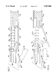
- FIG. 5 is a detailed cross-sectional view of the thrust reverser system according to the present invention in an inoperative mode
- FIG. 6 is a detailed cross-sectional view of the thrust reverser system according to the present invention in the operating mode
- FIG. 7 is a detailed cross-sectional view of a thrust reverser system according to an embodiment of the present invention.
- FIG. 8 is a detailed cross-sectional view of the thrust reverser system as shown in FIG. 7 with the thrust reverser system in the operating mode.
- a gas turbine engine 10 is typically attached to a wing 12 of an aircraft 14.
- the gas turbine engine 10 includes an outer nacelle 16 having an inlet 18 and an outlet 20.
- a fan 22 is disposed in the inlet 18 and is rotatably connected to a compressor 24 via a shaft 25.
- Compressor 24 is also connected to a turbine 26.
- a combuster chamber 28 is disposed between compressor 24 and turbine 26.
- the compressor 24, turbine 26, and combuster chamber 28 are all disposed within a core cowl 30.
- a fan air bypass duct 32 is disposed between core cowl 30 and outer nacelle 16.
- the thrust reverser system includes a structure defining a plurality of ports or passageways 40 disposed through the outer nacelle 16.
- a plurality of reverser turning vanes 42 are disposed in the ports 40.
- An internal reverser door 44 is disposed on the internal side of the vanes 42.
- An internal reverser door 44 is pivotally attached to the outer nacelle 16 by pivot a pin 46.
- An external reverser door 48 is disposed on the exterior side of the vanes the 42. The external reverser door 48 is pivotally attached to the outer nacelle 16 by a pivot pin 50.
- a plurality of rotating mixer lobes 54 are disposed at a rear portion of the core cowl 30 in a location forward of the ports 40.
- the rotating mixer lobes 54 are rotatable from a first position (as shown in FIGS. 3 and 5) for mixing air from the fan air bypass duct 32 into a core steam airflow.
- the mixer lobes 54 are rotatable to a second position (as shown in FIGS. 4 and 6) corresponding with an open position of the internal reverser door 44, for directing air from the fan air bypass duct 32 through the reverser ports 40 for generating a reverse thrust.
- the mixer lobes 54 are attached to a dual-purpose actuator 60 via an actuator arm 62 and a connector pin 64.
- a first link arm 66 is connected to the rotating mixer lobes 54 by a connector pin 68, while a second end of the first link arm 66 is connected to an intermediate portion of the external reverser door 48 by a connector pin 70.
- a second link arm 72 is provided having a first end attached to the external reverser door 48 by a pivot pin 74. A second end of the second link arm 72 is attached to the internal reverser door 44 by a connector pin 76.
- the linkage assembly is provided such that rotation of the mixer lobes 54 caused by the dual-purpose actuator 60 causes a corresponding movement of the internal and external reverser doors 44, 48. Accordingly, when the internal and external reverser doors 44, 48 are pivoted to an open position as shown in FIGS.
- the rotating mixer lobes 54 are also pivoted in order to direct a portion of the cooler fan airflow from the bypass duct 32 through the ports 40. Accordingly, the system utilizes the variable-geometry mixer lobe actuators to drive the thrust reverser system, thereby eliminating nozzle complexity and reducing system weight.
- a mixer lobe actuator 80 can be utilized for rotating the mixer lobes 54.
- the mixer lobe actuator 80 includes an actuator arm 82 which is attached to the rotating mixer lobes 54 by a connector pin 84.
- a separate reverser system actuator 86 is provided with an actuator arm 88 which is connected to a link arm 90 by a connector pin 92.
- the link arm 90 is attached via a connector pin 93 to an internal reverser door 94 which is pivotally attached to the outer nacelle 16 by a pivot pin 96.
- the reverser ports 40 can be disposed radially around the outer nacelle.
- FIG. 2 shows the preferred radial locations available for use as reverser ports.
- the fixed mixer lobes may be used as the reverser chutes, effectively doubling the amount of reverser thrust available.
- side strakes (not shown), which prevent the fan airflow from escaping into the main nozzle airstream, may be installed.
- Overall reversing efficiency may also be increased by reducing the nozzle throat area. This is accomplished by moving the convergent flaps 102 and the divergent flaps 103 toward the nozzle centerline as shown in FIG. 4. The thrust produced by the remaining engine airflow passing through the nozzle would be greatly reduced by increasing the nozzle exit area to its maximum value.
Landscapes
- Engineering & Computer Science (AREA)
- Chemical & Material Sciences (AREA)
- Combustion & Propulsion (AREA)
- Mechanical Engineering (AREA)
- General Engineering & Computer Science (AREA)
- Control Of Turbines (AREA)
Abstract
A thrust reverser system for a gas turbine engine 10 of the type which includes an outer nacelle 16 spaced apart from a core engine to define an annular bypass duct 32 therebetween and having a fan 22 disposed in an inlet for providing forced air to the bypass duct 32 and core engine. The thrust reverser system includes at least one passageway 40 through the nacelle 16 having a plurality of vanes 42 disposed therein. An internal reverser door 44 is disposed to be movable between a closed position wherein the internal reverser door 44 generally covers the at least one passageway 40 and an open position so as to allow at least a portion of air flow in the bypass duct 32 to pass through the at least one passageway 40. At least one mixer lobe 54 is disposed upstream of the at least one passageway 40. The at least one mixer lobe 54 is rotatable from a first position for mixing air from the bypass duct 32 into a core stream airflow and a second position corresponding with the open position of the internal reverser door 44 for directing air from the bypass duct 32 through the at least one passageway 40 for generating a reverser thrust.
Description
1. Technical Field
The present invention relates to gas turbine engines, commonly called jet engines, and more particularly to a thrust reverser system for use with a gas turbine engine.
2. Background Art
One reverser systems are generally known in the art for assisting in braking an aircraft during landing or in the event of an aborted takeoff attempt. Typical thrust reverser systems redirect a portion of the gases passing through the gas turbine engine in a forward direction, producing a force which acts on the aircraft opposing the direction of motion of the aircraft.
One thrust reverser purpose is to help an airplane decelerate on a runway which has been contaminated by ice, snow, or water. The incorporation of a traditional thrust reversing system on an engine designed to cruise at supersonic speeds can negatively impact the overall efficiency of the aircraft.
Currently, two common methods are utilized to provide reverse thrust in an airplane having a gas turbine engine, the "bucket" reverser and the "convergent blocker" reverser. Exemplary reverser bucket or blocker-type reverser systems are disclosed in U.S. Pat. Nos. 3,759,467 issued to Roudill; 3,837,411 issued to Nash; 3,943,707 issued to Nash; 4,373,328 issued Jones; 4,183,478 issued Rudolph; 4,185,798 issued to Dickinson; 4,353,516 issued to Soligny et al; and 5,507,143 issued to Luttgeharm. Exemplary "convergent blocker" reverser systems are disclosed in U.S. Pat. Nos. 3,262,270 issued Beavers; 3,603,090 issued to Billinger et al; 4,030,291 issued to Sargisson; 4,145,877 issued to Montgomery; 4,147,28 issued to Rodgers; 4,998,028 issued to Mutch; 5,228,641 issued to Remlaoui; and 5,575,147 issued to Nikkanen. Both the "bucket" reverser and the "convergent blocker" reverser typically involve the reversing of air from the high-temperature core stream of the engine. This requires the reverser components to be built from heavy and/or expensive heat-resistant materials which can tolerate the extreme temperatures of this environment.
In addition to requiring high-temperature materials for the thrust reverser components, these systems typically involve incorporation of high temperature materials in adjacent plane structures. These systems generally also include structure to help prevent the hot gases which leave the reverser from being undesirably reingested by the engine.
Convergent blocker type reversers often include convergent flaps to rotate to completely block the airflow and prevent it from escaping through the rear of the nozzle. This increases both the nozzle actuators stroke length and the total hydraulic power required to operate the nozzle.
Furthermore, the previously mentioned reverser systems are not easily integrated into a supersonic, variable-area nozzle. The length and complexity of the nozzle must be increased to accommodate the reverser system. This adds weight and may increase the external nozzle boattail angles, which may cause an increased drag on the engine.
Also of possible interest are U.S. Pat. Nos. 3,736,750 issued to Britt; and 3,841,091 issued to Sargisson et al.
Accordingly, the present invention provides a thrust reverser system for a gas turbine engine which does not require the use of special heat resistant materials.
The present invention provides a thrust reverser system which can be used with a supersonic engine without sacrificing noise reduction and weight reduction parameters.
The present invention provides a thrust reverser system for use with a gas turbine engine which does not cause a stall of the fan blades when deployed.
These and other advantages are obtained by providing a thrust reverser system for a gas turbine engine of the type which includes an outer nacelle spaced apart from a core engine to define an annular bypass duct therebetween and having a fan disposed in the inlet for directing forced air to the bypass duct and core engine. The thrust reverser system includes a structure defining at least one passageway through the nacelle having a plurality of vanes disposed therein. An internal reverser door is disposed on an interior side of said at least one passageway and is movable between a closed position wherein the internal reverser door generally covers the at least one passageway and an open position so as to allow at least a portion of airflow in the bypass duct to pass through the at least one passageway. At least one mixer lobe is disposed forward of the at least one passageway and is rotatable from a first position for mixing air from the bypass duct into a core stream airflow and a second position corresponding with the open position of the internal reverser door for directing air from the bypass duct through the at least one passageway for generating a reverse thrust.
An actuator is provided for moving the at least one mixer lobe between the first and second positions. Further, a linkage assembly is connected between the actuator and the internal reverser door for moving the internal reverser door to the open position when the at least one mixing lobe is moved to the second position. The linkage assembly includes a first link attached to the at least one mixer lobe and to an external reverser door. A second link is attached to the external reverser door and the internal reverser door. The actuator causes movement of the at least one mixer lobe and a corresponding movement of the internal and external reverser doors via the linkage assembly.
Accordingly, the present invention provides a device which aids in braking an aircraft during landing or in the event of an aborted takeoff attempt. The system allows thrust reverser deployment and high levels of forward thrust without causing a stall of the engine fan blades. The system also reverses only a portion of the fan airflow, but greatly reduces the thrust of the remaining fan airflow and the core airflow through modulation of the nozzle throat and exit areas.
The system also utilizes the variable-geometry mixer lobe actuators to drive the thrust reverser system, thereby eliminating nozzle complexity and reducing system weight. The system also allows more compact packaging of nozzle components than other systems proposed for an engine of this type. The compact packaging achieved by the present invention greatly reduces aircraft drag.
Further areas of applicability of the present invention will become apparent from the detailed description provided hereinafter. It should be understood however that the detailed description and specific examples, while indicating preferred embodiments of the invention, are intended for purposes of illustration only, since various changes and modifications within the spirit and scope of the invention will become apparent to those skilled in the art from this detailed description.
The present invention will become more fully understood from the detailed description and the accompanying drawings, wherein:
FIG. 1 shows an aircraft having a jet engine and illustrating the forward and reverse thrust generated by the airplane;
FIG. 2 is a perspective view of a gas turbine engine showing the location of the reverser ports disposed in the outer nacelle of the engine which is attached to a wing;
FIG. 3 is a schematic view of the gas turbine engine with the thrust reverser system according to the present invention in an inoperative mode;
FIG. 4 is a schematic of the gas turbine engine with the thrust reverser system according to the present invention in an operational mode;
FIG. 5 is a detailed cross-sectional view of the thrust reverser system according to the present invention in an inoperative mode;
FIG. 6 is a detailed cross-sectional view of the thrust reverser system according to the present invention in the operating mode;
FIG. 7 is a detailed cross-sectional view of a thrust reverser system according to an embodiment of the present invention; and
FIG. 8 is a detailed cross-sectional view of the thrust reverser system as shown in FIG. 7 with the thrust reverser system in the operating mode.
With reference to FIGS. 1-6, an embodiment of the present invention will now be described. As shown in FIGS. 1 and 2, a gas turbine engine 10 is typically attached to a wing 12 of an aircraft 14. With reference to FIGS. 3 and 4, the gas turbine engine 10 includes an outer nacelle 16 having an inlet 18 and an outlet 20. A fan 22 is disposed in the inlet 18 and is rotatably connected to a compressor 24 via a shaft 25. Compressor 24 is also connected to a turbine 26. A combuster chamber 28 is disposed between compressor 24 and turbine 26. The compressor 24, turbine 26, and combuster chamber 28 are all disposed within a core cowl 30. A fan air bypass duct 32 is disposed between core cowl 30 and outer nacelle 16. The thrust reverser system includes a structure defining a plurality of ports or passageways 40 disposed through the outer nacelle 16. A plurality of reverser turning vanes 42 are disposed in the ports 40. An internal reverser door 44 is disposed on the internal side of the vanes 42. An internal reverser door 44 is pivotally attached to the outer nacelle 16 by pivot a pin 46. An external reverser door 48 is disposed on the exterior side of the vanes the 42. The external reverser door 48 is pivotally attached to the outer nacelle 16 by a pivot pin 50.
A plurality of rotating mixer lobes 54 are disposed at a rear portion of the core cowl 30 in a location forward of the ports 40. The rotating mixer lobes 54 are rotatable from a first position (as shown in FIGS. 3 and 5) for mixing air from the fan air bypass duct 32 into a core steam airflow. The mixer lobes 54 are rotatable to a second position (as shown in FIGS. 4 and 6) corresponding with an open position of the internal reverser door 44, for directing air from the fan air bypass duct 32 through the reverser ports 40 for generating a reverse thrust. According to one embodiment, the mixer lobes 54 are attached to a dual-purpose actuator 60 via an actuator arm 62 and a connector pin 64. A first link arm 66 is connected to the rotating mixer lobes 54 by a connector pin 68, while a second end of the first link arm 66 is connected to an intermediate portion of the external reverser door 48 by a connector pin 70. A second link arm 72 is provided having a first end attached to the external reverser door 48 by a pivot pin 74. A second end of the second link arm 72 is attached to the internal reverser door 44 by a connector pin 76. The linkage assembly is provided such that rotation of the mixer lobes 54 caused by the dual-purpose actuator 60 causes a corresponding movement of the internal and external reverser doors 44, 48. Accordingly, when the internal and external reverser doors 44, 48 are pivoted to an open position as shown in FIGS. 4 and 6, the rotating mixer lobes 54 are also pivoted in order to direct a portion of the cooler fan airflow from the bypass duct 32 through the ports 40. Accordingly, the system utilizes the variable-geometry mixer lobe actuators to drive the thrust reverser system, thereby eliminating nozzle complexity and reducing system weight.
With reference to FIGS. 7 and 8, another embodiment of the present invention will be described, wherein like reference numerals are utilized to represent common elements as discussed with reference to FIGS. 1-6. According to this embodiment, a mixer lobe actuator 80 can be utilized for rotating the mixer lobes 54. The mixer lobe actuator 80 includes an actuator arm 82 which is attached to the rotating mixer lobes 54 by a connector pin 84. A separate reverser system actuator 86 is provided with an actuator arm 88 which is connected to a link arm 90 by a connector pin 92. The link arm 90 is attached via a connector pin 93 to an internal reverser door 94 which is pivotally attached to the outer nacelle 16 by a pivot pin 96. Thus, separate actuators are utilized for pivoting the rotating mixer lobes 54 and for opening the internal reverser door 94 for the reverse thrust mode. In addition, it should also be noted that the external reverser door 100 can be designed to be translated in a rearward direction in order to open the port 40 as shown in FIG. 8.
As shown in FIG. 2 the reverser ports 40 can be disposed radially around the outer nacelle. FIG. 2 shows the preferred radial locations available for use as reverser ports. If additional reverse thrust is necessary, the fixed mixer lobes may be used as the reverser chutes, effectively doubling the amount of reverser thrust available. In order to increase the amount of air forced through the reverser port 40, side strakes (not shown), which prevent the fan airflow from escaping into the main nozzle airstream, may be installed. Overall reversing efficiency may also be increased by reducing the nozzle throat area. This is accomplished by moving the convergent flaps 102 and the divergent flaps 103 toward the nozzle centerline as shown in FIG. 4. The thrust produced by the remaining engine airflow passing through the nozzle would be greatly reduced by increasing the nozzle exit area to its maximum value.
Instead of locating a large reverser port, as is done in a subsonic transport engine installation, several small ports 40 are utilized according to the present invention around the engine perimeter. To compensate for the absence of a core cowl in the location of the ports 40, the transition doors 44; 94 mate with the rotating mixer lobes 54 as shown in FIGS. 4, 6, and 8. The flow will then pass through a set of turning vanes 42 and can be further redirected forward by an external reverser door 48 to produce a reverse thrust. The system is powered by the actuator used to position the rotating mixer lobes 54 as shown in FIGS. 5 and 6, or, alternatively, by an independent actuation system as shown in FIGS. 7 and 8. Also shown in FIGS. 7 and 8 is an alternate type of external door which translates aft instead of pivoting outward.
The invention being thus described, it will be obvious that the same may be varied in many ways. Such variations are not to be regarded as a departure from the spirit and scope of the invention, and all such modifications as would be obvious to one skilled in the art are intended to be included within the scope of the following claims.
Claims (16)
1. A thrust reverser system for a gas turbine engine of the type which includes an outer nacelle spaced apart from a core engine to define an annular bypass duct therebetween and having a fan disposed in an inlet for directing forced air to the bypass duct and core engine, said thrust reverser system comprising:
a structure defining at least one passageway through the nacelle, said at least one passageway having a plurality of vanes disposed therein;
an internal reverser door disposed on an interior side of said at least one passageway and movable between a closed position wherein said internal reverser door generally covers said at least one passageway and an open position so as to allow at least a portion of air flow in said bypass duct to pass through said at least one passageway; and
at least one mixer lobe disposed upstream of said at least one passageway, said at least one mixer lobe being rotatable from a first position for mixing air from said bypass duct into a core stream airflow and a second position corresponding with said open position of said internal reverser door for directing air from said bypass duct through said at least one passageway for generating a reverse thrust.
2. The thrust reverser system according to claim 1, further comprising an actuator for moving said at least one mixer lobe between said first and second positions.
3. The thrust reverser system according to claim 2, further comprising a linkage assembly connected between said actuator and said internal reverser door for moving said internal reverser door to said open position when said at least one mixing lobe is moved to said second position.
4. The thrust reverser system according to claim 1, further comprising an external reverser door disposed on an exterior side of said at least one passageway.
5. The thrust reverser system according to claim 3, wherein said linkage assembly includes a first link attached to said at least one mixer lobe and to said external reverser door and a second link attached to said external reverser door and said internal reverser door, wherein said actuator causes movement of said at least one mixer lobe and a corresponding movement of said internal and external reverser doors.
6. The thrust reverser system according to claim 3, further comprising a second actuator for moving said internal reverser door between said closed and open positions.
7. The thrust reverser system according to claim 1, wherein said internal reverser door is pivotally attached to said outer nacelle.
8. A gas turbine engine, comprising:
a core engine including compressor, a combustion chamber and a turbine disposed within a core cowl;
an outer nacelle spaced apart from said core cowl to defame an annular bypass duct therebetween and having a fan disposed in an inlet for directing forced air to the bypass duct and core engine;
at least one passageway through the nacelle having a plurality of vanes disposed therein;
an internal reverser door disposed to be movable between a closed position wherein said internal reverser door generally covers said at least one passageway and an open position so as to allow at least a portion of air flow in said bypass duct to pass through said at least one passageway; and
at least one mixer lobe disposed upstream of said at least one passageway, said at least one mixer lobe being rotatable from a first position for mixing air from said bypass duct into a core stream airflow and a second position corresponding with said open position of said internal reverser door for directing air from said bypass duct through said at least one passageway for generating a reverse thrust.
9. The gas turbine engine according to claim 8, further comprising an actuator for moving said at least one mixer lobe between said first and second positions.
10. The gas turbine engine according to claim 9, further comprising a linkage assembly connected between said actuator and said internal reverser door for moving said internal reverser door to said open position when said at least one mixing lobe is moved to said second position.
11. The gas turbine engine according to claim 10, further comprising an external reverser door disposed on an exterior side of said at least one passageway.
12. The gas turbine engine according to claim 11, wherein said linkage assembly includes a first link attached to said at least one mixer lobe and to said external reverser door and a second link attached to said external reverser door and said internal reverser door, wherein said actuator causes movement of said at least one mixer lobe and a corresponding movement of said internal and external reverser doors.
13. The gas turbine engine according to claim 9, further comprising a second actuator for moving said internal reverser door between said closed and open positions.
14. The gas turbine engine according to claim 8, wherein said internal reverser door is pivotally attached to said outer nacelle.
15. The gas turbine engine according to claim 8, further comprising convergent and divergent flaps within an outlet portion of said outer nacelle.
16. A method of generating a reverse thrust from an aircraft engine of the type which includes an outer nacelle spaced apart from a core engine to define an annular bypass duct therebetween and having a fan disposed in an inlet for directing forced air to the bypass duct and core engine, comprising the steps of:
providing at least one passageway through the outer nacelle;
mounting a plurality of vanes in said at least one passageway;
directing air from said annular bypass duct through said at least one passageway by pivoting at least one mixer lobe disposed upstream of said at least one passageway for directing air from said bypass duct through said at least one passageway for generating a reverse thrust.
Priority Applications (1)
| Application Number | Priority Date | Filing Date | Title |
|---|---|---|---|
| US08/889,403 US5987880A (en) | 1997-07-08 | 1997-07-08 | Supersonic engine, multi-port thrust reversing system |
Applications Claiming Priority (1)
| Application Number | Priority Date | Filing Date | Title |
|---|---|---|---|
| US08/889,403 US5987880A (en) | 1997-07-08 | 1997-07-08 | Supersonic engine, multi-port thrust reversing system |
Publications (1)
| Publication Number | Publication Date |
|---|---|
| US5987880A true US5987880A (en) | 1999-11-23 |
Family
ID=25395026
Family Applications (1)
| Application Number | Title | Priority Date | Filing Date |
|---|---|---|---|
| US08/889,403 Expired - Fee Related US5987880A (en) | 1997-07-08 | 1997-07-08 | Supersonic engine, multi-port thrust reversing system |
Country Status (1)
| Country | Link |
|---|---|
| US (1) | US5987880A (en) |
Cited By (48)
| Publication number | Priority date | Publication date | Assignee | Title |
|---|---|---|---|---|
| US6158211A (en) * | 1998-06-18 | 2000-12-12 | Hispano Suiza Aerostructures | Turbojet-engine thrust reverser with scoop-doors of adjustable exhaust cross-section |
| US6170255B1 (en) * | 1998-02-04 | 2001-01-09 | Hispano-Suiza Aerostructures | Turbojet thrust reverser with downstream obstacles |
| US6311928B1 (en) * | 2000-01-05 | 2001-11-06 | Stage Iii Technologies, L.C. | Jet engine cascade thrust reverser for use with mixer/ejector noise suppressor |
| US6427801B1 (en) * | 2000-08-10 | 2002-08-06 | John J. Dugan | Apparatus for reducing noise in the jet engine |
| US6622964B2 (en) * | 2001-04-05 | 2003-09-23 | Hurel Hispano-Le-Havre | System for the synchronized locking of the doors of a thrust reverser |
| US20040068978A1 (en) * | 2002-10-11 | 2004-04-15 | Jean-Pierre Lair | Bifold door thrust reverser |
| US20040195434A1 (en) * | 2003-03-04 | 2004-10-07 | Dean Parham | Thrust reverser utilizing integrated structural bypass duct |
| WO2004097202A3 (en) * | 2003-03-22 | 2005-01-20 | Nordam Group Inc | Toggle interlocked thrust reverser |
| US20070007388A1 (en) * | 2005-06-27 | 2007-01-11 | Harrison Geoffrey E | Thrust reversers including locking assemblies for inhibiting deflection |
| US20080010969A1 (en) * | 2006-07-11 | 2008-01-17 | Thomas Anthony Hauer | Gas turbine engine and method of operating same |
| US20080092548A1 (en) * | 2006-10-20 | 2008-04-24 | United Technologies Corporation | Gas turbine engine having slim-line nacelle |
| US20080112799A1 (en) * | 2006-11-10 | 2008-05-15 | United Technologies Corporation | Gas turbine engine providing simulated boundary layer thickness increase |
| US20080283676A1 (en) * | 2007-05-18 | 2008-11-20 | Jain Ashok K | Variable contraction ratio nacelle assembly for a gas turbine engine |
| US20080286094A1 (en) * | 2007-05-16 | 2008-11-20 | Jain Ashok K | Variable geometry nacelle assembly for a gas turbine engine |
| US20090003997A1 (en) * | 2007-06-28 | 2009-01-01 | Jain Ashok K | Variable shape inlet section for a nacelle assembly of a gas turbine engine |
| US20090008508A1 (en) * | 2007-07-02 | 2009-01-08 | Jain Ashok K | Variable contour nacelle assembly for a gas turbine engine |
| US20090014597A1 (en) * | 2006-10-12 | 2009-01-15 | Aerion Corporation | Supersonic aircraft jet engine |
| US20090121083A1 (en) * | 2007-11-13 | 2009-05-14 | Jain Ashok K | Nacelle Flow Assembly |
| US20090155067A1 (en) * | 2007-12-14 | 2009-06-18 | Martin Haas | Nacelle assembly with turbulators |
| US20090155046A1 (en) * | 2007-12-14 | 2009-06-18 | Martin Haas | Nacelle assembly having inlet bleed |
| US7600371B2 (en) | 2005-10-18 | 2009-10-13 | The Boeing Company | Thrust reversers including support members for inhibiting deflection |
| US20100072324A1 (en) * | 2008-09-02 | 2010-03-25 | Airbus Operations | Nacelle for double flow engine |
| US7690190B2 (en) | 2005-05-11 | 2010-04-06 | The Boeing Company | Aircraft systems including cascade thrust reversers |
| US20110101158A1 (en) * | 2005-03-29 | 2011-05-05 | The Boeing Company | Thrust Reversers Including Monolithic Components |
| WO2011135216A1 (en) * | 2010-04-28 | 2011-11-03 | Aircelle | Reverser having doors |
| US20120036716A1 (en) * | 2010-08-13 | 2012-02-16 | Spirit Aerosystems, Inc. | Aerodynamic device for thrust reverser cascades |
| US8127532B2 (en) | 2008-11-26 | 2012-03-06 | The Boeing Company | Pivoting fan nozzle nacelle |
| CN102834623A (en) * | 2010-04-10 | 2012-12-19 | 艾法斯公司 | Peripheral control ejector |
| US8408491B2 (en) | 2007-04-24 | 2013-04-02 | United Technologies Corporation | Nacelle assembly having inlet airfoil for a gas turbine engine |
| CN103732900A (en) * | 2011-08-08 | 2014-04-16 | 埃尔塞乐公司 | Thrust reverser device |
| US8720818B1 (en) * | 2008-09-02 | 2014-05-13 | Airbus Operations Sas | Thrust reverser and nacelle for aircraft equipped with at least one such reverser |
| US8959889B2 (en) | 2008-11-26 | 2015-02-24 | The Boeing Company | Method of varying a fan duct nozzle throat area of a gas turbine engine |
| US20150113945A1 (en) * | 2013-10-24 | 2015-04-30 | United Technologies Corporation | Pivoting Blocker Door |
| US9181898B2 (en) * | 2011-09-20 | 2015-11-10 | United Technologies Corporation | Thrust reverser for a gas turbine engine with moveable doors |
| US20160160799A1 (en) * | 2014-11-06 | 2016-06-09 | Rohr, Inc. | Split sleeve hidden door thrust reverser |
| US20160201601A1 (en) * | 2015-01-14 | 2016-07-14 | The Boeing Company | Methods and apparatus to vary reverse thrust of aircraft engines |
| US20160273488A1 (en) * | 2015-03-19 | 2016-09-22 | Rohr, Inc. | Cascade vane leading edge |
| US20160363097A1 (en) * | 2015-06-09 | 2016-12-15 | The Boeing Company | Thrust Reverser Apparatus and Method |
| US9784214B2 (en) * | 2014-11-06 | 2017-10-10 | Rohr, Inc. | Thrust reverser with hidden linkage blocker doors |
| US9863368B1 (en) * | 2016-09-09 | 2018-01-09 | Florida Turbine Technologies, Inc. | Aircraft with gas turbine engine having outer bypass elements removed |
| US9874176B2 (en) | 2015-01-14 | 2018-01-23 | The Boeing Company | Methods and apparatus to vary reverse thrust of aircraft engines |
| US9976696B2 (en) | 2016-06-21 | 2018-05-22 | Rohr, Inc. | Linear actuator with multi-degree of freedom mounting structure |
| US10006404B2 (en) | 2012-02-28 | 2018-06-26 | United Technologies Corporation | Gas turbine engine thrust reverser system |
| CN109625251A (en) * | 2017-10-09 | 2019-04-16 | 空中客车运作有限责任公司 | For flowing the vertical tail units of control |
| US10655564B2 (en) | 2016-05-13 | 2020-05-19 | Rohr, Inc. | Thrust reverser system with hidden blocker doors |
| US10967955B2 (en) * | 2017-10-09 | 2021-04-06 | Airbus Operations Gmbh | Vertical tail unit for flow control |
| US11255295B2 (en) * | 2016-10-18 | 2022-02-22 | Safran Aircraft Engines | Propulsion assembly comprising a duct for feeding the gas generator in an inter-duct casing |
| US11891026B1 (en) * | 2023-05-16 | 2024-02-06 | King Faisal University | Reverse thrust braking system |
Citations (28)
| Publication number | Priority date | Publication date | Assignee | Title |
|---|---|---|---|---|
| US3248878A (en) * | 1963-09-18 | 1966-05-03 | Gen Electric | Thrust deflector and reverser |
| US3262270A (en) * | 1965-06-07 | 1966-07-26 | Gen Electric | Thrust reverser |
| US3601992A (en) * | 1970-06-10 | 1971-08-31 | Rohr Corp | Thrust reversing apparatus |
| US3603090A (en) * | 1968-08-08 | 1971-09-07 | Rolls Royce | Thrust reverser for fan type jet propulsion engines |
| US3736750A (en) * | 1971-03-12 | 1973-06-05 | Rolls Royce | Power plant |
| US3739582A (en) * | 1972-04-13 | 1973-06-19 | Rohr Industries Inc | Thrust reversing apparatus |
| US3759467A (en) * | 1969-07-10 | 1973-09-18 | Etude Construction De Monteurs | Method and means for opposing the rotation of a windmilling turbojet rotor during flight |
| US3764096A (en) * | 1972-02-24 | 1973-10-09 | Rohr Industries Inc | Thrust reversing apparatus |
| US3831376A (en) * | 1973-02-05 | 1974-08-27 | Boeing Co | Thrust reverser |
| US3837411A (en) * | 1973-11-21 | 1974-09-24 | Gen Electric | Diverter valve for a gas turbine with an augmenter |
| US3841091A (en) * | 1973-05-21 | 1974-10-15 | Gen Electric | Multi-mission tandem propulsion system |
| US3943707A (en) * | 1974-10-23 | 1976-03-16 | General Electric Company | Gas turbine engine exhaust nozzle diverter valve |
| US4030291A (en) * | 1976-01-02 | 1977-06-21 | General Electric Company | Thrust reverser for a gas turbofan engine |
| FR2337258A1 (en) * | 1976-01-03 | 1977-07-29 | Plessey Handel Investment Ag | Jet engine thrust reverser - has shutters connected to operating cylinders by scissors linkages |
| US4145877A (en) * | 1976-07-13 | 1979-03-27 | Short Brothers & Harland Limited | Actuating mechanism for the thrust reversal doors of a gas turbine engine |
| US4147028A (en) * | 1976-09-11 | 1979-04-03 | Rolls-Royce Limited | Jet engine thrust reverser and cowl structure |
| US4183478A (en) * | 1977-11-25 | 1980-01-15 | The Boeing Company | Jet thrust reverser |
| US4184798A (en) * | 1978-01-23 | 1980-01-22 | Park-Ohio Industries, Inc. | Workpiece rotating and feeding apparatus |
| US4353516A (en) * | 1979-07-24 | 1982-10-12 | Societe Nationale D'etude Et De Construction De Moteurs D'aviation, "S.N.E.C.M.A." | Thrust reverser and silencer assembly of turbojet engines |
| US4373328A (en) * | 1980-10-22 | 1983-02-15 | United Technologies Corporation | Thrust reverser |
| US4805401A (en) * | 1987-08-18 | 1989-02-21 | United Technologies Corporation | Control vent for diverting exhaust nozzle |
| US4998409A (en) * | 1989-09-25 | 1991-03-12 | Rohr Industries, Inc. | Thrust reverser torque ring |
| US5228641A (en) * | 1991-08-15 | 1993-07-20 | Rohr, Inc. | Cascade type aircraft engine thrust reverser with hidden link actuator |
| US5347808A (en) * | 1991-06-24 | 1994-09-20 | Societe De Construction Des Avions Hurel-Dubois | Jet-engine thrust reversers |
| US5507143A (en) * | 1993-04-13 | 1996-04-16 | The Boeing Company | Cascade assembly for use in a thrust-reversing mechanism |
| US5575147A (en) * | 1994-12-22 | 1996-11-19 | United Technologies Corporation | Compact thrust reverser |
| US5598701A (en) * | 1994-02-01 | 1997-02-04 | Rolls-Royce Plc | Frangible connection for a thrust reverser for a ducted fan gas turbine |
| US5666802A (en) * | 1993-02-08 | 1997-09-16 | Lair; Jean-Pierre | Turbine engine equipped with thrust reverser |
-
1997
- 1997-07-08 US US08/889,403 patent/US5987880A/en not_active Expired - Fee Related
Patent Citations (28)
| Publication number | Priority date | Publication date | Assignee | Title |
|---|---|---|---|---|
| US3248878A (en) * | 1963-09-18 | 1966-05-03 | Gen Electric | Thrust deflector and reverser |
| US3262270A (en) * | 1965-06-07 | 1966-07-26 | Gen Electric | Thrust reverser |
| US3603090A (en) * | 1968-08-08 | 1971-09-07 | Rolls Royce | Thrust reverser for fan type jet propulsion engines |
| US3759467A (en) * | 1969-07-10 | 1973-09-18 | Etude Construction De Monteurs | Method and means for opposing the rotation of a windmilling turbojet rotor during flight |
| US3601992A (en) * | 1970-06-10 | 1971-08-31 | Rohr Corp | Thrust reversing apparatus |
| US3736750A (en) * | 1971-03-12 | 1973-06-05 | Rolls Royce | Power plant |
| US3764096A (en) * | 1972-02-24 | 1973-10-09 | Rohr Industries Inc | Thrust reversing apparatus |
| US3739582A (en) * | 1972-04-13 | 1973-06-19 | Rohr Industries Inc | Thrust reversing apparatus |
| US3831376A (en) * | 1973-02-05 | 1974-08-27 | Boeing Co | Thrust reverser |
| US3841091A (en) * | 1973-05-21 | 1974-10-15 | Gen Electric | Multi-mission tandem propulsion system |
| US3837411A (en) * | 1973-11-21 | 1974-09-24 | Gen Electric | Diverter valve for a gas turbine with an augmenter |
| US3943707A (en) * | 1974-10-23 | 1976-03-16 | General Electric Company | Gas turbine engine exhaust nozzle diverter valve |
| US4030291A (en) * | 1976-01-02 | 1977-06-21 | General Electric Company | Thrust reverser for a gas turbofan engine |
| FR2337258A1 (en) * | 1976-01-03 | 1977-07-29 | Plessey Handel Investment Ag | Jet engine thrust reverser - has shutters connected to operating cylinders by scissors linkages |
| US4145877A (en) * | 1976-07-13 | 1979-03-27 | Short Brothers & Harland Limited | Actuating mechanism for the thrust reversal doors of a gas turbine engine |
| US4147028A (en) * | 1976-09-11 | 1979-04-03 | Rolls-Royce Limited | Jet engine thrust reverser and cowl structure |
| US4183478A (en) * | 1977-11-25 | 1980-01-15 | The Boeing Company | Jet thrust reverser |
| US4184798A (en) * | 1978-01-23 | 1980-01-22 | Park-Ohio Industries, Inc. | Workpiece rotating and feeding apparatus |
| US4353516A (en) * | 1979-07-24 | 1982-10-12 | Societe Nationale D'etude Et De Construction De Moteurs D'aviation, "S.N.E.C.M.A." | Thrust reverser and silencer assembly of turbojet engines |
| US4373328A (en) * | 1980-10-22 | 1983-02-15 | United Technologies Corporation | Thrust reverser |
| US4805401A (en) * | 1987-08-18 | 1989-02-21 | United Technologies Corporation | Control vent for diverting exhaust nozzle |
| US4998409A (en) * | 1989-09-25 | 1991-03-12 | Rohr Industries, Inc. | Thrust reverser torque ring |
| US5347808A (en) * | 1991-06-24 | 1994-09-20 | Societe De Construction Des Avions Hurel-Dubois | Jet-engine thrust reversers |
| US5228641A (en) * | 1991-08-15 | 1993-07-20 | Rohr, Inc. | Cascade type aircraft engine thrust reverser with hidden link actuator |
| US5666802A (en) * | 1993-02-08 | 1997-09-16 | Lair; Jean-Pierre | Turbine engine equipped with thrust reverser |
| US5507143A (en) * | 1993-04-13 | 1996-04-16 | The Boeing Company | Cascade assembly for use in a thrust-reversing mechanism |
| US5598701A (en) * | 1994-02-01 | 1997-02-04 | Rolls-Royce Plc | Frangible connection for a thrust reverser for a ducted fan gas turbine |
| US5575147A (en) * | 1994-12-22 | 1996-11-19 | United Technologies Corporation | Compact thrust reverser |
Cited By (90)
| Publication number | Priority date | Publication date | Assignee | Title |
|---|---|---|---|---|
| US6170255B1 (en) * | 1998-02-04 | 2001-01-09 | Hispano-Suiza Aerostructures | Turbojet thrust reverser with downstream obstacles |
| US6158211A (en) * | 1998-06-18 | 2000-12-12 | Hispano Suiza Aerostructures | Turbojet-engine thrust reverser with scoop-doors of adjustable exhaust cross-section |
| US6311928B1 (en) * | 2000-01-05 | 2001-11-06 | Stage Iii Technologies, L.C. | Jet engine cascade thrust reverser for use with mixer/ejector noise suppressor |
| US6427801B1 (en) * | 2000-08-10 | 2002-08-06 | John J. Dugan | Apparatus for reducing noise in the jet engine |
| US6622964B2 (en) * | 2001-04-05 | 2003-09-23 | Hurel Hispano-Le-Havre | System for the synchronized locking of the doors of a thrust reverser |
| WO2004046533A2 (en) * | 2002-10-11 | 2004-06-03 | The Nordam Group, Inc. | Bifold door thrust reverser |
| US20040068978A1 (en) * | 2002-10-11 | 2004-04-15 | Jean-Pierre Lair | Bifold door thrust reverser |
| WO2004046533A3 (en) * | 2002-10-11 | 2004-08-12 | Nordam Group Inc | Bifold door thrust reverser |
| US6895742B2 (en) * | 2002-10-11 | 2005-05-24 | The Nordam Group, Inc. | Bifold door thrust reverser |
| US20040195434A1 (en) * | 2003-03-04 | 2004-10-07 | Dean Parham | Thrust reverser utilizing integrated structural bypass duct |
| US7124981B2 (en) * | 2003-03-04 | 2006-10-24 | The Boeing Company | Thrust reverser utilizing integrated structural bypass duct |
| WO2004097202A3 (en) * | 2003-03-22 | 2005-01-20 | Nordam Group Inc | Toggle interlocked thrust reverser |
| US20050039438A1 (en) * | 2003-03-22 | 2005-02-24 | Jean-Pierre Lair | Toggle interlocked thrust reverser |
| US6976352B2 (en) * | 2003-03-22 | 2005-12-20 | The Nordam Group, Inc. | Toggle interlocked thrust reverser |
| US20110101158A1 (en) * | 2005-03-29 | 2011-05-05 | The Boeing Company | Thrust Reversers Including Monolithic Components |
| US7690190B2 (en) | 2005-05-11 | 2010-04-06 | The Boeing Company | Aircraft systems including cascade thrust reversers |
| US20070007388A1 (en) * | 2005-06-27 | 2007-01-11 | Harrison Geoffrey E | Thrust reversers including locking assemblies for inhibiting deflection |
| US7559507B2 (en) * | 2005-06-27 | 2009-07-14 | The Boeing Company | Thrust reversers including locking assemblies for inhibiting deflection |
| US7600371B2 (en) | 2005-10-18 | 2009-10-13 | The Boeing Company | Thrust reversers including support members for inhibiting deflection |
| US20080010969A1 (en) * | 2006-07-11 | 2008-01-17 | Thomas Anthony Hauer | Gas turbine engine and method of operating same |
| US20090014597A1 (en) * | 2006-10-12 | 2009-01-15 | Aerion Corporation | Supersonic aircraft jet engine |
| EP2084061A4 (en) * | 2006-10-12 | 2013-07-24 | Aerion Corp | Supersonic aircraft jet engine |
| US7837142B2 (en) * | 2006-10-12 | 2010-11-23 | Aerion Corporation | Supersonic aircraft jet engine |
| EP2084061A2 (en) * | 2006-10-12 | 2009-08-05 | Aerion Corporation | Supersonic aircraft jet engine |
| US8353164B2 (en) | 2006-10-20 | 2013-01-15 | United Technologies Corporation | Gas turbine engine having slim-line nacelle |
| US8726632B2 (en) | 2006-10-20 | 2014-05-20 | United Technologies Corporation | Gas turbine engine having slim-line nacelle |
| US8844294B2 (en) | 2006-10-20 | 2014-09-30 | United Technologies Corporation | Gas turbine engine having slim-line nacelle |
| US7797944B2 (en) | 2006-10-20 | 2010-09-21 | United Technologies Corporation | Gas turbine engine having slim-line nacelle |
| US20100269512A1 (en) * | 2006-10-20 | 2010-10-28 | Morford Stephen A | Gas turbine engine having slim-line nacelle |
| US20100269486A1 (en) * | 2006-10-20 | 2010-10-28 | Morford Stephen A | Gas turbine engine having slim-line nacelle |
| US20080092548A1 (en) * | 2006-10-20 | 2008-04-24 | United Technologies Corporation | Gas turbine engine having slim-line nacelle |
| US8209953B2 (en) | 2006-11-10 | 2012-07-03 | United Technologies Corporation | Gas turbine engine system providing simulated boundary layer thickness increase |
| US20080112799A1 (en) * | 2006-11-10 | 2008-05-15 | United Technologies Corporation | Gas turbine engine providing simulated boundary layer thickness increase |
| US20110072828A1 (en) * | 2006-11-10 | 2011-03-31 | Michael Winter | Gas turbine engine system providing simulated boundary layer thickness increase |
| US7870721B2 (en) | 2006-11-10 | 2011-01-18 | United Technologies Corporation | Gas turbine engine providing simulated boundary layer thickness increase |
| US8408491B2 (en) | 2007-04-24 | 2013-04-02 | United Technologies Corporation | Nacelle assembly having inlet airfoil for a gas turbine engine |
| US20080286094A1 (en) * | 2007-05-16 | 2008-11-20 | Jain Ashok K | Variable geometry nacelle assembly for a gas turbine engine |
| US8205430B2 (en) | 2007-05-16 | 2012-06-26 | United Technologies Corporation | Variable geometry nacelle assembly for a gas turbine engine |
| US20080283676A1 (en) * | 2007-05-18 | 2008-11-20 | Jain Ashok K | Variable contraction ratio nacelle assembly for a gas turbine engine |
| US8727267B2 (en) | 2007-05-18 | 2014-05-20 | United Technologies Corporation | Variable contraction ratio nacelle assembly for a gas turbine engine |
| US8402739B2 (en) | 2007-06-28 | 2013-03-26 | United Technologies Corporation | Variable shape inlet section for a nacelle assembly of a gas turbine engine |
| US20090003997A1 (en) * | 2007-06-28 | 2009-01-01 | Jain Ashok K | Variable shape inlet section for a nacelle assembly of a gas turbine engine |
| US9228534B2 (en) | 2007-07-02 | 2016-01-05 | United Technologies Corporation | Variable contour nacelle assembly for a gas turbine engine |
| US20090008508A1 (en) * | 2007-07-02 | 2009-01-08 | Jain Ashok K | Variable contour nacelle assembly for a gas turbine engine |
| US8596573B2 (en) | 2007-11-13 | 2013-12-03 | United Technologies Corporation | Nacelle flow assembly |
| US20110020105A1 (en) * | 2007-11-13 | 2011-01-27 | Jain Ashok K | Nacelle flow assembly |
| US9004399B2 (en) | 2007-11-13 | 2015-04-14 | United Technologies Corporation | Nacelle flow assembly |
| US20090121083A1 (en) * | 2007-11-13 | 2009-05-14 | Jain Ashok K | Nacelle Flow Assembly |
| US8282037B2 (en) | 2007-11-13 | 2012-10-09 | United Technologies Corporation | Nacelle flow assembly |
| US8192147B2 (en) | 2007-12-14 | 2012-06-05 | United Technologies Corporation | Nacelle assembly having inlet bleed |
| US20090155067A1 (en) * | 2007-12-14 | 2009-06-18 | Martin Haas | Nacelle assembly with turbulators |
| US8186942B2 (en) | 2007-12-14 | 2012-05-29 | United Technologies Corporation | Nacelle assembly with turbulators |
| US20090155046A1 (en) * | 2007-12-14 | 2009-06-18 | Martin Haas | Nacelle assembly having inlet bleed |
| US8162257B2 (en) * | 2008-02-09 | 2012-04-24 | Airbus Operations Sas | Nacelle for double flow engine |
| US8720818B1 (en) * | 2008-09-02 | 2014-05-13 | Airbus Operations Sas | Thrust reverser and nacelle for aircraft equipped with at least one such reverser |
| US20100072324A1 (en) * | 2008-09-02 | 2010-03-25 | Airbus Operations | Nacelle for double flow engine |
| US8127532B2 (en) | 2008-11-26 | 2012-03-06 | The Boeing Company | Pivoting fan nozzle nacelle |
| US8959889B2 (en) | 2008-11-26 | 2015-02-24 | The Boeing Company | Method of varying a fan duct nozzle throat area of a gas turbine engine |
| CN102834623A (en) * | 2010-04-10 | 2012-12-19 | 艾法斯公司 | Peripheral control ejector |
| WO2011135216A1 (en) * | 2010-04-28 | 2011-11-03 | Aircelle | Reverser having doors |
| US8783010B2 (en) | 2010-04-28 | 2014-07-22 | Aircelle | Cascade type thrust reverser having a pivoting door |
| FR2959531A1 (en) * | 2010-04-28 | 2011-11-04 | Aircelle Sa | DOOR INVERTER |
| US20120036716A1 (en) * | 2010-08-13 | 2012-02-16 | Spirit Aerosystems, Inc. | Aerodynamic device for thrust reverser cascades |
| US8484944B2 (en) * | 2010-08-13 | 2013-07-16 | Spirit Aerosystems, Inc. | Aerodynamic device for thrust reverser cascades |
| CN103732900A (en) * | 2011-08-08 | 2014-04-16 | 埃尔塞乐公司 | Thrust reverser device |
| US9181898B2 (en) * | 2011-09-20 | 2015-11-10 | United Technologies Corporation | Thrust reverser for a gas turbine engine with moveable doors |
| US10006404B2 (en) | 2012-02-28 | 2018-06-26 | United Technologies Corporation | Gas turbine engine thrust reverser system |
| US20150113945A1 (en) * | 2013-10-24 | 2015-04-30 | United Technologies Corporation | Pivoting Blocker Door |
| US10156206B2 (en) * | 2013-10-24 | 2018-12-18 | United Technologies Corporation | Pivoting blocker door |
| US20160160799A1 (en) * | 2014-11-06 | 2016-06-09 | Rohr, Inc. | Split sleeve hidden door thrust reverser |
| US11434850B2 (en) | 2014-11-06 | 2022-09-06 | Rohr, Inc. | Split sleeve hidden door thrust reverser |
| US9784214B2 (en) * | 2014-11-06 | 2017-10-10 | Rohr, Inc. | Thrust reverser with hidden linkage blocker doors |
| US10309343B2 (en) * | 2014-11-06 | 2019-06-04 | Rohr, Inc. | Split sleeve hidden door thrust reverser |
| US20160201601A1 (en) * | 2015-01-14 | 2016-07-14 | The Boeing Company | Methods and apparatus to vary reverse thrust of aircraft engines |
| US10018151B2 (en) * | 2015-01-14 | 2018-07-10 | The Boeing Company | Methods and apparatus to vary reverse thrust of aircraft engines |
| US9874176B2 (en) | 2015-01-14 | 2018-01-23 | The Boeing Company | Methods and apparatus to vary reverse thrust of aircraft engines |
| US20160273488A1 (en) * | 2015-03-19 | 2016-09-22 | Rohr, Inc. | Cascade vane leading edge |
| US20160363097A1 (en) * | 2015-06-09 | 2016-12-15 | The Boeing Company | Thrust Reverser Apparatus and Method |
| US10041443B2 (en) * | 2015-06-09 | 2018-08-07 | The Boeing Company | Thrust reverser apparatus and method |
| EP3103995A3 (en) * | 2015-06-09 | 2017-02-22 | The Boeing Company | Thrust reverser apparatus and method |
| US10655564B2 (en) | 2016-05-13 | 2020-05-19 | Rohr, Inc. | Thrust reverser system with hidden blocker doors |
| US9976696B2 (en) | 2016-06-21 | 2018-05-22 | Rohr, Inc. | Linear actuator with multi-degree of freedom mounting structure |
| US9863368B1 (en) * | 2016-09-09 | 2018-01-09 | Florida Turbine Technologies, Inc. | Aircraft with gas turbine engine having outer bypass elements removed |
| US11255295B2 (en) * | 2016-10-18 | 2022-02-22 | Safran Aircraft Engines | Propulsion assembly comprising a duct for feeding the gas generator in an inter-duct casing |
| CN109625251A (en) * | 2017-10-09 | 2019-04-16 | 空中客车运作有限责任公司 | For flowing the vertical tail units of control |
| US10967955B2 (en) * | 2017-10-09 | 2021-04-06 | Airbus Operations Gmbh | Vertical tail unit for flow control |
| US10974817B2 (en) * | 2017-10-09 | 2021-04-13 | Airbus Operations Gmbh | Vertical tail unit for flow control |
| US20210214072A1 (en) * | 2017-10-09 | 2021-07-15 | Airbus Operations Gmbh | Vertical tail unit for flow control |
| US11565795B2 (en) * | 2017-10-09 | 2023-01-31 | Airbus Operations Gmbh | Vertical tail unit for flow control |
| US11891026B1 (en) * | 2023-05-16 | 2024-02-06 | King Faisal University | Reverse thrust braking system |
Similar Documents
| Publication | Publication Date | Title |
|---|---|---|
| US5987880A (en) | Supersonic engine, multi-port thrust reversing system | |
| US11499502B2 (en) | Dual function cascade integrated variable area fan nozzle and thrust reverser | |
| US6968675B2 (en) | Cascadeless fan thrust reverser with plume control | |
| EP1430212B1 (en) | Converging nozzle thrust reverser | |
| US5315821A (en) | Aircraft bypass turbofan engine thrust reverser | |
| US8127532B2 (en) | Pivoting fan nozzle nacelle | |
| US8844294B2 (en) | Gas turbine engine having slim-line nacelle | |
| US8104261B2 (en) | Tri-body variable area fan nozzle and thrust reverser | |
| US5402638A (en) | Spillage drag reducing flade engine | |
| US4147027A (en) | Thrust reverser nozzle | |
| US8418436B2 (en) | Variable area fan nozzle and thrust reverser | |
| EP1470328B1 (en) | Turbofan exhaust nozzle and method of reducing noise in such a nozzle | |
| EP0913569B1 (en) | Gas turbine housing structure | |
| US8959889B2 (en) | Method of varying a fan duct nozzle throat area of a gas turbine engine | |
| US5794434A (en) | Aircraft thrust reverser system with linearly translating inner and outer doors | |
| GB1561139A (en) | Gas turbine engine exhaust including a pressure balanced flap | |
| JPH0713480B2 (en) | How to drive an aircraft bypass turbofan engine | |
| JPS633136B2 (en) | ||
| JPS6157461B2 (en) | ||
| US5203164A (en) | Method and apparatus for quieting a turbojet engine | |
| US5852928A (en) | Thrust reverser with extendible pivoting baffle | |
| US8720182B2 (en) | Integrated variable area nozzle and thrust reversing mechanism | |
| RU2415287C2 (en) | Double-stage turbofan engine | |
| US5255510A (en) | Thrust reverser for a high-bypass ratio turbofan engine | |
| US4463903A (en) | Turbomachine ejector nozzle |
Legal Events
| Date | Code | Title | Description |
|---|---|---|---|
| AS | Assignment |
Owner name: MCDONNELL DOUGLAS CORPORATION, CALIFORNIA Free format text: ASSIGNMENT OF ASSIGNORS INTEREST;ASSIGNOR:CULBERTSON, CHRISTOPHER C.;REEL/FRAME:008667/0603 Effective date: 19970707 |
|
| CC | Certificate of correction | ||
| FEPP | Fee payment procedure |
Free format text: PAYOR NUMBER ASSIGNED (ORIGINAL EVENT CODE: ASPN); ENTITY STATUS OF PATENT OWNER: LARGE ENTITY |
|
| FPAY | Fee payment |
Year of fee payment: 4 |
|
| REMI | Maintenance fee reminder mailed | ||
| LAPS | Lapse for failure to pay maintenance fees | ||
| STCH | Information on status: patent discontinuation |
Free format text: PATENT EXPIRED DUE TO NONPAYMENT OF MAINTENANCE FEES UNDER 37 CFR 1.362 |
|
| FP | Lapsed due to failure to pay maintenance fee |
Effective date: 20071123 |