US5966987A - Controlling device of tunable filter - Google Patents
Controlling device of tunable filter Download PDFInfo
- Publication number
- US5966987A US5966987A US09/047,383 US4738398A US5966987A US 5966987 A US5966987 A US 5966987A US 4738398 A US4738398 A US 4738398A US 5966987 A US5966987 A US 5966987A
- Authority
- US
- United States
- Prior art keywords
- movable member
- tunable filter
- worm gear
- base
- holder
- Prior art date
- Legal status (The legal status is an assumption and is not a legal conclusion. Google has not performed a legal analysis and makes no representation as to the accuracy of the status listed.)
- Expired - Fee Related
Links
Images


Classifications
-
- G—PHYSICS
- G02—OPTICS
- G02B—OPTICAL ELEMENTS, SYSTEMS OR APPARATUS
- G02B6/00—Light guides; Structural details of arrangements comprising light guides and other optical elements, e.g. couplings
- G02B6/24—Coupling light guides
- G02B6/26—Optical coupling means
- G02B6/28—Optical coupling means having data bus means, i.e. plural waveguides interconnected and providing an inherently bidirectional system by mixing and splitting signals
- G02B6/293—Optical coupling means having data bus means, i.e. plural waveguides interconnected and providing an inherently bidirectional system by mixing and splitting signals with wavelength selective means
- G02B6/29346—Optical coupling means having data bus means, i.e. plural waveguides interconnected and providing an inherently bidirectional system by mixing and splitting signals with wavelength selective means operating by wave or beam interference
- G02B6/29361—Interference filters, e.g. multilayer coatings, thin film filters, dichroic splitters or mirrors based on multilayers, WDM filters
-
- G—PHYSICS
- G02—OPTICS
- G02B—OPTICAL ELEMENTS, SYSTEMS OR APPARATUS
- G02B26/00—Optical devices or arrangements for the control of light using movable or deformable optical elements
- G02B26/007—Optical devices or arrangements for the control of light using movable or deformable optical elements the movable or deformable optical element controlling the colour, i.e. a spectral characteristic, of the light
-
- G—PHYSICS
- G02—OPTICS
- G02B—OPTICAL ELEMENTS, SYSTEMS OR APPARATUS
- G02B6/00—Light guides; Structural details of arrangements comprising light guides and other optical elements, e.g. couplings
- G02B6/24—Coupling light guides
- G02B6/26—Optical coupling means
- G02B6/28—Optical coupling means having data bus means, i.e. plural waveguides interconnected and providing an inherently bidirectional system by mixing and splitting signals
- G02B6/293—Optical coupling means having data bus means, i.e. plural waveguides interconnected and providing an inherently bidirectional system by mixing and splitting signals with wavelength selective means
- G02B6/29379—Optical coupling means having data bus means, i.e. plural waveguides interconnected and providing an inherently bidirectional system by mixing and splitting signals with wavelength selective means characterised by the function or use of the complete device
- G02B6/29389—Bandpass filtering, e.g. 1x1 device rejecting or passing certain wavelengths
-
- G—PHYSICS
- G02—OPTICS
- G02B—OPTICAL ELEMENTS, SYSTEMS OR APPARATUS
- G02B6/00—Light guides; Structural details of arrangements comprising light guides and other optical elements, e.g. couplings
- G02B6/24—Coupling light guides
- G02B6/26—Optical coupling means
- G02B6/28—Optical coupling means having data bus means, i.e. plural waveguides interconnected and providing an inherently bidirectional system by mixing and splitting signals
- G02B6/293—Optical coupling means having data bus means, i.e. plural waveguides interconnected and providing an inherently bidirectional system by mixing and splitting signals with wavelength selective means
- G02B6/29379—Optical coupling means having data bus means, i.e. plural waveguides interconnected and providing an inherently bidirectional system by mixing and splitting signals with wavelength selective means characterised by the function or use of the complete device
- G02B6/29395—Optical coupling means having data bus means, i.e. plural waveguides interconnected and providing an inherently bidirectional system by mixing and splitting signals with wavelength selective means characterised by the function or use of the complete device configurable, e.g. tunable or reconfigurable
-
- Y—GENERAL TAGGING OF NEW TECHNOLOGICAL DEVELOPMENTS; GENERAL TAGGING OF CROSS-SECTIONAL TECHNOLOGIES SPANNING OVER SEVERAL SECTIONS OF THE IPC; TECHNICAL SUBJECTS COVERED BY FORMER USPC CROSS-REFERENCE ART COLLECTIONS [XRACs] AND DIGESTS
- Y10—TECHNICAL SUBJECTS COVERED BY FORMER USPC
- Y10T—TECHNICAL SUBJECTS COVERED BY FORMER US CLASSIFICATION
- Y10T74/00—Machine element or mechanism
- Y10T74/18—Mechanical movements
- Y10T74/18568—Reciprocating or oscillating to or from alternating rotary
- Y10T74/18576—Reciprocating or oscillating to or from alternating rotary including screw and nut
-
- Y—GENERAL TAGGING OF NEW TECHNOLOGICAL DEVELOPMENTS; GENERAL TAGGING OF CROSS-SECTIONAL TECHNOLOGIES SPANNING OVER SEVERAL SECTIONS OF THE IPC; TECHNICAL SUBJECTS COVERED BY FORMER USPC CROSS-REFERENCE ART COLLECTIONS [XRACs] AND DIGESTS
- Y10—TECHNICAL SUBJECTS COVERED BY FORMER USPC
- Y10T—TECHNICAL SUBJECTS COVERED BY FORMER US CLASSIFICATION
- Y10T74/00—Machine element or mechanism
- Y10T74/18—Mechanical movements
- Y10T74/18888—Reciprocating to or from oscillating
- Y10T74/1892—Lever and slide
- Y10T74/18936—Slidable connections
-
- Y—GENERAL TAGGING OF NEW TECHNOLOGICAL DEVELOPMENTS; GENERAL TAGGING OF CROSS-SECTIONAL TECHNOLOGIES SPANNING OVER SEVERAL SECTIONS OF THE IPC; TECHNICAL SUBJECTS COVERED BY FORMER USPC CROSS-REFERENCE ART COLLECTIONS [XRACs] AND DIGESTS
- Y10—TECHNICAL SUBJECTS COVERED BY FORMER USPC
- Y10T—TECHNICAL SUBJECTS COVERED BY FORMER US CLASSIFICATION
- Y10T74/00—Machine element or mechanism
- Y10T74/20—Control lever and linkage systems
- Y10T74/20396—Hand operated
- Y10T74/20474—Rotatable rod, shaft, or post
- Y10T74/20492—Gear
- Y10T74/20504—Screw and nut
Definitions
- the present invention relates to a controlling device of a tunable filter which selectively transmits rays of a predetermined wavelength of an incident light, and more particularly, to a controlling device for controlling the angle that the incident rays make with the line normal to the surface of the tunable filter.
- a tunable filter including a line filter is used to select a ray of a specific wavelength in an optical communication system employing a wavelength division multiplexer (WDM), an erbium doped fiber amplifier (EDFA) or the like.
- WDM wavelength division multiplexer
- EDFA erbium doped fiber amplifier
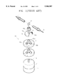
- a conventional controlling device of a tunable filter comprises a holder 8 in which a tunable filter 5 is installed, a DC servo-motor 11 for driving the tunable filter 5, an encoder 13 fixed to a rotating shaft 11a of the DC servo-motor 11, and reduction gears 15 for changing the rotational speed of the servo-motor 11 to a suitable speed.
- the encoder 13 measures the angle of disposition of the tunable filter 5 with respect to the incident rays by detecting the rotation angle of the DC servo-motor 11.
- the DC servo-motor 11 controls the angle of disposition of the tunable filter 5 with respect to the incident rays.
- the tunable filter 5 selectively transmits a ray of a specific wavelength among the rays emitted from a first optical fiber 1 and directs the selected rays to a second optical fiber 9.
- the reduction gears 15 installed between the DC servo-motor 11 and the tunable filter 5 include a center gear 17 fixed to the rotating shaft 11a of the DC servo-motor 11, first, second and third gears 18a, 18b and 18c meshed with the center gear 17, a ring gear 19 having teeth 19a on the inner circumferential surface thereof to mesh with the first, second and third gears 18a, 18b and 18c.
- a rotating shaft 19c provided at the center of a cover 19b of the ring gear 19 is fitted to the holder 8.
- a plurality of the reduction gears 15 as described above are provided.
- the first, second and third gears 18a, 18b and 18c meshed with the center gear 17 are simultaneously rotated. Since the first, second and third gears 18a, 18b and 18c are meshed with the ring gear 19, they revolve around the center gear 17.
- the ring gear 19 is rotated at a speed that is equivalent to the revolution speed of the first, second and third gears 18a, 18b and 18c.
- the ring gear 19 is rotated at a speed slower than that of the DC servo-motor 11, and at the same time the holder 8 fitted to the rotating shaft 19c of the ring gear 19 is rotated at the same slower speed, and therefore the angle of disposition of the tunable filter 5 can be finely controlled. Consequently, since the angle at which the tunable filter 5 is disposed can be appropriately controlled according to the value measured in the encoder 13, a ray of specific wavelength can be selectively transmitted.
- the controlling device of the tunable filter is provided with a plurality of reduction gears, the structure of the control device is complicated and the size of the whole controlling device is large.
- a controlling device of a tunable filter comprising: a base; a tunable filter disposed on the base along an optical path between first and second optical fibers; a holder rotatably installed on the base to support the tunable filter; a driving unit installed on the base for providing a rotational force; a speed reducing device having a worm gear extending from a rotating shaft of the driving unit and a movable member provided with a threaded hole engaged with the worm gear to allow reciprocal movement along the worm gear according to the rotation direction of the worm gear; and a rotating unit for rotating the holder in accordance with the linear movement of the movable member.
- the rotating unit comprises a lever having one end fixed to the holder and the other end contacting the movable member and pivoting around the one end in accordance with the linear movement of the movable member, and an elastic biasing unit elastically biasing the lever toward the movable member to keep the lever in contact with the movable member.
- the elastic biasing unit comprises a supporting member, one end of which contacts with the lever, a bracket provided on the base to slidingly support the supporting member, and a spring for pressing the supporting member of the lever to contact the movable member.
- the rotating unit comprises a connecting bar extending from one side of the movable member and having a connecting pin, and a connecting piece extending from one side of the holder and having a longitudinal slot for the connecting pin to be slidingly assembled therein.
- FIG. 1 is an exploded perspective view schematically illustrating a conventional controlling device of a tunable filter
- FIG. 2 is a perspective view schematically illustrating an embodiment of a controlling device of a tunable filter according to the present invention
- FIGS. 3 and 4 are partial cross-sectional views schematically illustrating the operation of the controlling device of the tunable filter of FIG. 2;
- FIG. 5 is a partial cross-sectional view schematically illustrating another embodiment of a controlling device of a tunable filter according to the present invention.
- FIG. 6 is a partial cross-sectional view schematically illustrating the controlling device of the tunable filter of FIG. 5 being operated.
- an embodiment of a controlling device of a tunable filter according to the present invention includes a base 101, a driving unit 110 installed on the base 101 for providing a rotational force. Also, an encoder 130 for measuring the rotation angle of the driving unit 110, and a speed reducing device 100 for transferring power from the driving unit 110 ultimately to a holder 141 with a predetermined reduction ratio are installed on the base.
- the driving unit 110 is provided with a motor, for example, a DC servo-motor.
- the encoder 130 is fixed to a shaft (not shown) of the driving unit 110 to measure the rotation angle of the driving unit 110.
- the speed reducing device 100 includes a worm gear 107 extending from the rotational shaft of the driving unit 110, and a movable member 105 provided with a threaded hole 105a engaged with the worm gear 107 and functions to transform the rotational movement of the driving unit 110 into a linear movement. Accordingly, the movable member 105 moves back and forth along a guide member 106 as the worm gear 107 rotates.
- the pitch of the thread of the worm gear 107 and threaded hole 105a is made finer, it is possible to change the rapid rotational movement of the driving unit 110 into a slower linear movement of the movable member 105.
- a tunable filter 5 as supported by the holder 141 is disposed between first and second optical fibers 1 and 9 which are installed on the base 101.
- the holder 141 is fixed to one end of a lever 140 the other end of the lever 140 moves in accordance with the movement of the movable member 105. In other words, as the movable member 105 moves, the lever 140 pivots around the one end of the lever 140 and consequently the holder 141 rotates as well.
- the lever 140 is biased toward the movable member 105 by an elastic biasing unit 150 to keep the lever 140 in contact with the movable member 105.
- the elastic biasing unit 150 comprises a supporting member 153 for supporting the lever 140, a spring 155 elastically biasing the supporting member 153 toward the lever 140, and a bracket 157 provided on the base 101 to slidingly support the supporting member 153.
- the lever 140 and the elastic biasing unit 150 acts to rotate the holder 141 in accordance with the linear movement of the movable member 105.
- the movable member 105 engaged with the worm gear 107 is moved forward along the guide member 106 as shown in FIG. 4.
- the lever 140 which is in contact with the movable member 105 pivots to rotate the holder 141, and accordingly, it is possible to control the angle of disposition of the tunable filter 5 with respect to the incident rays by rotating the tunable filter 5 supported by the holder 141.
- the tilt angle of the tunable filter 5 can be finely controlled.
- FIG. 5 Another embodiment of a controlling device of tunable filter according to the present invention is described with reference to FIG. 5.
- reference numerals that are the same as those shown in FIG. 2 denote similar members having the functions.
- a connecting bar 250 provided with a connecting pin 257 extends from one side of a movable member 105.
- a connecting piece 240 extends from one side of the holder 141 supporting a tunable filter 5 and has a longitudinal slot 253 for the connecting pin 257 of the movable member 105 to be slidingly assembled therein.
- the connecting piece 240 and the connecting bar 250 act to rotate the holder 141 in accordance with the linear movement of the movable member 105.
- the controlling devices of the tunable filter according to the present invention as described above can finely control the tunable filter by reducing the fast rotational movement of the driving unit to a slow movement of the holder by a simple speed reducing device comprised of a worm gear and a movable member. Therefore, the structure of the device is simple and the size of the device can be minimized.
Abstract
Description
Claims (4)
Applications Claiming Priority (4)
| Application Number | Priority Date | Filing Date | Title |
|---|---|---|---|
| KR97-21337 | 1997-05-28 | ||
| KR1019970021337A KR100213107B1 (en) | 1997-05-28 | 1997-05-28 | Tunner filter tunning apparatus |
| KR1019970026103A KR100238294B1 (en) | 1997-06-20 | 1997-06-20 | Adjusting apparatus of tunable filter |
| KR97-26103 | 1997-06-20 |
Publications (1)
| Publication Number | Publication Date |
|---|---|
| US5966987A true US5966987A (en) | 1999-10-19 |
Family
ID=26632772
Family Applications (1)
| Application Number | Title | Priority Date | Filing Date |
|---|---|---|---|
| US09/047,383 Expired - Fee Related US5966987A (en) | 1997-05-28 | 1998-03-25 | Controlling device of tunable filter |
Country Status (4)
| Country | Link |
|---|---|
| US (1) | US5966987A (en) |
| JP (1) | JPH10332982A (en) |
| CN (1) | CN1090761C (en) |
| BR (1) | BR9801209A (en) |
Cited By (6)
| Publication number | Priority date | Publication date | Assignee | Title |
|---|---|---|---|---|
| US6246818B1 (en) * | 1998-11-13 | 2001-06-12 | Fujitsu Limited | Tunable optical filter |
| US6378849B1 (en) | 2001-04-13 | 2002-04-30 | General Electric Company | Methods and apparatus for mounting motors |
| US6384978B1 (en) * | 1999-03-19 | 2002-05-07 | Qtera Corporation | Temperature-compensated optical filter assemblies and related methods |
| US20030138199A1 (en) * | 2002-01-18 | 2003-07-24 | June-Hyeon Ahn | Device and method for fixing an optical wavelength in a wavelength division multiplexing system |
| US20110063720A1 (en) * | 2009-09-15 | 2011-03-17 | Christopher Lin | Optical amplifiers using switched filter devices |
| US20120145872A1 (en) * | 2009-06-15 | 2012-06-14 | Toptica Photonics Ag | Kinematic mount |
Families Citing this family (4)
| Publication number | Priority date | Publication date | Assignee | Title |
|---|---|---|---|---|
| CN1936617B (en) * | 2006-10-12 | 2010-04-21 | 中国地震局地震研究所 | Comprehensive low-noise constant-temperature laser receiving system |
| CN102032947A (en) * | 2010-10-29 | 2011-04-27 | 上海理工大学 | Spectrograph sample bracket |
| JP5888775B2 (en) * | 2011-11-21 | 2016-03-22 | 株式会社 ファースト メカニカル デザイン | Optical fiber coupler |
| CN114967023A (en) * | 2022-04-26 | 2022-08-30 | 核工业理化工程研究院 | Quick-release type precision driving assembly and electric optical adjusting frame and adjusting method thereof |
Citations (11)
| Publication number | Priority date | Publication date | Assignee | Title |
|---|---|---|---|---|
| US2338271A (en) * | 1942-01-03 | 1944-01-04 | Ulanet Herman | Mechanical adjustment means |
| US3402613A (en) * | 1966-08-01 | 1968-09-24 | Trw Inc | Differential screw with variable adjustments |
| US3874245A (en) * | 1973-02-12 | 1975-04-01 | Moravskoslezska Armaturka Naro | Drive apparatus for rotary spindles |
| JPS61271521A (en) * | 1985-05-25 | 1986-12-01 | Tokyo Optical Co Ltd | Fine adjustment device for rotor |
| JPS62120423A (en) * | 1985-11-19 | 1987-06-01 | Kunio Kato | Continuous heat treating equipment |
| JPS63147135A (en) * | 1986-12-10 | 1988-06-20 | Konica Corp | Stabilizing device for quantity of laser light |
| US4825714A (en) * | 1984-10-25 | 1989-05-02 | Omron Tateisi Electronics Co. | Pivotal micromotion device |
| JPH02120716A (en) * | 1988-10-31 | 1990-05-08 | Asahi Optical Co Ltd | Optical axis fine adjustment device |
| US5327062A (en) * | 1991-09-30 | 1994-07-05 | Byers Edward R | Precision drive assembly for telescopes and other instruments |
| JPH06281813A (en) * | 1993-01-29 | 1994-10-07 | Nec Corp | Transmission wavelength variable device |
| US5646399A (en) * | 1995-08-28 | 1997-07-08 | Fujitsu Limited | Tunable optical filter having beam splitter and movable film filter |
-
1998
- 1998-03-25 US US09/047,383 patent/US5966987A/en not_active Expired - Fee Related
- 1998-03-30 BR BR9801209A patent/BR9801209A/en not_active Application Discontinuation
- 1998-04-09 JP JP10097938A patent/JPH10332982A/en active Pending
- 1998-04-22 CN CN98107311A patent/CN1090761C/en not_active Expired - Fee Related
Patent Citations (12)
| Publication number | Priority date | Publication date | Assignee | Title |
|---|---|---|---|---|
| US2338271A (en) * | 1942-01-03 | 1944-01-04 | Ulanet Herman | Mechanical adjustment means |
| US3402613A (en) * | 1966-08-01 | 1968-09-24 | Trw Inc | Differential screw with variable adjustments |
| US3874245A (en) * | 1973-02-12 | 1975-04-01 | Moravskoslezska Armaturka Naro | Drive apparatus for rotary spindles |
| US4825714A (en) * | 1984-10-25 | 1989-05-02 | Omron Tateisi Electronics Co. | Pivotal micromotion device |
| JPS61271521A (en) * | 1985-05-25 | 1986-12-01 | Tokyo Optical Co Ltd | Fine adjustment device for rotor |
| JPS62120423A (en) * | 1985-11-19 | 1987-06-01 | Kunio Kato | Continuous heat treating equipment |
| JPS63147135A (en) * | 1986-12-10 | 1988-06-20 | Konica Corp | Stabilizing device for quantity of laser light |
| JPH02120716A (en) * | 1988-10-31 | 1990-05-08 | Asahi Optical Co Ltd | Optical axis fine adjustment device |
| US5327062A (en) * | 1991-09-30 | 1994-07-05 | Byers Edward R | Precision drive assembly for telescopes and other instruments |
| JPH06281813A (en) * | 1993-01-29 | 1994-10-07 | Nec Corp | Transmission wavelength variable device |
| US5506920A (en) * | 1993-01-29 | 1996-04-09 | Nec Corporation | Optical wavelength tunable filter |
| US5646399A (en) * | 1995-08-28 | 1997-07-08 | Fujitsu Limited | Tunable optical filter having beam splitter and movable film filter |
Cited By (9)
| Publication number | Priority date | Publication date | Assignee | Title |
|---|---|---|---|---|
| US6246818B1 (en) * | 1998-11-13 | 2001-06-12 | Fujitsu Limited | Tunable optical filter |
| US6384978B1 (en) * | 1999-03-19 | 2002-05-07 | Qtera Corporation | Temperature-compensated optical filter assemblies and related methods |
| US6378849B1 (en) | 2001-04-13 | 2002-04-30 | General Electric Company | Methods and apparatus for mounting motors |
| US20030138199A1 (en) * | 2002-01-18 | 2003-07-24 | June-Hyeon Ahn | Device and method for fixing an optical wavelength in a wavelength division multiplexing system |
| US6936805B2 (en) * | 2002-01-18 | 2005-08-30 | Samsung Electronics Co., Ltd. | Device and method for fixing an optical wavelength in a wavelength division multiplexing system |
| US20120145872A1 (en) * | 2009-06-15 | 2012-06-14 | Toptica Photonics Ag | Kinematic mount |
| US9323025B2 (en) * | 2009-06-15 | 2016-04-26 | Toptica Photonics Ag | Kinematic mount |
| US20110063720A1 (en) * | 2009-09-15 | 2011-03-17 | Christopher Lin | Optical amplifiers using switched filter devices |
| US8294981B2 (en) * | 2009-09-15 | 2012-10-23 | Oclaro Technology Limited | Optical amplifiers using switched filter devices |
Also Published As
| Publication number | Publication date |
|---|---|
| BR9801209A (en) | 1999-06-15 |
| CN1200490A (en) | 1998-12-02 |
| JPH10332982A (en) | 1998-12-18 |
| CN1090761C (en) | 2002-09-11 |
Similar Documents
| Publication | Publication Date | Title |
|---|---|---|
| US4378144A (en) | Optical switch | |
| US5966987A (en) | Controlling device of tunable filter | |
| JP2597707B2 (en) | Lens barrel | |
| US5196963A (en) | Zoom lens device | |
| JP3501176B2 (en) | Lens barrel with built-in surface wave motor | |
| US6038404A (en) | Lens barrel for a camera having a non-rotatable cam ring moved by a feed screw | |
| GB2304067A (en) | Electric hammer drill | |
| US5177524A (en) | Device for controlling automatic focusing lens device | |
| US5790319A (en) | Lens barrel | |
| FR2641089A1 (en) | ||
| US5506731A (en) | Device for controllably moving an optical element | |
| KR100213107B1 (en) | Tunner filter tunning apparatus | |
| JP3544242B2 (en) | Coarse adjustment device and precision adjustment device for objective lens | |
| KR100238294B1 (en) | Adjusting apparatus of tunable filter | |
| US5898528A (en) | Lens barrel with built-in ultrasonic motor | |
| KR0118095Y1 (en) | Zoom camera | |
| CA1142003A (en) | Optical switch | |
| CA2118166C (en) | Device for controllably moving an optical element | |
| US3936795A (en) | Combined variable resistor assembly provided with tap position indicator means | |
| US6088538A (en) | Zoom finder | |
| US5983034A (en) | Lens barrel having a surface wave motor | |
| US5072255A (en) | Optically variable magnification mechanism | |
| US4718786A (en) | Transport device for a print unit of printing machines | |
| JPH118785A (en) | Driving device for photographing lens | |
| KR900004897B1 (en) | Switching device for pinch-roller |
Legal Events
| Date | Code | Title | Description |
|---|---|---|---|
| AS | Assignment |
Owner name: SAMSUNG ELECTRONICS CO., LTD., KOREA, REPUBLIC OF Free format text: ASSIGNMENT OF ASSIGNORS INTEREST;ASSIGNORS:YOON, YEUNG-IYUL;JUNG, TAE-SAN;SONG, YOUNG-JIN;REEL/FRAME:009246/0988 Effective date: 19980528 |
|
| FEPP | Fee payment procedure |
Free format text: PAYOR NUMBER ASSIGNED (ORIGINAL EVENT CODE: ASPN); ENTITY STATUS OF PATENT OWNER: LARGE ENTITY |
|
| FPAY | Fee payment |
Year of fee payment: 4 |
|
| REMI | Maintenance fee reminder mailed | ||
| LAPS | Lapse for failure to pay maintenance fees | ||
| STCH | Information on status: patent discontinuation |
Free format text: PATENT EXPIRED DUE TO NONPAYMENT OF MAINTENANCE FEES UNDER 37 CFR 1.362 |
|
| FP | Lapsed due to failure to pay maintenance fee |
Effective date: 20071019 |