US5889246A - Automotive brake switch - Google Patents
Automotive brake switch Download PDFInfo
- Publication number
- US5889246A US5889246A US08/782,215 US78221597A US5889246A US 5889246 A US5889246 A US 5889246A US 78221597 A US78221597 A US 78221597A US 5889246 A US5889246 A US 5889246A
- Authority
- US
- United States
- Prior art keywords
- carriage
- plunger
- switch
- lever arm
- brake
- Prior art date
- Legal status (The legal status is an assumption and is not a legal conclusion. Google has not performed a legal analysis and makes no representation as to the accuracy of the status listed.)
- Expired - Fee Related
Links
- 238000000034 method Methods 0.000 claims description 5
- 230000006835 compression Effects 0.000 claims description 2
- 238000007906 compression Methods 0.000 claims description 2
- 238000009434 installation Methods 0.000 abstract description 17
- 230000007935 neutral effect Effects 0.000 abstract description 5
- 230000001419 dependent effect Effects 0.000 description 2
- 238000003825 pressing Methods 0.000 description 2
- 208000032953 Device battery issue Diseases 0.000 description 1
- 238000005452 bending Methods 0.000 description 1
- 238000010276 construction Methods 0.000 description 1
- 230000000694 effects Effects 0.000 description 1
- 231100001261 hazardous Toxicity 0.000 description 1
- 230000003993 interaction Effects 0.000 description 1
- 230000007257 malfunction Effects 0.000 description 1
- 238000004519 manufacturing process Methods 0.000 description 1
- 230000013011 mating Effects 0.000 description 1
- 230000000717 retained effect Effects 0.000 description 1
Images


Classifications
-
- H—ELECTRICITY
- H01—ELECTRIC ELEMENTS
- H01H—ELECTRIC SWITCHES; RELAYS; SELECTORS; EMERGENCY PROTECTIVE DEVICES
- H01H3/00—Mechanisms for operating contacts
- H01H3/02—Operating parts, i.e. for operating driving mechanism by a mechanical force external to the switch
- H01H3/16—Operating parts, i.e. for operating driving mechanism by a mechanical force external to the switch adapted for actuation at a limit or other predetermined position in the path of a body, the relative movement of switch and body being primarily for a purpose other than the actuation of the switch, e.g. for a door switch, a limit switch, a floor-levelling switch of a lift
- H01H3/166—Self-adjusting mountings, transmissions and the like
- H01H2003/167—Self-adjusting mountings, transmissions and the like with locking of the adjusted parts in the adjusted position by a separate action
Definitions
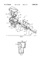
- the switch is mounted to the mounting plate, as described above, by locking the mounting flange between the projecting tangs 53 of the sleeve and the wall 91 of the switch body.
- the plunger pressingly engages the striker plate 74. Since the C-clamp 91 is maintained in an open position by extension 63 of the lever arm, the plunger moves axially into the cylindrical slotted section 82 of the carriage.
- the switch arm contacting section 83 of the carriage is profiled to form sloping cams, the cams 31, 33, and 35 being typical. With axial movement of the carriage within the housing, the cams pressingly engage the switch arms and the butt contacts.
- FIG. 4A With the brakes in the at rest or in the "off" position, it may be seen that the cam 31 is not in contact with switch arm 39 associated with butt contact 34.
- the cam 33 is similarly out of contact with switch arm 41 associated with butt contact 32.
- the cam 35 is in contact with switch arm 43, thus opening the connection between the switch arm 43 and butt contact 36 and, for example, deenergizing the stop lamps.
Abstract
Description
Claims (13)
Priority Applications (1)
| Application Number | Priority Date | Filing Date | Title |
|---|---|---|---|
| US08/782,215 US5889246A (en) | 1997-01-13 | 1997-01-13 | Automotive brake switch |
Applications Claiming Priority (1)
| Application Number | Priority Date | Filing Date | Title |
|---|---|---|---|
| US08/782,215 US5889246A (en) | 1997-01-13 | 1997-01-13 | Automotive brake switch |
Publications (1)
| Publication Number | Publication Date |
|---|---|
| US5889246A true US5889246A (en) | 1999-03-30 |
Family
ID=25125367
Family Applications (1)
| Application Number | Title | Priority Date | Filing Date |
|---|---|---|---|
| US08/782,215 Expired - Fee Related US5889246A (en) | 1997-01-13 | 1997-01-13 | Automotive brake switch |
Country Status (1)
| Country | Link |
|---|---|
| US (1) | US5889246A (en) |
Cited By (8)
| Publication number | Priority date | Publication date | Assignee | Title |
|---|---|---|---|---|
| EP1111632A1 (en) * | 1999-12-21 | 2001-06-27 | Methode Electronics Malta Ltd. | Switch, in particular self-adjusting pedal-box switch |
| US20050023117A1 (en) * | 2002-08-23 | 2005-02-03 | Noriyuki Kasakawa | Stoplight switch and mounting method |
| US20060231374A1 (en) * | 2005-04-14 | 2006-10-19 | Braaten Ronald J | Hand and foot switch |
| CN101329956B (en) * | 2007-06-22 | 2011-09-28 | 长盛科技股份有限公司 | Switch device for turnon and turndown circuit of vehicle |
| US20120111138A1 (en) * | 2010-11-08 | 2012-05-10 | Toyota Motor Engineering & Manufacturing North America, Inc. | High Load Resistant Stop Lamp Switch Brackets and Brake Pedal Assemblies Incorporating the Same |
| US8615870B1 (en) | 2009-11-05 | 2013-12-31 | Honda Motor Co., Ltd. | Method for installing cruise control stop switch |
| US20150035349A1 (en) * | 2013-07-30 | 2015-02-05 | Mitsubishi Jidosha Kogyo Kabushiki Kaisha | Brake control device |
| CN106229173A (en) * | 2016-08-30 | 2016-12-14 | 创景传感工业(惠州)有限公司 | A kind of door puts in place and detects switch |
Citations (3)
| Publication number | Priority date | Publication date | Assignee | Title |
|---|---|---|---|---|
| US4239947A (en) * | 1978-11-09 | 1980-12-16 | Stewart-Warner Corporation | Cruise control switch assembly |
| US4316065A (en) * | 1978-11-10 | 1982-02-16 | Trw Inc. | Plunger switch |
| US5162625A (en) * | 1991-01-22 | 1992-11-10 | Eaton Corporation | Switch assembly |
-
1997
- 1997-01-13 US US08/782,215 patent/US5889246A/en not_active Expired - Fee Related
Patent Citations (3)
| Publication number | Priority date | Publication date | Assignee | Title |
|---|---|---|---|---|
| US4239947A (en) * | 1978-11-09 | 1980-12-16 | Stewart-Warner Corporation | Cruise control switch assembly |
| US4316065A (en) * | 1978-11-10 | 1982-02-16 | Trw Inc. | Plunger switch |
| US5162625A (en) * | 1991-01-22 | 1992-11-10 | Eaton Corporation | Switch assembly |
Cited By (12)
| Publication number | Priority date | Publication date | Assignee | Title |
|---|---|---|---|---|
| EP1111632A1 (en) * | 1999-12-21 | 2001-06-27 | Methode Electronics Malta Ltd. | Switch, in particular self-adjusting pedal-box switch |
| US20050023117A1 (en) * | 2002-08-23 | 2005-02-03 | Noriyuki Kasakawa | Stoplight switch and mounting method |
| US6919520B2 (en) * | 2002-08-23 | 2005-07-19 | Matsushita Electric Industrial Co., Ltd. | Stoplight switch and mounting method |
| US20060231374A1 (en) * | 2005-04-14 | 2006-10-19 | Braaten Ronald J | Hand and foot switch |
| US7323646B2 (en) * | 2005-04-14 | 2008-01-29 | Conntrol International, Inc. | Hand and foot switch |
| CN101329956B (en) * | 2007-06-22 | 2011-09-28 | 长盛科技股份有限公司 | Switch device for turnon and turndown circuit of vehicle |
| US8615870B1 (en) | 2009-11-05 | 2013-12-31 | Honda Motor Co., Ltd. | Method for installing cruise control stop switch |
| US20120111138A1 (en) * | 2010-11-08 | 2012-05-10 | Toyota Motor Engineering & Manufacturing North America, Inc. | High Load Resistant Stop Lamp Switch Brackets and Brake Pedal Assemblies Incorporating the Same |
| US8550412B2 (en) * | 2010-11-08 | 2013-10-08 | Toyota Motor Engineering And Manufacturing North America, Inc. | High load resistant stop lamp switch brackets and brake pedal assemblies incorporating the same |
| US20150035349A1 (en) * | 2013-07-30 | 2015-02-05 | Mitsubishi Jidosha Kogyo Kabushiki Kaisha | Brake control device |
| US9308897B2 (en) * | 2013-07-30 | 2016-04-12 | Mitsubishi Jidosha Kogyo Kabushiki Kaisha | Brake control device |
| CN106229173A (en) * | 2016-08-30 | 2016-12-14 | 创景传感工业(惠州)有限公司 | A kind of door puts in place and detects switch |
Similar Documents
| Publication | Publication Date | Title |
|---|---|---|
| US4887702A (en) | Brake/shift interlock for an automatic transmission shift control mechanism | |
| US4297550A (en) | Method and construction for vehicle brake pedal and switch assembly | |
| US4967046A (en) | Automotive contact switch arrangement with essentially planar switch springs | |
| US5889246A (en) | Automotive brake switch | |
| CA2173275A1 (en) | Fuel filler door actuator assembly with integral kick-out spring | |
| US9916952B2 (en) | Carrier sub-assembly for an electrical relay device | |
| US4604506A (en) | Self-adjusting switch mechanism | |
| US4516748A (en) | Quick connect cylinder mount stucture | |
| US5947268A (en) | Self adjusting electric tappet switch | |
| GB2282005A (en) | Plunger switch | |
| MXPA98001220A (en) | Mue brake actuator release tool | |
| US6653582B2 (en) | Stop lamp switch and method for attaching the same | |
| US4742193A (en) | Retaining device for hydraulic master cylinder switch | |
| US6105732A (en) | Positive lock parking brake assembly | |
| CA2093363C (en) | Self-adjusting multicircuit brake switch | |
| US6109414A (en) | Shift lever device | |
| JPS59743B2 (en) | brake actuator | |
| US5636562A (en) | Spring brake actuator with release tool requiring limited axial space | |
| US4719444A (en) | Hydraulic master cylinder switch | |
| US5897173A (en) | Control assembly for providing redundant control outputs for operating a parking brake system | |
| KR970004738B1 (en) | Structure of stop lamp switch of a car | |
| US4597686A (en) | Quick release connecting assembly | |
| US5224588A (en) | Plunger switch providing relief for an excess plunger load | |
| US20240052926A1 (en) | Emergency Release of a Parking Gear | |
| JP2005534878A (en) | Cable-driven drum brake |
Legal Events
| Date | Code | Title | Description |
|---|---|---|---|
| AS | Assignment |
Owner name: JOSEPH POLLAK CORPORATION, MASSACHUSETTS Free format text: ASSIGNMENT OF ASSIGNORS INTEREST;ASSIGNORS:FRANK, CARL;SUSSER, MARK;GRIMES, MARK S.;REEL/FRAME:008434/0522;SIGNING DATES FROM 19961219 TO 19970108 |
|
| AS | Assignment |
Owner name: NATIONAL CITY BANK, OHIO Free format text: ASSIGNMENT OF ASSIGNORS INTEREST;ASSIGNOR:STONERIDGE, INC.;REEL/FRAME:009798/0228 Effective date: 19981230 |
|
| AS | Assignment |
Owner name: STONERIDGE CONTROL DEVICES, INC. A CORPORATION OF Free format text: ASSIGNMENT OF ASSIGNORS INTEREST;ASSIGNOR:STONERIDGE, INC. A CORPORATION OF OHIO;REEL/FRAME:010655/0117 Effective date: 19991231 |
|
| FPAY | Fee payment |
Year of fee payment: 4 |
|
| AS | Assignment |
Owner name: NATIONAL CITY BANK, OHIO Free format text: SECURITY AGREEMENT AND COLLATERAL AGREEMENT;ASSIGNOR:STONERIDGE CONTROL DEVICES, INC.;REEL/FRAME:013081/0095 Effective date: 20020501 |
|
| FPAY | Fee payment |
Year of fee payment: 8 |
|
| AS | Assignment |
Owner name: WILMINGTON TRUST COMPANY, DELAWARE Free format text: GRANT OF SECURITY INTEREST IN PATENT RIGHTS - FIRST PRIORITY;ASSIGNOR:CHRYSLER LLC;REEL/FRAME:019773/0001 Effective date: 20070803 Owner name: WILMINGTON TRUST COMPANY,DELAWARE Free format text: GRANT OF SECURITY INTEREST IN PATENT RIGHTS - FIRST PRIORITY;ASSIGNOR:CHRYSLER LLC;REEL/FRAME:019773/0001 Effective date: 20070803 |
|
| AS | Assignment |
Owner name: WILMINGTON TRUST COMPANY, DELAWARE Free format text: GRANT OF SECURITY INTEREST IN PATENT RIGHTS - SECOND PRIORITY;ASSIGNOR:CHRYSLER LLC;REEL/FRAME:019767/0810 Effective date: 20070803 Owner name: WILMINGTON TRUST COMPANY,DELAWARE Free format text: GRANT OF SECURITY INTEREST IN PATENT RIGHTS - SECOND PRIORITY;ASSIGNOR:CHRYSLER LLC;REEL/FRAME:019767/0810 Effective date: 20070803 |
|
| AS | Assignment |
Owner name: STONERIDGE CONTROL DEVICES, INC., MASSACHUSETTS Free format text: TERMINATION AND RELEASE OF ALL SECURITY INTERESTS IN PATENTS;ASSIGNOR:NATIONAL CITY BANK;REEL/FRAME:020098/0373 Effective date: 20071102 Owner name: NATIONAL CITY BUSINESS CREDIT, INC., OHIO Free format text: SECURITY AGREEMENT;ASSIGNORS:STONERIDGE, INC.;STONERIDGE ELECTRONICS, INC.;STONERIDGE CONTROL DEVICES, INC.;AND OTHERS;REEL/FRAME:020098/0378 Effective date: 20071102 Owner name: NATIONAL CITY BUSINESS CREDIT, INC.,OHIO Free format text: SECURITY AGREEMENT;ASSIGNORS:STONERIDGE, INC.;STONERIDGE ELECTRONICS, INC.;STONERIDGE CONTROL DEVICES, INC.;AND OTHERS;REEL/FRAME:020098/0378 Effective date: 20071102 |
|
| AS | Assignment |
Owner name: CHRYSLER LLC, MICHIGAN Free format text: TERMINATION AND RELEASE OF SECURITY INTEREST IN PATENT RIGHTS - SECOND PRIORITY;ASSIGNOR:WILMINGTON TRUST COMPANY;REEL/FRAME:020279/0099 Effective date: 20071219 Owner name: CHRYSLER LLC, MICHIGAN Free format text: TERMINATION AND RELEASE OF SECURITY INTEREST IN PATENT RIGHTS - FIRST PRIORITY;ASSIGNOR:WILMINGTON TRUST COMPANY;REEL/FRAME:020279/0084 Effective date: 20071219 |
|
| AS | Assignment |
Owner name: WILMINGTON TRUST COMPANY, DELAWARE Free format text: GRANT OF SECURITY INTEREST IN PATENT RIGHTS - FIRST PRIORITY;ASSIGNOR:CHRYSLER LLC;REEL/FRAME:020507/0166 Effective date: 20070803 Owner name: WILMINGTON TRUST COMPANY, DELAWARE Free format text: GRANT OF SECURITY INTEREST IN PATENT RIGHTS - SECOND PRIORITY;ASSIGNOR:CHRYSLER LLC;REEL/FRAME:020507/0206 Effective date: 20070803 Owner name: WILMINGTON TRUST COMPANY,DELAWARE Free format text: GRANT OF SECURITY INTEREST IN PATENT RIGHTS - FIRST PRIORITY;ASSIGNOR:CHRYSLER LLC;REEL/FRAME:020507/0166 Effective date: 20070803 Owner name: WILMINGTON TRUST COMPANY,DELAWARE Free format text: GRANT OF SECURITY INTEREST IN PATENT RIGHTS - SECOND PRIORITY;ASSIGNOR:CHRYSLER LLC;REEL/FRAME:020507/0206 Effective date: 20070803 |
|
| AS | Assignment |
Owner name: DAIMLERCHRYSLER COMPANY LLC, MICHIGAN Free format text: CHANGE OF NAME;ASSIGNOR:DAIMLERCHRYSLER CORPORATION;REEL/FRAME:021832/0886 Effective date: 20070329 Owner name: CHRYSLER LLC, MICHIGAN Free format text: CHANGE OF NAME;ASSIGNOR:DAIMLERCHRYSLER COMPANY LLC;REEL/FRAME:021832/0900 Effective date: 20070727 |
|
| AS | Assignment |
Owner name: US DEPARTMENT OF THE TREASURY, DISTRICT OF COLUMBI Free format text: GRANT OF SECURITY INTEREST IN PATENT RIGHTS - THIR;ASSIGNOR:CHRYSLER LLC;REEL/FRAME:022259/0188 Effective date: 20090102 Owner name: US DEPARTMENT OF THE TREASURY, DISTRICT OF COLUMBI Free format text: GRANT OF SECURITY INTEREST IN PATENT RIGHTS - THIR;ASSIGNOR:CHRYSLER LLC;REEL/FRAME:022259/0188B Effective date: 20090102 Owner name: US DEPARTMENT OF THE TREASURY,DISTRICT OF COLUMBIA Free format text: GRANT OF SECURITY INTEREST IN PATENT RIGHTS - THIR;ASSIGNOR:CHRYSLER LLC;REEL/FRAME:022259/0188 Effective date: 20090102 |
|
| AS | Assignment |
Owner name: CHRYSLER LLC, MICHIGAN Free format text: RELEASE BY SECURED PARTY;ASSIGNOR:US DEPARTMENT OF THE TREASURY;REEL/FRAME:022910/0273 Effective date: 20090608 |
|
| AS | Assignment |
Owner name: CHRYSLER LLC, MICHIGAN Free format text: RELEASE OF SECURITY INTEREST IN PATENT RIGHTS - FIRST PRIORITY;ASSIGNOR:WILMINGTON TRUST COMPANY;REEL/FRAME:022910/0498 Effective date: 20090604 Owner name: CHRYSLER LLC, MICHIGAN Free format text: RELEASE OF SECURITY INTEREST IN PATENT RIGHTS - SECOND PRIORITY;ASSIGNOR:WILMINGTON TRUST COMPANY;REEL/FRAME:022910/0740 Effective date: 20090604 Owner name: NEW CARCO ACQUISITION LLC, MICHIGAN Free format text: ASSIGNMENT OF ASSIGNORS INTEREST;ASSIGNOR:CHRYSLER LLC;REEL/FRAME:022915/0001 Effective date: 20090610 Owner name: THE UNITED STATES DEPARTMENT OF THE TREASURY, DIST Free format text: SECURITY AGREEMENT;ASSIGNOR:NEW CARCO ACQUISITION LLC;REEL/FRAME:022915/0489 Effective date: 20090610 Owner name: CHRYSLER LLC,MICHIGAN Free format text: RELEASE OF SECURITY INTEREST IN PATENT RIGHTS - FIRST PRIORITY;ASSIGNOR:WILMINGTON TRUST COMPANY;REEL/FRAME:022910/0498 Effective date: 20090604 Owner name: CHRYSLER LLC,MICHIGAN Free format text: RELEASE OF SECURITY INTEREST IN PATENT RIGHTS - SECOND PRIORITY;ASSIGNOR:WILMINGTON TRUST COMPANY;REEL/FRAME:022910/0740 Effective date: 20090604 Owner name: NEW CARCO ACQUISITION LLC,MICHIGAN Free format text: ASSIGNMENT OF ASSIGNORS INTEREST;ASSIGNOR:CHRYSLER LLC;REEL/FRAME:022915/0001 Effective date: 20090610 Owner name: THE UNITED STATES DEPARTMENT OF THE TREASURY,DISTR Free format text: SECURITY AGREEMENT;ASSIGNOR:NEW CARCO ACQUISITION LLC;REEL/FRAME:022915/0489 Effective date: 20090610 |
|
| AS | Assignment |
Owner name: CHRYSLER GROUP LLC, MICHIGAN Free format text: CHANGE OF NAME;ASSIGNOR:NEW CARCO ACQUISITION LLC;REEL/FRAME:022919/0126 Effective date: 20090610 Owner name: CHRYSLER GROUP LLC,MICHIGAN Free format text: CHANGE OF NAME;ASSIGNOR:NEW CARCO ACQUISITION LLC;REEL/FRAME:022919/0126 Effective date: 20090610 |
|
| AS | Assignment |
Owner name: THE BANK OF NEW YORK MELLON TRUST COMPANY, N.A., A Free format text: SECURITY AGREEMENT;ASSIGNOR:STONERIDGE CONTROL DEVICES, INC.;REEL/FRAME:025105/0078 Effective date: 20101004 |
|
| REMI | Maintenance fee reminder mailed | ||
| LAPS | Lapse for failure to pay maintenance fees | ||
| STCH | Information on status: patent discontinuation |
Free format text: PATENT EXPIRED DUE TO NONPAYMENT OF MAINTENANCE FEES UNDER 37 CFR 1.362 |
|
| FP | Lapsed due to failure to pay maintenance fee |
Effective date: 20110330 |
|
| AS | Assignment |
Owner name: CHRYSLER GROUP LLC, MICHIGAN Free format text: RELEASE BY SECURED PARTY;ASSIGNOR:THE UNITED STATES DEPARTMENT OF THE TREASURY;REEL/FRAME:026343/0298 Effective date: 20110524 Owner name: CHRYSLER GROUP GLOBAL ELECTRIC MOTORCARS LLC, NORT Free format text: RELEASE BY SECURED PARTY;ASSIGNOR:THE UNITED STATES DEPARTMENT OF THE TREASURY;REEL/FRAME:026343/0298 Effective date: 20110524 |
|
| AS | Assignment |
Owner name: CITIBANK, N.A., NEW YORK Free format text: SECURITY AGREEMENT;ASSIGNOR:CHRYSLER GROUP LLC;REEL/FRAME:026404/0123 Effective date: 20110524 |
|
| AS | Assignment |
Owner name: CITIBANK, N.A., NEW YORK Free format text: SECURITY AGREEMENT;ASSIGNOR:CHRYSLER GROUP LLC;REEL/FRAME:026435/0652 Effective date: 20110524 |
|
| AS | Assignment |
Owner name: PNC BANK, NATIONAL ASSOCIATION, AS AGENT, OHIO Free format text: AMENDED AND RESTATED PATENT SECURITY AGREEMENT;ASSIGNORS:STONERIDGE, INC.;STONERIDGE ELECTRONICS, INC.;STONERIDGE CONTROL DEVICES, INC.;REEL/FRAME:027328/0797 Effective date: 20111201 |
|
| AS | Assignment |
Owner name: JPMORGAN CHASE BANK, N.A., ILLINOIS Free format text: SECURITY AGREEMENT;ASSIGNOR:CHRYSLER GROUP LLC;REEL/FRAME:032384/0640 Effective date: 20140207 |
|
| AS | Assignment |
Owner name: STONERIDGE CONTROL DEVICES, INC., MASSACHUSETTS Free format text: RELEASE BY SECURED PARTY;ASSIGNOR:THE BANK OF NEW YORK MELLON TRUST COMPANY, N.A.;REEL/FRAME:033998/0222 Effective date: 20141015 |
|
| AS | Assignment |
Owner name: FCA US LLC, MICHIGAN Free format text: CHANGE OF NAME;ASSIGNOR:CHRYSLER GROUP LLC;REEL/FRAME:035553/0356 Effective date: 20141203 |
|
| AS | Assignment |
Owner name: FCA US LLC, FORMERLY KNOWN AS CHRYSLER GROUP LLC, Free format text: RELEASE OF SECURITY INTEREST RELEASING SECOND-LIEN SECURITY INTEREST PREVIOUSLY RECORDED AT REEL 026426 AND FRAME 0644, REEL 026435 AND FRAME 0652, AND REEL 032384 AND FRAME 0591;ASSIGNOR:CITIBANK, N.A.;REEL/FRAME:037784/0001 Effective date: 20151221 |
|
| AS | Assignment |
Owner name: FCA US LLC (FORMERLY KNOWN AS CHRYSLER GROUP LLC), Free format text: RELEASE BY SECURED PARTY;ASSIGNOR:CITIBANK, N.A.;REEL/FRAME:042885/0255 Effective date: 20170224 |
|
| AS | Assignment |
Owner name: FCA US LLC (FORMERLY KNOWN AS CHRYSLER GROUP LLC), Free format text: RELEASE BY SECURED PARTY;ASSIGNOR:JPMORGAN CHASE BANK, N.A.;REEL/FRAME:048177/0356 Effective date: 20181113 |