US5850849A - Storage tank shutoff valve with double cam assembly - Google Patents
Storage tank shutoff valve with double cam assembly Download PDFInfo
- Publication number
- US5850849A US5850849A US08/486,813 US48681395A US5850849A US 5850849 A US5850849 A US 5850849A US 48681395 A US48681395 A US 48681395A US 5850849 A US5850849 A US 5850849A
- Authority
- US
- United States
- Prior art keywords
- assembly
- valve
- shutoff valve
- housing
- storage tank
- Prior art date
- Legal status (The legal status is an assumption and is not a legal conclusion. Google has not performed a legal analysis and makes no representation as to the accuracy of the status listed.)
- Expired - Lifetime
Links
Images


Classifications
-
- B—PERFORMING OPERATIONS; TRANSPORTING
- B65—CONVEYING; PACKING; STORING; HANDLING THIN OR FILAMENTARY MATERIAL
- B65D—CONTAINERS FOR STORAGE OR TRANSPORT OF ARTICLES OR MATERIALS, e.g. BAGS, BARRELS, BOTTLES, BOXES, CANS, CARTONS, CRATES, DRUMS, JARS, TANKS, HOPPERS, FORWARDING CONTAINERS; ACCESSORIES, CLOSURES, OR FITTINGS THEREFOR; PACKAGING ELEMENTS; PACKAGES
- B65D90/00—Component parts, details or accessories for large containers
- B65D90/22—Safety features
- B65D90/26—Overfill prevention
-
- B—PERFORMING OPERATIONS; TRANSPORTING
- B67—OPENING, CLOSING OR CLEANING BOTTLES, JARS OR SIMILAR CONTAINERS; LIQUID HANDLING
- B67D—DISPENSING, DELIVERING OR TRANSFERRING LIQUIDS, NOT OTHERWISE PROVIDED FOR
- B67D7/00—Apparatus or devices for transferring liquids from bulk storage containers or reservoirs into vehicles or into portable containers, e.g. for retail sale purposes
- B67D7/06—Details or accessories
- B67D7/36—Arrangements of flow- or pressure-control valves
- B67D7/362—Arrangements of flow- or pressure-control valves combined with over-fill preventing means
- B67D7/365—Arrangements of flow- or pressure-control valves combined with over-fill preventing means using floats
-
- F—MECHANICAL ENGINEERING; LIGHTING; HEATING; WEAPONS; BLASTING
- F16—ENGINEERING ELEMENTS AND UNITS; GENERAL MEASURES FOR PRODUCING AND MAINTAINING EFFECTIVE FUNCTIONING OF MACHINES OR INSTALLATIONS; THERMAL INSULATION IN GENERAL
- F16K—VALVES; TAPS; COCKS; ACTUATING-FLOATS; DEVICES FOR VENTING OR AERATING
- F16K31/00—Actuating devices; Operating means; Releasing devices
- F16K31/12—Actuating devices; Operating means; Releasing devices actuated by fluid
- F16K31/18—Actuating devices; Operating means; Releasing devices actuated by fluid actuated by a float
- F16K31/20—Actuating devices; Operating means; Releasing devices actuated by fluid actuated by a float actuating a lift valve
- F16K31/24—Actuating devices; Operating means; Releasing devices actuated by fluid actuated by a float actuating a lift valve with a transmission with parts linked together from a single float to a single valve
- F16K31/26—Actuating devices; Operating means; Releasing devices actuated by fluid actuated by a float actuating a lift valve with a transmission with parts linked together from a single float to a single valve with the valve guided for rectilinear movement and the float attached to a pivoted arm
-
- Y—GENERAL TAGGING OF NEW TECHNOLOGICAL DEVELOPMENTS; GENERAL TAGGING OF CROSS-SECTIONAL TECHNOLOGIES SPANNING OVER SEVERAL SECTIONS OF THE IPC; TECHNICAL SUBJECTS COVERED BY FORMER USPC CROSS-REFERENCE ART COLLECTIONS [XRACs] AND DIGESTS
- Y10—TECHNICAL SUBJECTS COVERED BY FORMER USPC
- Y10T—TECHNICAL SUBJECTS COVERED BY FORMER US CLASSIFICATION
- Y10T137/00—Fluid handling
- Y10T137/7287—Liquid level responsive or maintaining systems
- Y10T137/7358—By float controlled valve
- Y10T137/7368—Servo relay operation of control
- Y10T137/7371—Fluid pressure
-
- Y—GENERAL TAGGING OF NEW TECHNOLOGICAL DEVELOPMENTS; GENERAL TAGGING OF CROSS-SECTIONAL TECHNOLOGIES SPANNING OVER SEVERAL SECTIONS OF THE IPC; TECHNICAL SUBJECTS COVERED BY FORMER USPC CROSS-REFERENCE ART COLLECTIONS [XRACs] AND DIGESTS
- Y10—TECHNICAL SUBJECTS COVERED BY FORMER USPC
- Y10T—TECHNICAL SUBJECTS COVERED BY FORMER US CLASSIFICATION
- Y10T137/00—Fluid handling
- Y10T137/7287—Liquid level responsive or maintaining systems
- Y10T137/7358—By float controlled valve
- Y10T137/7381—Quick acting
- Y10T137/74—Lost motion mechanism
-
- Y—GENERAL TAGGING OF NEW TECHNOLOGICAL DEVELOPMENTS; GENERAL TAGGING OF CROSS-SECTIONAL TECHNOLOGIES SPANNING OVER SEVERAL SECTIONS OF THE IPC; TECHNICAL SUBJECTS COVERED BY FORMER USPC CROSS-REFERENCE ART COLLECTIONS [XRACs] AND DIGESTS
- Y10—TECHNICAL SUBJECTS COVERED BY FORMER USPC
- Y10T—TECHNICAL SUBJECTS COVERED BY FORMER US CLASSIFICATION
- Y10T137/00—Fluid handling
- Y10T137/7287—Liquid level responsive or maintaining systems
- Y10T137/7358—By float controlled valve
- Y10T137/7423—Rectilinearly traveling float
- Y10T137/7426—Float co-axial with valve or port
-
- Y—GENERAL TAGGING OF NEW TECHNOLOGICAL DEVELOPMENTS; GENERAL TAGGING OF CROSS-SECTIONAL TECHNOLOGIES SPANNING OVER SEVERAL SECTIONS OF THE IPC; TECHNICAL SUBJECTS COVERED BY FORMER USPC CROSS-REFERENCE ART COLLECTIONS [XRACs] AND DIGESTS
- Y10—TECHNICAL SUBJECTS COVERED BY FORMER USPC
- Y10T—TECHNICAL SUBJECTS COVERED BY FORMER US CLASSIFICATION
- Y10T137/00—Fluid handling
- Y10T137/7287—Liquid level responsive or maintaining systems
- Y10T137/7358—By float controlled valve
- Y10T137/7439—Float arm operated valve
- Y10T137/7478—With interposed cam, gear or threaded connection
Definitions
- the present invention relates generally to valves and more particularly to a shutoff valve assembly for automatically cutting off flow of a liquid to a storage tank in response to a predetermined fluid level in the storage tank.
- the invention is specifically disclosed in connection with a valve assembly that is especially adapted for use with viscous fluids in a pressurized supply line, minimizes line shock in the fluid supply line during valve closing, and completely closes the valve.
- liquid storage tanks for such fluids as gasoline, diesel fuel, and oil.
- These storage tanks are usually filled through openings that extend upwardly from the top of the tanks.
- Such openings usually have relatively small diameters that are sized to receive a dispensing tube, which dispensing tube is connected to a tank truck or other supply source.
- these storage tanks do not have gauges and the operator filling the storage tank has no visual view of the internal space of the storage tank, or any other reliable way of determining when the storage tank is approaching a full level. Consequently, overfilling of storage tanks is a common occurrence and may result in spillage of the tank contents, damage to the tank or filling equipment, or injury to persons.
- shutoff valves One way to automatically shutoff the flow of liquid to a full storage tank that has been employed in the prior art is to place a shutoff valve in the dispensing line used for supplying liquid to the storage tank.
- These types of shutoff valves usually employ floats that are moved by a rising liquid level in the tanks. The movement of the floats is, in turn, used to move a closure element in the shutoff valve from an open position to a closed position that stops or significantly reduces the flow of fluid through the drop tube. Examples of such shutoff valves in drop tubes are illustrated in U.S. Pat. No. 4,986,320 to Kesterman et al. and U.S. Pat. No. 4,667,71 to Draft.
- shutoff valves described above perform very satisfactorily for underground storage tanks where the tanks are filled only under gravity pressure, typically in the range of 4 to 5 psi.
- such shutoff valves are unsuitable when above ground storage tanks are used, or when, for any other reason, pumping pressure (not merely gravity pressure) is used to drive the fluid being introduced into the storage tanks.
- a typical pump used for driving liquid to an above ground storage tank delivers liquid at a pressure of approximately 50-60 psi, more than ten times the pressure encountered in gravity feed systems.
- pumping pressures are used is the increased potential for line shock in the supply hose and related components.
- shutoff valves used for underground storage tanks generally are unsuitable for use in above ground tanks.
- a drop tube is provided with a shutoff valve located at its lower terminus.
- the valve includes circumferential outlet ports.
- a float is slidably fitted on the outside surface of the drop tube, and the float is interconnected to a restrictor sleeve for common movement with the sleeve on the drop tube.
- the restrictor sleeve is urged upwardly. This upward movement of the restrictor sleeve positions it over the circumferential outlet ports of the valve, restricting further filling of the storage tank.
- shutoff valve relies solely on gravity for returning the float to an open position once liquid in the storage tank is depleted. Thus, it is prone to reset failure.
- this method of shutting off fluid flow inherently requires the shutoff valve to be located near the bottom of the drop tube, which makes it prone to clogging from solid matter that typically settles in the bottom of storage tanks.
- these valves only restrict flow, they do not completely shut off the flow of liquid into the storage tank.
- a plug valve is disposed in a drop tube.
- the plug valve includes a rotatable plug member that is connected by rods to a float.
- the float causes the connecting rods, and thus the rotatable plug, to rotate.
- the rotated plug reduces fluid flow into the storage tank.
- This type of shutoff valve arrangement has the disadvantage of significantly reducing fluid flow when the valve is partially closed.
- the filling process is significantly slowed during the final portion of the filling process.
- this valve relies only on the weight of the float to return the valve to an open position once fluid in the storage tank is removed.
- shutoff valve assembly disclosed in previous application, of which this application is a continuation-in-part, eliminated these shortcomings of the prior art.
- the valve of this earlier application is not suitable for all applications and may not completely close when used with highly viscous fluids.
- an improved storage tank shutoff valve is needed which uses more than gravity to open the valve, but which does not use an opposing spring force which has the tendency to prevent the valve from closing all the way.
- valve assembly suitable for shutting off the flow of a viscous liquid under high pressure that is being pumped into a storage tank in response to a predetermined liquid level in the storage tank.
- Another object of the invention is to provide a valve assembly for simultaneously maximizing the flow of liquid into a storage tank and minimizing the line shock resulting from rapidly shutting off the liquid flow into the storage tank.
- a still further object of the invention is to provide a valve assembly that protects a shutoff valve in a supply line to a storage tank from the dynamic forces of supply line flow.
- Another object of the invention is to provide a valve assembly that does not need to overcome a spring force in order to open or close.
- Another object of the invention is to minimize the friction associated with the movement of a shutoff valve that is moved in response to a liquid level in a storage tank.
- an improved high pressure shutoff valve for a storage tank for cutting off the flow of a fluid into a storage tank or the like in response to a predetermined fluid level in the tank.
- the assembly includes a housing adapted for placement in a storage tank.
- the housing has an inlet and an outlet and an internal axial flow passage therebetween.
- a valve assembly is disposed in the housing.
- the valve assembly includes a shutoff valve movable within the housing in an axial direction between a first open position permitting the flow of fluid through said internal flow passage and a second closed position substantially blocking fluid flow through said internal passage.
- a guide associated with the housing is provided for guiding movement of the shutoff valve in the axial direction.
- An actuating assembly is interconnected to the valve assembly for moving the shutoff valve between its open and closed positions as a nonlinear function of a fluid level in a storage tank.
- the assembly includes a shield disposed within the housing's internal flow passage between the inlet and the shutoff valve. This shield protects the shutoff valve from direct fluid impingement from fluid entering the internal flow passage through the housing inlet.
- the shield is concentrically disposed about the shutoff valve.
- the actuating assembly includes a float for sensing the level of a fluid in a storage tank, a cam having first and second cam surfaces rotatable as a function of the position of the float, and first and second cam followers that are axially movable as a nonlinear function of the rotatable position of the cam.
- the first cam surface is for forcing the shutoff valve towards its open position in response to a decrease in a fluid level to a predetermined level in a storage tank and a second cam surface for forcing the shutoff valve towards its closed position in response to an increase in a fluid level above the predetermined level.
- first and second cam surfaces are located on a common cam.
- the first cam surface being located on a peripheral edge of the common cam and the second cam surface being located on the interior of the peripheral edge so that the cam surfaces are opposing each other.
- the shutoff valve is a poppet valve with a generally cylindrical outer sidewall
- the shield has an internal sidewall in spaced, generally parallel relationship to the outer sidewall of the shutoff valve.
- the space between the outer wall of the shutoff valve and the internal sidewall of the shield forms a controlled leak path from the internal axial flow passage to the relief valve.
- a relief valve also is provided.
- the relief valve is resiliently biased to an open position, and is urged to a closed position in response to pressure of fluid that has passed through the controlled leak path.
- the valve stem includes an internal flow path for providing selective fluid communication between the controlled leak path and the interior of the storage tank.
- the relief valve is operative to selectively block fluid communication between the controlled leak path and the internal flow passage of the valve stem.
- the volumetric flow capacity of the internal flow path of the valve stem is greater than the volumetric flow capacity of the controlled leak path.
- the housing is interposed between first and second dispensing line segments with the housing inlet being in fluid communication with the first dispensing line segment and the housing outlet being in fluid communication with the second dispensing line segment.
- the float is concentrically disposed about the second dispensing line segment.
- the internal flow path of the valve stem has an inlet at the upper axial end of the valve stem and a radially extending outlet intermediate its axial ends.
- the guide includes a circumferential groove for receiving fluid from the internal flow path of the valve stem. The circumferential groove communicates with the interior of the storage tank at a level above the liquid level in the storage tank required to move the shutoff valve to a closed position.
- FIG. 1 is an environmental view showing an automatic shutoff valve assembly constructed in accordance with the principles of the present invention as it is used to fill an above-ground storage tank from a tank truck;
- FIG. 2 is a enlarged perspective view, partially in section, depicting the automatic shutoff valve assembly shown of FIG. 1 in a fully open position;
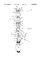
- FIG. 3 is an exploded view of the automatic shutoff valve of FIG. 2.
- FIG. 1 shows a tank truck, generally designated by the numeral 10, for transporting a flammable liquid, such as gasoline or oil, as it is parked next to an above-ground storage tank 12.
- the illustrated tank truck has a liquid pump 14 on its underside for pumping the tank truck's liquid contents from a first position corresponding to the height of the tank truck discharge, which is typically 18 inches to two feet off the ground, to second elevated position above the height of the storage tank 12.
- this second elevated position tank may be, in a typical situation, at a height of six feet or more above ground level.
- the liquid from the tank truck 10 is pumped to the second elevated position above the storage tank 12 through a dispensing line 16.
- This dispensing line is connected to the pump 14 through the agency of an internally threaded coupling 18 on the end of the dispensing line, which coupling is threadably received by an externally threaded outlet nipple of the pump 14.
- the dispensing line 16 has a first horizonal section 16a for transporting the tank truck contents to a location adjacent to the side of the storage tank 12, a first vertical section 16b for transporting the liquid to a height above the storage tank, a second horizonal section 16c for transporting the liquid over the storage tank 12, and a second vertical section 16d for directing the liquid downwardly into the storage tank's interior.
- the storage tank 12 has a first riser 20 formed by an upstanding boss that circumscribes a closable fill opening on its top side. This first riser 20 defines a fill aperture 22 adapted to receive the second vertical section 16d of the dispensing line 16. In the illustrated embodiment, the aperture 22 has a diameter of approximately 6 inches. As is well known in the art, the illustrated storage tank 12 also has a second riser 24 circumscribing a second closable opening for accommodating the entry of a vapor recovery line 26 for returning to the tank truck vapors displaced by the introduction of liquid into the storage tank 12, and a vent 28 for exhausting excess pressure from the storage tank 12.
- the second vertical section 16d of the dispensing line 16 includes an automatic shutoff valve assembly 30 for shutting off the pressurized flow of the liquid from the tank truck 10 whenever the level of liquid in the storage tank 12 reaches a predetermined level.
- This automatic shutoff valve assembly 30 is shown in substantially greater detail in FIGS. 2 and 3, from which it can be seen that the shutoff valve assembly 30 of the preferred embodiment includes a housing 31 having a lower section 32 with a generally cylindrical configuration and an upper section 33. The upper section 33 is disposed within a collar 34 (see FIG. 2) that fits within the fill aperture 22 (see FIG. 1) and seals the aperture against leakage of vapors.
- the central section of the particular valve assembly housing 31 illustrated has a diameter of approximately four inches and includes connector necks 36 and 38 of reduced diameter on its upper and lower axial ends. Each of these connector necks 36, 38 provides an axial opening to or from the internal space of the housing 31 and is internally threaded to threadably receive and interconnect with segments 16e and 16f of the second vertical dispensing line.
- the central portion of the housing 31 has a diameter of approximately 4 inches, with each of the illustrated dispensing line segments 16a-16f having a diameter of approximately two inches. When connected to the dispensing line segments, these connector necks 36 and 38 respectively define an inlet 40 and an outlet 42 for the housing.
- the housing 31 has an internal flow passage 44 that extends between the inlet and outlet. Fluid flow through this internal flow passage 44 is controlled by a valving assembly, generally designated by the numeral 48.
- the valving assembly 48 includes a shutoff valve 50 that, as will be explained in greater detail later, is used to terminate flow through the internal flow passage 44 of the housing 31 when the fluid level in the storage tank 12 reaches a predetermined level.
- the shutoff valve 50 takes the form of a poppet valve that moves axially within the housing 31.
- This poppet valve 50 has a horizontal section 50a that extends radially outwardly from a centrally disposed threaded opening 52 to an upwardly extending sidewall section of cylindrical configuration 50b.
- the upwardly extending sidewall section 50b of the shutoff valve 50 is concentrically positioned with respect to the generally cylindrical housing 31 sidewalls.
- the illustrated shutoff valve 50 is rigidly connected at its centrally disposed opening 52 to, and moved by, a valve stem 54.
- the connection between the shutoff valve 50 and the valve stem 54 is achieved by providing threads on the upper axial end of the valve stem 54, and threadably interconnecting that upper axial end to the centrally disposed opening 52 of the shutoff valve 50.
- a stem guide 56 controls movement of the valve stem 54, and thus insures that the poppet valve 50 moves in the direction of the axis of the housing 31.
- the stem guide 56 is centrally supported within the internal flow passage 44 by stem guide supports 58, which are rigidly attached to and extend radially inwardly into the center of the internal flow passage 44 from the internal sidewall of the housing 31.
- the shutoff valve 50 is movable from a first open or unseated position (illustrated in FIG. 2) in which the shutoff valve 50 permits fluid flow through the internal flow passage 44 of the housing 31 to a second closed or seated position in which fluid flow through the passage 44 is substantially blocked.
- the outer periphery of the lower surface of the horizonal section 50a of the shutoff valve 50 engages and seats against a valve seat 60.
- the valve seat 60 includes a circumferential support 60a that extends radially inwardly from the internal surface of the housing 31 to define a circular aperture 62 within the housing's internal flow passage 44.
- a raised contact surface 60b extends axially upwardly from the circumferential support about the aperture 62 to form a contact surface against which the lower surface of the shutoff valve 50 seats.
- the shutoff valve 50 is protected from the dynamic forces of pressurized flow impingement through the housing by a cup-shaped bonnet or shield 66.
- This bonnet 66 has a first generally horizontal section 66a that extends radially inwardly in a plane located proximal to the housing inlet 40.
- the horizonal section 66a of the bonnet is joined about its entire outer periphery by an axially downwardly extending sidewall section 66b.
- the bonnet 66 is concentrically disposed with respect to the shutoff valve 50 to form a controlled leak path between the shutoff valve 50 and the bonnet 66.
- This controlled leak path is accomplished in the illustrated embodiment by positioning the downwardly extending sidewall section 66b of the bonnet in closely spaced, parallel relationship to the upwardly extending sidewall section 50b of the shutoff valve.
- the bonnet 66 is supported by a bridge structure 68 consisting of two supports that extend between the internal sidewall of the housing 31 and the downwardly extending sidewall 66b of the bonnet.
- the valve stem 54 has an internal flow passage that extends between an inlet 70 in its upper axial end and a radially extending outlet 72 intermediate its ends.
- the radially extending outlet is disposed within a circumferential groove 74 in the valve stem guide 56.
- the circumferential groove 74 empties into a radial passageway 76 that flows outwardly through the housing 31 to the interior of the storage tank 12.
- the threaded upper axial end of the valve stem 54 also is threadably connected to a check ball retainer sleeve 78 which has a tubular configuration with an internally threaded lower portion. This lower portion of the check ball retainer sleeve 78 is screwed onto the upper axial of the valve stem 54 on top of the poppet valve 50.
- a check ball 80 is retained in the check ball retainer for selectively seating against the axial upper end of the valve stem 54 and blocking liquid flow into the valve stem's internal passageway.
- the check ball 80 is movable between a first open position, depicted in FIG. 2, in which liquid flow into the axial end of the valve stem 54 is permitted, to a second closed position, depicted in FIG.
- a compression spring 84 is disposed within the check ball retaining sleeve 78 to urge the check ball 80 to its first or open position.
- a retaining pin 86 extends across the upper opening of the check ball retaining sleeve 78 to maintain the check ball 80 within the retaining sleeve 78.
- the lower axial end of the valve stem 54 is attached to a yoke 88.
- the yoke 88 includes a pair of downwardly depending arms 88a that are joined at their upper axial ends by a cross piece 88b.
- the arms 88a support a first roller or cam follower 90 that is positioned between, and rotatably connected to, each of the two arms 88a by a first shaft 92.
- the first cam follower 90 rides upon and follows the profile of a first cam surface 91 of a cam 94 which is rigidly attached to a rotatable shaft 96.
- a second roller or cam follower 93 (see FIG.
- each of the yoke arms 88a has an open-ended elongated "U-shaped" groove 88c that is fitted about the rotatable shaft 96.
- these open-ended "U-shaped" grooves 88a allow the yoke 88 to be freely movable with respect to the rotatable shaft 96 in the vertical direction, while restricting relative movement between these two components 88 and 96 in all other directions.
- the shaft 96 of the cam 94 extends through opposite sides of the housing 31 sidewall and is rotatably supported by the housing 31.
- Crankshafts 98 are connected to the shaft 96 outside of the housing 31. These crankshafts 98 are pivotally joined to a tubular shaped float 100 by connecting links 102 (again, only one of which is illustrated).
- the crankshafts 98 and connecting links 102 together comprise actuating arms for rotating shaft 96.
- the float 100 is in concentrically disposed spaced relationship to, and slidably movable on, the lower segment 16f of the dispensing line.
- the shutoff valve 50 assembly In operation, when filling a storage tank 12, the shutoff valve 50 assembly is normally in the open position depicted in FIG. 2 during the initial filling operation, with the liquid level in the tank being below the float 100. In this position of the shutoff valve 50, pressurized liquid flow exits the dispensing line segment 16e and is introduced into the inlet 40 of the valve assembly housing 31. After impinging the bonnet 66, the liquid is deflected radially outwardly about the downwardly depending sidewall section 66b of the bonnet and most of the liquid passes into the opening between the shutoff valve 50 and the seat 60. The liquid passing through this opening then flows through the internal flow passage 44 of the housing 31, through the outlet 42, and into the dispensing line segment 16f.
- the volumetric flow capacity valve stem passage is greater than volumetric capacity of the controlled leakage space between the respective sidewall sections 50b, 66b of the shutoff valve and the bonnet.
- shutoff valve 50 initially maintains the shutoff valve 50 in a fully open position to maximize liquid flow through the valve assembly. Secondly, and perhaps even more importantly, it insures that the initial line of force between the cam surfaces 91, 97 and the cam followers 90, 93 passes through the axis of the crank 98. This avoids the possibility that lateral forces initially will be applied against the first cam follower 90 and cause it to override the first cam surface 91.
- first cam follower 90 rides upon and follows the first cam surface 91 which moves the yoke 88, valve stem 54 and shutoff valve 50 axially upward and the shutoff valve opens.
- first cam surface 91 and second cam surface 97 are opposing surfaces on a single cam 94.
- First cam surface 91 preferably is an external cam or disposed along the peripheral edge of the cam 94, while second cam surface 97 is an internal cam or disposed radially inward of the first cam surface 91.
- shutoff valve 50 advances toward the seated position depicted in FIG. 3.
- the shutoff valve 50 approaches its seated position, and the restriction between the shutoff valve 50 and the seat 66 becomes more severe, the resulting back pressure causes increased flow into the controlled leak path between the axially extending sidewalls 66b, 50b of the bonnet and shutoff valve. This increased flow exerts a corresponding increasing force against the check ball 80. Eventually this force increases to the level where it forces downward movement of the check ball 80 against the resilient force of the compression spring 84.
- the compression spring 84 is matched to the sizes of the valve assembly components and flow rates to effectuate closure of the check ball 80 immediately after the closure of the shutoff valve 50. Timing of the shutoff valve 50 and check ball 80 in this manner further facilitates the minimization of line shock from shutting off the flow of liquid in the dispensing line.
- the disclosed shutoff valve assembly protects the shutoff valve from dynamic flow pressure, operates effectively under conditions of pressurized dispensing line flow, and is highly effective in minimizing line shock that typically results from shutting off the flow of a pressured flow of liquid into a storage tank.
- the disclosed shutoff valve assembly advantageously controls the movement of the shutoff valve as a nonlinear function of the liquid level in the storage tank and provides a pressure assisted closure of the shutoff valve. It also minimizes the friction required to move the shutoff valve between open and closed positions and provides a valve assembly that resets to an open position when the liquid level in the storage tank falls below a predetermined level.
- the disclosed shutoff valve assembly also advantageously bleeds off any leakage at shutoff in the ullage above the liquid level in the storage tank, thus eliminating the possibility of siphoning of the liquid out of the tank.
Landscapes
- Engineering & Computer Science (AREA)
- Mechanical Engineering (AREA)
- General Engineering & Computer Science (AREA)
- Loading And Unloading Of Fuel Tanks Or Ships (AREA)
Abstract
Description
Claims (21)
Priority Applications (1)
| Application Number | Priority Date | Filing Date | Title |
|---|---|---|---|
| US08/486,813 US5850849A (en) | 1994-01-14 | 1995-06-07 | Storage tank shutoff valve with double cam assembly |
Applications Claiming Priority (2)
| Application Number | Priority Date | Filing Date | Title |
|---|---|---|---|
| US08/182,219 US5472012A (en) | 1994-01-14 | 1994-01-14 | Storage tank shutoff valve |
| US08/486,813 US5850849A (en) | 1994-01-14 | 1995-06-07 | Storage tank shutoff valve with double cam assembly |
Related Parent Applications (1)
| Application Number | Title | Priority Date | Filing Date |
|---|---|---|---|
| US08/182,219 Continuation-In-Part US5472012A (en) | 1994-01-14 | 1994-01-14 | Storage tank shutoff valve |
Publications (1)
| Publication Number | Publication Date |
|---|---|
| US5850849A true US5850849A (en) | 1998-12-22 |
Family
ID=46251468
Family Applications (1)
| Application Number | Title | Priority Date | Filing Date |
|---|---|---|---|
| US08/486,813 Expired - Lifetime US5850849A (en) | 1994-01-14 | 1995-06-07 | Storage tank shutoff valve with double cam assembly |
Country Status (1)
| Country | Link |
|---|---|
| US (1) | US5850849A (en) |
Cited By (23)
| Publication number | Priority date | Publication date | Assignee | Title |
|---|---|---|---|---|
| US6076546A (en) * | 1998-03-16 | 2000-06-20 | Waters; Michael | Overflow protection valve assembly |
| US6178994B1 (en) * | 2000-02-24 | 2001-01-30 | Young Do Industrial Co., Ltd. | Tap for compressed or liquefied gases having an overcharging prevention function |
| AU737490B2 (en) * | 1997-09-01 | 2001-08-23 | Scaniron Pty. Ltd. | Valves for use with LPG fuel systems |
| US6311723B1 (en) * | 1999-05-27 | 2001-11-06 | Multiflo Australia Pty Ltd. | Flow control valve assembly |
| US6415813B1 (en) * | 1999-10-22 | 2002-07-09 | Volkswagen Ag | Shut-off valve for a tank |
| US6539973B1 (en) * | 2002-01-14 | 2003-04-01 | George S. Cole & Associates, Incorporated | Water pressure-assisted flush valve |
| US20050199285A1 (en) * | 2004-01-20 | 2005-09-15 | William E.M. Jones | Liquid shut-off valve |
| US20080178944A1 (en) * | 2007-01-19 | 2008-07-31 | Flomeg, Llc | Flow control valve |
| ITPD20080235A1 (en) * | 2008-07-31 | 2010-02-01 | Cavagna Group Switzerland S A | VALVE DEVICE FOR FILLING CONTAINERS, IN PARTICULAR TANKS INTENDED TO CONTAIN LIQUEFIED GAS |
| US20100051134A1 (en) * | 2006-11-24 | 2010-03-04 | Serge Albert Pierre Selles | Fuel storage facility and method for filling and/or emptying the tanks of said facility |
| US20100307608A1 (en) * | 2002-10-31 | 2010-12-09 | Weir Minerals Australia Ltd. | Valve assembly |
| US20110108159A1 (en) * | 2009-11-10 | 2011-05-12 | Delaware Capital Formation, Inc. | Vapor valve for storage tank |
| US20130256062A1 (en) * | 2012-03-27 | 2013-10-03 | Lincoln Industrial Corporation | Lubricant reservoir refilling system with shut-off |
| US8844679B2 (en) | 2010-11-29 | 2014-09-30 | Lincoln Industrial Corporation | Pump having venting and non-venting piston return |
| US9086186B2 (en) | 2011-10-14 | 2015-07-21 | Lincoln Industrial Corporation | System having removable lubricant reservoir and lubricant refilling station |
| US9140246B2 (en) | 2012-03-19 | 2015-09-22 | Lincoln Industrial Corporation | Lance pump having vertically mounted stepper motor |
| US9175805B2 (en) | 2011-09-29 | 2015-11-03 | Lincoln Industrial Corporation | Lubricant filtration system |
| US9239044B2 (en) | 2012-03-19 | 2016-01-19 | Lincoln Industrial Corporation | Lance pump having horizontally mounted stepper/servo motor |
| US9341173B2 (en) | 2011-12-20 | 2016-05-17 | Lincoln Industrial Corporation | Lance pump with a ram |
| US9463971B2 (en) | 2012-02-21 | 2016-10-11 | Opw Fueling Containment Systems, Inc. | Testable overfill prevention valve |
| US9671065B2 (en) | 2013-10-17 | 2017-06-06 | Lincoln Industrial Corporation | Pump having wear and wear rate detection |
| US10371283B2 (en) | 2014-01-03 | 2019-08-06 | Franklin Fueling Systems, Llc | Overfill prevention valve with remote testing |
| US11365826B2 (en) | 2012-09-14 | 2022-06-21 | Franklin Fueling Systems, Llc | Overfill prevention valve |
Citations (33)
| Publication number | Priority date | Publication date | Assignee | Title |
|---|---|---|---|---|
| US539204A (en) * | 1895-05-14 | Valve-operating mechanism | ||
| US617597A (en) * | 1899-01-10 | Ball-cock | ||
| US782331A (en) * | 1904-12-10 | 1905-02-14 | Peter Fraser | Steam-trap. |
| US1041824A (en) * | 1911-01-23 | 1912-10-22 | William Loser | Ball-valve for flushing-tanks. |
| US1114019A (en) * | 1911-09-09 | 1914-10-20 | Sf Bowser & Co Inc | Automatic valve. |
| FR486020A (en) * | 1916-08-11 | 1918-03-05 | Westinghouse Electric Corp | Improvements relating to electric knife switches |
| US1681439A (en) * | 1926-02-06 | 1928-08-21 | Frick Co | Fluid-regulating valve |
| US1762306A (en) * | 1927-11-26 | 1930-06-10 | Mueller Co | Ball cock |
| DE613275C (en) * | 1933-09-29 | 1935-05-15 | Berluto Armaturen Akt Ges | Closed float valve with rolling lever |
| US2504638A (en) * | 1944-12-02 | 1950-04-18 | Browning Lab Inc | Tank filling means |
| DE1142736B (en) * | 1960-09-19 | 1963-01-24 | F W Oventrop Arn Sohn K G | Float-operated overfill protection, especially for heating oil containers |
| US3756269A (en) * | 1971-11-19 | 1973-09-04 | H Brown | Maximum liquid level control valve |
| US3770028A (en) * | 1972-01-26 | 1973-11-06 | M Madden | Anti-polluting filling and vapor recovery system |
| US3776283A (en) * | 1972-06-15 | 1973-12-04 | Gulf Research Development Co | Vapor recovery system |
| US4058148A (en) * | 1976-03-18 | 1977-11-15 | Exxon Research & Engineering Co. | Vapor hose hookup assurance |
| US4064907A (en) * | 1976-09-30 | 1977-12-27 | Rego | Fill limiting filler valve unit |
| US4142552A (en) * | 1977-03-17 | 1979-03-06 | Harley D. Brown | Maximum liquid level control valve |
| US4483367A (en) * | 1984-01-20 | 1984-11-20 | Rochester Gauges, Inc. | Stop fill valve |
| US4541464A (en) * | 1982-10-15 | 1985-09-17 | Kosan Teknova A/S | Valve device for the prevention of the overfilling of gas cylinders and similar portable containers |
| US4986320A (en) * | 1987-10-13 | 1991-01-22 | Kesterman James E | Drop tube having an overfill valve |
| USRE33555E (en) * | 1984-05-10 | 1991-03-19 | Tank overfill valve | |
| US5010915A (en) * | 1990-06-06 | 1991-04-30 | Ebw, Inc. | Two stage automatic shut off valve |
| US5027870A (en) * | 1990-05-01 | 1991-07-02 | Emco Wheaton, Inc. | Overfill prevention mechanism for storage tanks |
| US5033519A (en) * | 1990-06-06 | 1991-07-23 | Ebw, Inc. | Storage tank flow control valve |
| US5095937A (en) * | 1990-06-06 | 1992-03-17 | Ebw, Inc. | Two stage automatic shut off valve |
| US5141019A (en) * | 1990-06-06 | 1992-08-25 | Ebw, Inc. | Two stage automatic shutoff valve |
| US5152315A (en) * | 1989-12-15 | 1992-10-06 | Lafon Production S.A. | Overfill device for a liquid storage tank |
| US5163470A (en) * | 1989-12-29 | 1992-11-17 | Showa Kiki Kogyo Co., Ltd. | Overfill preventing device in underground liquid storage tank |
| US5179984A (en) * | 1985-06-17 | 1993-01-19 | Sharp Bruce R | Storage tank system having an internal overfill means |
| US5187979A (en) * | 1991-04-26 | 1993-02-23 | Edmark Iii Karl W | Multi-sensor probe assembly and method for fuel storage system including overflow protection means |
| US5207241A (en) * | 1992-08-07 | 1993-05-04 | Babb Matthew T | Liquid shut-off valve |
| US5235999A (en) * | 1991-11-26 | 1993-08-17 | Guillotine, Inc. | Drop tube assembly with shut-off valve and method for assembling the same |
| US5472012A (en) * | 1994-01-14 | 1995-12-05 | Dover Corporation | Storage tank shutoff valve |
-
1995
- 1995-06-07 US US08/486,813 patent/US5850849A/en not_active Expired - Lifetime
Patent Citations (33)
| Publication number | Priority date | Publication date | Assignee | Title |
|---|---|---|---|---|
| US539204A (en) * | 1895-05-14 | Valve-operating mechanism | ||
| US617597A (en) * | 1899-01-10 | Ball-cock | ||
| US782331A (en) * | 1904-12-10 | 1905-02-14 | Peter Fraser | Steam-trap. |
| US1041824A (en) * | 1911-01-23 | 1912-10-22 | William Loser | Ball-valve for flushing-tanks. |
| US1114019A (en) * | 1911-09-09 | 1914-10-20 | Sf Bowser & Co Inc | Automatic valve. |
| FR486020A (en) * | 1916-08-11 | 1918-03-05 | Westinghouse Electric Corp | Improvements relating to electric knife switches |
| US1681439A (en) * | 1926-02-06 | 1928-08-21 | Frick Co | Fluid-regulating valve |
| US1762306A (en) * | 1927-11-26 | 1930-06-10 | Mueller Co | Ball cock |
| DE613275C (en) * | 1933-09-29 | 1935-05-15 | Berluto Armaturen Akt Ges | Closed float valve with rolling lever |
| US2504638A (en) * | 1944-12-02 | 1950-04-18 | Browning Lab Inc | Tank filling means |
| DE1142736B (en) * | 1960-09-19 | 1963-01-24 | F W Oventrop Arn Sohn K G | Float-operated overfill protection, especially for heating oil containers |
| US3756269A (en) * | 1971-11-19 | 1973-09-04 | H Brown | Maximum liquid level control valve |
| US3770028A (en) * | 1972-01-26 | 1973-11-06 | M Madden | Anti-polluting filling and vapor recovery system |
| US3776283A (en) * | 1972-06-15 | 1973-12-04 | Gulf Research Development Co | Vapor recovery system |
| US4058148A (en) * | 1976-03-18 | 1977-11-15 | Exxon Research & Engineering Co. | Vapor hose hookup assurance |
| US4064907A (en) * | 1976-09-30 | 1977-12-27 | Rego | Fill limiting filler valve unit |
| US4142552A (en) * | 1977-03-17 | 1979-03-06 | Harley D. Brown | Maximum liquid level control valve |
| US4541464A (en) * | 1982-10-15 | 1985-09-17 | Kosan Teknova A/S | Valve device for the prevention of the overfilling of gas cylinders and similar portable containers |
| US4483367A (en) * | 1984-01-20 | 1984-11-20 | Rochester Gauges, Inc. | Stop fill valve |
| USRE33555E (en) * | 1984-05-10 | 1991-03-19 | Tank overfill valve | |
| US5179984A (en) * | 1985-06-17 | 1993-01-19 | Sharp Bruce R | Storage tank system having an internal overfill means |
| US4986320A (en) * | 1987-10-13 | 1991-01-22 | Kesterman James E | Drop tube having an overfill valve |
| US5152315A (en) * | 1989-12-15 | 1992-10-06 | Lafon Production S.A. | Overfill device for a liquid storage tank |
| US5163470A (en) * | 1989-12-29 | 1992-11-17 | Showa Kiki Kogyo Co., Ltd. | Overfill preventing device in underground liquid storage tank |
| US5027870A (en) * | 1990-05-01 | 1991-07-02 | Emco Wheaton, Inc. | Overfill prevention mechanism for storage tanks |
| US5141019A (en) * | 1990-06-06 | 1992-08-25 | Ebw, Inc. | Two stage automatic shutoff valve |
| US5095937A (en) * | 1990-06-06 | 1992-03-17 | Ebw, Inc. | Two stage automatic shut off valve |
| US5033519A (en) * | 1990-06-06 | 1991-07-23 | Ebw, Inc. | Storage tank flow control valve |
| US5010915A (en) * | 1990-06-06 | 1991-04-30 | Ebw, Inc. | Two stage automatic shut off valve |
| US5187979A (en) * | 1991-04-26 | 1993-02-23 | Edmark Iii Karl W | Multi-sensor probe assembly and method for fuel storage system including overflow protection means |
| US5235999A (en) * | 1991-11-26 | 1993-08-17 | Guillotine, Inc. | Drop tube assembly with shut-off valve and method for assembling the same |
| US5207241A (en) * | 1992-08-07 | 1993-05-04 | Babb Matthew T | Liquid shut-off valve |
| US5472012A (en) * | 1994-01-14 | 1995-12-05 | Dover Corporation | Storage tank shutoff valve |
Cited By (41)
| Publication number | Priority date | Publication date | Assignee | Title |
|---|---|---|---|---|
| AU737490B2 (en) * | 1997-09-01 | 2001-08-23 | Scaniron Pty. Ltd. | Valves for use with LPG fuel systems |
| US6076546A (en) * | 1998-03-16 | 2000-06-20 | Waters; Michael | Overflow protection valve assembly |
| US6311723B1 (en) * | 1999-05-27 | 2001-11-06 | Multiflo Australia Pty Ltd. | Flow control valve assembly |
| US6415813B1 (en) * | 1999-10-22 | 2002-07-09 | Volkswagen Ag | Shut-off valve for a tank |
| US6178994B1 (en) * | 2000-02-24 | 2001-01-30 | Young Do Industrial Co., Ltd. | Tap for compressed or liquefied gases having an overcharging prevention function |
| US6539973B1 (en) * | 2002-01-14 | 2003-04-01 | George S. Cole & Associates, Incorporated | Water pressure-assisted flush valve |
| US20100307608A1 (en) * | 2002-10-31 | 2010-12-09 | Weir Minerals Australia Ltd. | Valve assembly |
| US9322486B2 (en) | 2002-10-31 | 2016-04-26 | Weir Minerals Australia Ltd. | Valve assembly |
| US8402994B2 (en) | 2002-10-31 | 2013-03-26 | Weir Minerals Australia Ltd. | Valve assembly |
| US8025076B2 (en) | 2002-10-31 | 2011-09-27 | Weir Minerals Australia Ltd | Valve assembly |
| US7392820B2 (en) * | 2004-01-20 | 2008-07-01 | William E. M. Jones | Liquid shut-off valve |
| US20050199285A1 (en) * | 2004-01-20 | 2005-09-15 | William E.M. Jones | Liquid shut-off valve |
| US20100051134A1 (en) * | 2006-11-24 | 2010-03-04 | Serge Albert Pierre Selles | Fuel storage facility and method for filling and/or emptying the tanks of said facility |
| US8256471B2 (en) * | 2006-11-24 | 2012-09-04 | Ifp | Fuel storage facility and method for filling and/or emptying the tanks of said facility |
| US20080178944A1 (en) * | 2007-01-19 | 2008-07-31 | Flomeg, Llc | Flow control valve |
| US7891373B2 (en) | 2007-01-19 | 2011-02-22 | Flomeg, Llc | Flow control valve |
| US20100024918A1 (en) * | 2008-07-31 | 2010-02-04 | Cavagna Group Switzerland S.A. | Valve device for filling containers, in particular containers intended to contain liquefied gases |
| US8256451B2 (en) | 2008-07-31 | 2012-09-04 | Cavagna Group Switzerland S.A. | Valve device for filling containers, in particular containers intended to contain liquefied gases |
| EP2154418A3 (en) * | 2008-07-31 | 2017-07-12 | Cavagna Group S.p.A. | Valve device for filling containers, in particular containers intended to contain liquefied gases |
| ITPD20080235A1 (en) * | 2008-07-31 | 2010-02-01 | Cavagna Group Switzerland S A | VALVE DEVICE FOR FILLING CONTAINERS, IN PARTICULAR TANKS INTENDED TO CONTAIN LIQUEFIED GAS |
| US20110108159A1 (en) * | 2009-11-10 | 2011-05-12 | Delaware Capital Formation, Inc. | Vapor valve for storage tank |
| US9022177B2 (en) | 2010-11-29 | 2015-05-05 | Lincoln Industrial Corporation | Pump having stepper motor and overdrive control |
| US8936135B2 (en) | 2010-11-29 | 2015-01-20 | Lincoln Industrial Corporation | Pump having heated reservoir |
| US8844679B2 (en) | 2010-11-29 | 2014-09-30 | Lincoln Industrial Corporation | Pump having venting and non-venting piston return |
| US10851940B2 (en) | 2010-11-29 | 2020-12-01 | Lincoln Industrial Corporation | Pump having diagnostic system |
| US9140407B2 (en) | 2010-11-29 | 2015-09-22 | Lincoln Industrial Corporation | Pump having stirrer and direct feed |
| US9212779B2 (en) | 2010-11-29 | 2015-12-15 | Lincoln Industrial Corporation | Pump having diagnostic system |
| US9175805B2 (en) | 2011-09-29 | 2015-11-03 | Lincoln Industrial Corporation | Lubricant filtration system |
| US9086186B2 (en) | 2011-10-14 | 2015-07-21 | Lincoln Industrial Corporation | System having removable lubricant reservoir and lubricant refilling station |
| US9341173B2 (en) | 2011-12-20 | 2016-05-17 | Lincoln Industrial Corporation | Lance pump with a ram |
| US9463971B2 (en) | 2012-02-21 | 2016-10-11 | Opw Fueling Containment Systems, Inc. | Testable overfill prevention valve |
| EP3124431A1 (en) | 2012-02-21 | 2017-02-01 | OPW Fueling Containment Systems, Inc. | Testable overfill prevention valve |
| US11061418B2 (en) | 2012-02-21 | 2021-07-13 | Opw Fueling Components, Llc | Testable overfill prevention valve |
| US9239044B2 (en) | 2012-03-19 | 2016-01-19 | Lincoln Industrial Corporation | Lance pump having horizontally mounted stepper/servo motor |
| US9140246B2 (en) | 2012-03-19 | 2015-09-22 | Lincoln Industrial Corporation | Lance pump having vertically mounted stepper motor |
| WO2013148233A1 (en) * | 2012-03-27 | 2013-10-03 | Lincoln Industrial Corporation | Lubricant reservoir refilling system with shut-off |
| US20130256062A1 (en) * | 2012-03-27 | 2013-10-03 | Lincoln Industrial Corporation | Lubricant reservoir refilling system with shut-off |
| US11365826B2 (en) | 2012-09-14 | 2022-06-21 | Franklin Fueling Systems, Llc | Overfill prevention valve |
| US9671065B2 (en) | 2013-10-17 | 2017-06-06 | Lincoln Industrial Corporation | Pump having wear and wear rate detection |
| US10371283B2 (en) | 2014-01-03 | 2019-08-06 | Franklin Fueling Systems, Llc | Overfill prevention valve with remote testing |
| US11578813B2 (en) | 2014-01-03 | 2023-02-14 | Franklin Fueling Systems, Llc | Overfill prevention valve with remote testing |
Similar Documents
| Publication | Publication Date | Title |
|---|---|---|
| US5850849A (en) | Storage tank shutoff valve with double cam assembly | |
| US5472012A (en) | Storage tank shutoff valve | |
| US4213488A (en) | Valve means responsive to the operation of a vapor-seal valve for preventing fuel spillage from the discharge spout of a vapor-recovery fuel dispensing nozzle | |
| US5950688A (en) | Apparatus and method for preventing fuel spillage | |
| AU2002360778C1 (en) | Non tank pressurizing fast fill receiver and system for vehicles | |
| EP0888236B1 (en) | Vapor recovery system accommodating orvr vehicles | |
| US5535984A (en) | Safety coupler locking means | |
| US8171965B2 (en) | Fuel leak prevention system | |
| US4157104A (en) | Gasoline dispensing and vapor recovery apparatus | |
| CA2034755C (en) | Two stage automatic shut off valve | |
| US3563263A (en) | System for storing petroleum products | |
| US5832953A (en) | Overfill shut-off system for liquid storage tanks | |
| US5531247A (en) | Temperature and pressure resistant shutoff valve | |
| WO1998051610A1 (en) | Overfill protection for fuel tanks | |
| US5388622A (en) | Automatic shutoff valve | |
| CA2233032C (en) | Above-ground tank auto-limiter | |
| US5655565A (en) | Above-ground tank auto-limiter | |
| US6523564B1 (en) | Above ground overfill valve | |
| US5398722A (en) | Automatic control valve and method | |
| US6499518B2 (en) | Nonoverflow, magnetic float valve assembly | |
| US4469117A (en) | Valve device for the prevention of the overfilling of portable containers, particularly gas cylinders | |
| AU2007229427B2 (en) | Non tank pressurizing fast fill receiver and system for vehicles | |
| GB2275677A (en) | Overpressure prevention device for storage tanks | |
| EP0820959A1 (en) | Valve for a recovery system | |
| US20220227223A1 (en) | Fully-integrated, fluid flow-control module designed for installation within an iso filler neck of a top-fill def tank |
Legal Events
| Date | Code | Title | Description |
|---|---|---|---|
| AS | Assignment |
Owner name: DOVER CORPORATION, NEW YORK Free format text: ASSIGNMENT OF ASSIGNORS INTEREST;ASSIGNOR:WOOD, CHESTER;REEL/FRAME:007602/0397 Effective date: 19950802 |
|
| STCF | Information on status: patent grant |
Free format text: PATENTED CASE |
|
| AS | Assignment |
Owner name: DELAWARE CAPITOL FORMATION, INC., A CORP. OF DELAW Free format text: ASSIGNMENT OF ASSIGNORS INTEREST;ASSIGNOR:DOVER CORPORATION, A CORP. OF DELAWARE;REEL/FRAME:010444/0858 Effective date: 19991222 |
|
| FPAY | Fee payment |
Year of fee payment: 4 |
|
| REMI | Maintenance fee reminder mailed | ||
| FPAY | Fee payment |
Year of fee payment: 8 |
|
| FPAY | Fee payment |
Year of fee payment: 12 |
|
| AS | Assignment |
Owner name: CLOVE PARK INSURANCE COMPANY, NEW YORK Free format text: ASSIGNMENT OF ASSIGNORS INTEREST;ASSIGNOR:DELAWARE CAPITAL FORMATION, INC.;REEL/FRAME:030820/0499 Effective date: 20130630 Owner name: CP FORMATION LLC, NEW YORK Free format text: ASSIGNMENT OF ASSIGNORS INTEREST;ASSIGNOR:CLOVE PARK INSURANCE COMPANY;REEL/FRAME:030820/0462 Effective date: 20130630 Owner name: CLOVE PARK INSURANCE COMPANY, NEW YORK Free format text: ASSIGNMENT OF ASSIGNORS INTEREST;ASSIGNOR:DELAWARE CAPITAL FORMATION, INC.;REEL/FRAME:030820/0476 Effective date: 20130630 Owner name: OPW FUELING COMPONENTS INC., OHIO Free format text: ASSIGNMENT OF ASSIGNORS INTEREST;ASSIGNOR:CP FORMATION LLC;REEL/FRAME:030820/0448 Effective date: 20130701 |