FIELD OF THE INVENTION
The present invention relates generally to a drum type washing machine with balancing devices provided to a spin basket which rotates about a horizontal axis.
BACKGROUND OF THE INVENTION
A conventional drum type washing machine, which performs a washing/hydro-extracting (spin-drying) task with the rotation of its spin basket, has balancers that prevent the spin basket from producing abnormal vibrations due to laundry not being evenly arranged therein. There are two types of balancing devices: a counterweight balancer that reduces the vibration by means of a counterweight having a predetermined weight, and a liquid balancer which is provided on a washing machine's spin basket in order to oppose an imbalance of laundry and restrain the generation of vibration.
FIG. 7 schematically illustrates a conventional drum type washing machine with counterweights.
The drum washing machine includes a housing 1, a tub 2 held by suspension arms in the housing 1, and a spin basket 3 rotatably provided in the tub 2. An electric motor 8, installed below the tub 3, rotates the tub 3 about a shaft (not illustrated) horizontally installed, thereby performing a washing/hydro-extracting task. Counterweights 4a and 4b, each of predetermined weight, are attached to the tub 2 to prevent the production of vibration during the washing/hydro-extracting operation. The counterweight 4a attached to the front of the tub 2 is 11.4 kg, and the counterweight 4b provided to the top of the tub 2 is 12.2 kg. These counterweights 4a and 4b are made from cast iron and are joined to the tub 2 by bolts 4c.
The above-described conventional drum type washing machine has the following disadvantages:
First, the conventional balancer using the counterweights only lowers the amplitude of vibrations generated during operation rather than eliminating them entirely. Second, since these counterweights are quiet heavy, it is difficult to install them on the tub and the overall weight of the washing machine is increased, resulting in difficult construction and transport. Third, the bolts which fasten the counterweights to the tub, over long periods of use, loosen due to corrosion or fatigue, resulting in noise, and, in the worst case, the possibility of damage to the balancer and the washing machine as well.
To solve the aforementioned problems, a liquid balancer directly installed in a washing machine's spin basket was proposed in EP Publication No. EP 0 390 343 A2.
FIG. 8 depicts a conventional drum washing machine employing such a liquid balancer.
The drum washing machine of FIG. 8 includes a housing 1, a tub 2 held by suspension arms in the housing 1, an spin basket 3 rotatably installed within the tub 2, and an electric motor 8 installed below the tub 2 to rotate the spin basket 3. The tub 2 serves as a water tub, and the spin basket 3 is disposed within the tub 2 parallel to the ground rather than upright. One end 5a of a horizontally-supported shaft 5 is joined to the back of the spin basket 3. The other end 5b of the shaft 5 extends to the outside of the tub 2, and is connected to the motor 8 through a drive belt 6 so that the motor 8 can rotate the spin basket 3.
The washing operation of such a drum washing machine is carried out by suds created by the rotation of the spin basket 3. After the washing and rinsing of the clothes, excess water is removed from the clothes by centrifugal force created by the spin basket 3 turning at high speeds during the hydro-extracting process so that they contain only enough moisture for ironing.
A balancer is provided to the front of the spin basket 3 so as to prevent vibration from being produced during the high-speed rotation. The balancer is realized as an annular passageway 7 and a liquid, commonly a saline solution, of given quantity contained therein.
The center of gravity S-S' of the basket 3 is offset from the geometric center O-O' of the spin basket 3 due to the laundry being gathered on one spot in the spin basket 3. The liquid housed in the passageway 7 is moved to oppose an imbalance resulting from of the centrifugal force caused by that offset relationship.
In such a conventional drum washing machine, however, the liquid used to counteract the imbalance and decrease the vibration amplitude of the spin basket cannot eliminate the vibration completely. Consequently, the spin basket rotates eccentric relative to the center of gravity thereby creating abnormal vibrations, causing the washing machine's components such as bearings to wear out prematurely and the deterioration of the durability of the washing machine.
Additionally, when the magnitude of the spin basket's unbalance exceeds the critical point of counterbalance, the liquid balancer is incapable of dynamically balancing the spin basket. In order to compensate for such an imbalance sufficiently, the liquid balancer must be of great bulk. However, it is not easy to install such a heavy liquid balancer on the washing machine.
SUMMARY OF THE INVENTION
The present invention is a drum washing machine with improved balancing devices that can satisfy the aforementioned need.
It is an objective of the present invention to provide a drum type washing machine that can eliminate the vibration of its spin basket and prevent the spin basket's axis of rotation from deviating from its center of gravity.
It is another objective of the present invention to provide a drum type washing machine with balancing devices which can more effectively counteract an imbalance in its spin basket.
In order to obtain the aforementioned objectives of the present invention, the inventive drum type washing machine includes: a housing, a tub suspended horizontally within the housing, a spin basket rotatably mounted horizontally inside the tub, a motor rotating the spin basket, and balancing devices having radially spaced annular chambers provided to at least one of the two sides of the spin basket and a plurality of balls freely movable within the respective chambers which dynamically counterbalance imbalances produced during the rotation of the spin basket.
The chambers are concentrically formed and contain a given amount of liquid with a prescribed viscosity. The diameter of the balls in the inner chamber is smaller than that of the balls in the outer chamber, and the outer chamber's corners are less tightly curved than the inner chamber's corners. The chambers are formed by connecting the spin basket's side panel, which has a first annular groove formed therein, with a plate member, which has a second groove corresponding to the first groove. The plate member is joined to the side panel by the use of either bolts or rivets. The first and second grooves are designed to be substantially different from each other in axial depth, and the depth of one of the grooves is larger than the radius of the respective balls.
The chambers are respectively provided to both sides of the spin basket, and each chamber is connected to the outer circumference of the spin basket by bolts attached to the spin basket's outer surface. A third groove may be formed on a portion of the side panel of the spin basket corresponding to the first groove so as to accommodate the first groove of the first plate member.
BRIEF DESCRIPTION OF THE ATTACHED DRAWINGS
In the drawings:
FIG. 1 is a side-sectional view of a drum type washing machine with balancing devices using balls in accordance with the present invention;
FIGS. 2A and 2B are exploded and assembled views, respectively, depicting a chamber coupling structure in accordance with the first preferred embodiment of the present invention;
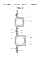
FIG. 3 depicts a chamber coupling structure in accordance with the second preferred embodiment of the present invention;
FIG. 4 depicts a chamber coupling structure in accordance with the third preferred embodiment of the present invention;
FIG. 5 depicts a chamber coupling structure in accordance with the fourth preferred embodiment of the present invention;
FIG. 6 depicts chambers each formed with a predetermined depth and having curved corners in accordance with the present invention;
FIG. 7 schematically illustrates a front perspective view of a convention drum type washing machine with counterweights for counteracting an imbalance in a spin basket; and
FIG. 8 depicts a vertical sectional view of a conventional drum type washing machine employing a liquid balancer.
DETAILED DESCRIPTION OF PREFERRED EMBODIMENTS
Reference will now be made in detail to the preferred embodiments of the present invention, examples of which are illustrated in the accompanying drawings.
FIG. 1 is a side-sectional view of a drum washing machine with a balancing device using balls in accordance with the present invention.
The drum washing machine of FIG. 1 includes a housing 10, a tub 20 held in the housing 10, a spin basket 30 rotatably installed within the tub 20, and an electric motor 40, which rotates the spin basket 30, installed below the tub 20. The housing 10 is a quadrangular case, and the spin basket 20 is cylindrical in shape and horizontally held by four buffer springs 12 arranged at four locations in the housing 10. The spin basket 30, also of cylindrical shape, is horizontally disposed within the tub 20. Each of the buffer springs 12 has an upper end connected to the housing 10 and a lower end connected to the top of the tub 20. A pair of shock absorbers 13 are installed between the lower part of the tub 20 and the housing 10.
Openings 11, 21 and 32a are formed respectively on: the front of the housing 10, a predetermined spot of the tub 20 corresponding to that of the housing 10, and a corresponding spot of the spin basket 30. A door (not illustrated) is disposed on the front of the housing 10 that opens and closes the entrance to the tub 20 and the spin basket 30. The spin basket 30 consists of a cylindrically-shaped body 31, and side panels 32 and 33 each constituting the front and back of the body 31. A plurality of holes 31a are uniformly distributed in the body 31 so that water can flow freely between the spin basket 30 and the tub 20. A plurality of lifters 31b are provided to the body 31 and designed to protrude inward in the form of a "V", spaced 60° from each other. These lifters 31b raise and drop laundry during washing. A horizontally-supported shaft 41 has one end 41a connected to the side panel 33 that forms the back of the spin basket 30, and the other end 41b extending to the rear of the tub 20 and connected to a first pulley 42. A belt 44 is provided between the first pulley 42 and a second pulley 43 that is connected to the motor shaft 40a so that the rotating force of the motor 40 is transmitted to the spin basket 30.
As described above, the shaft 41 is horizontally supported by a pair of bearings 46a and 46b placed in a bearing housing 45. A supporting member 47 has an outer end diverged in three directions and extends to the side panel 33's edge to be joined to the side panel 33 of the spin basket 30 so that the one end 41a of the shaft 41 is connected to the center of the supporting member 47.
The spin basket 30 includes a pair of balancing devices 50 provided to respective side panels 32 and 33 so as to remove the vibration and imbalance created during rotation. The balancing devices 50 are oppositely disposed respectively to each other thereby offsetting movement created during rotation and enhancing the balancing characteristics. Each of balancing devices 50 comprises annular chambers 51a and 51b that are formed on radially inner and outer parts of each of the side panels 32 and 33, and spherically balls 52a and 52b that are seated in the chambers 51a and 51b, respectively. The balls move along the corresponding chambers to oppose an imbalance in the spin basket 30. A secondary plate member 53 closes the chambers 51a, 51b (as will be described in more detail subsequently). The plate members in FIG. 1 are secured to respective side panels 32, 33 by means of bolts 60 which extend completely through the spin basket. Each bolt includes a head 62 at one end, and a coupling nut 61 is threaded to the other end of each bolt 60.
The chambers 51a and 51b contain a liquid of a predetermined viscosity, such as an oil, in order to facilitate the movement of the balls 52a and 52b and to enhance the balancing characteristics. In other words, when there is an imbalance in the spin basket 30, the balls 52a and 52b and the liquid relocate to a predetermined position to oppose the imbalance. If the magnitude of the imbalance does not exceed a predetermined critical point of counterbalance of the balancing devices, the balls 52a and 52b move close to each other to make the vibration amplitude zero so the liquid does not flow.
If the magnitude of the imbalance still exceeds the critical point of counterbalance, after the balls have moved into their counterbalancing position, the liquid is then also moved to oppose the imbalance, thereby countering the unbalanced state of the basket 30.
Each of the balancing devices 50 includes at least one chamber and a plurality of the balls seated therein. The inner and outer chambers 51a and 51b are concentric to the axis of rotation and radially spaced from each other by a predetermined distance. They are sealed by means to be subsequently described. The balls 52a in the inner chambers 51a are designed to be smaller than the balls 52b in the outer chambers 51b so that there is a difference between the balancing effects of the inner and outer chambers 51a and 51b to thereby ensuring a more delicate counterbalancing action.
The balancing effect is in proportion to the centrifugal force (F=MRW2), and the control effect of the radially inner balancing device is designed to be smaller than that of the outer one by reducing the mass of the balls 52a seated in the inner chambers 51a so that the overall control technique is more sophisticated.
The coupling structure of the chambers 51a and 51b will be more fully described as follows.
As described above, the balancing devices 50 provided to the both side panels 32 and 33 are formed symmetrically, and the structure of the chambers 51a and 51b on the side panel 32 will be described by way of example. The inner chambers 51a and the outer chambers 51b of different size have essentially the same construction, and the inner chambers 51a are now described as an example.
FIGS. 2A and 2B are enlarged views of an alternative coupling structure of the chambers 51a and 51b.
Each of the chambers 51a, 51b is formed by the combination of a first groove 32b formed axially inward on the side panel 32 of the spin basket 30 and a second groove 53a formed in axial alignment with to the first groove 32b. More specifically, the second groove 53a is formed on a secondary plate member 53, and the plate member 53 is joined to the side panel 32 of the spin basket 30 by the use of small bolts 70. Nuts 72 are then screw onto the bolts whose bolt heads 71 are axially facing the inside of the spin basket 30. The panel 32 (and also 33) includes three bent portions 32c arranged to straddle both of the chambers 51a, 51b. Those bent portions form projections which oppose respective recesses formed by bent portions 53b of the plate member 53. Packing material 90 is inserted between the bent portions 32c and 53b and compressed to form a seal so as to eliminate leakage of the oil from the chambers 51a, 51b.
FIG. 3 depicts a chamber coupling structure in accordance with a second preferred embodiment of the present invention.
In this embodiment, the plate member 53 is joined to the side panel 32 of the spin basket 30 by the use of rivets 80. The rivets 80 are pressed from the outside of the spin basket 30 to fasten the panel 32 and side panel 32 together.
FIG. 4 depicts a chamber coupling structure in accordance with a third preferred embodiment of the present invention.
In this embodiment, the plate member 53 is joined to the side panel 32 of the spin basket 30 by welding.
FIG. 5 depicts a chamber coupling structure in accordance with a fourth preferred embodiment of the present invention.
A radially inner 151a is formed by the combination of a first plate member 54 with a first annular groove 54a formed inward thereon and a second plate member 55 with a second annular groove 55a formed outward thereon corresponding in location to the first groove 54a. A radially outer chamber 151b is also formed by the plate members 54, 55. The first plate member 54 is connected to the second plate member 55 by welding, and a bolt 60 disposed closely to the outer surface of a lifter 31b is used to fasten the members 54 and 55 to the side panel 32. The bolt 60 is similar to that disclosed earlier in connection with FIG. 1.
Accordingly, the parts where the members 54 and 55 are joined together by welding are not exposed to the inside of the spin basket 30, thereby eliminating corrosion and oxidization on those joints, and making the inside of the spin basket 30 smooth. The bolt 60 extends along the outer surface of the lifter 31b, and its bolt head 62 (see FIG. 1) abuts against the outside of the balancing device 50 located at the axial rear. A nut 61 screws onto the bolt 60 in front of the axial other balancing device 50 placed on the front so that the front and rear balancing devices 50 are joined together, with the spin basket 30 disposed therebetween. The bolt 60 is situated radially between the radially inner chamber 151a and the radially outer chamber 151b.
To create the inner chamber 115a, a third groove 32d is formed on a portion of the side panel 32 corresponding in location to the first groove 54a of the first plate member 54 in order to accommodate the first groove 54a, and the combination of the first and second plate members 54 and 55 is designed to lie flush with the side panel 32.
Referring now to FIG. 6, another chamber structure is fully described as follows.
The contact points (i.e., the interface) between the plate member 253 and the side panel 232, which form the chambers 251a and 251b, do not lie in the plane created by the centers of the balls 52a and 52b. This is so because the depth h2 of the axial inner groove 232b' is different from the depth h1 of the axial outer groove 253a', allowing the balls 52a and 52b to freely move along the chambers. In other words, the first groove 232b' and the second groove 253a' are designed to respectively have different depths h2 and h1, and the depth h1 of the second groove 253a' is larger than each radius "r" of the balls 52a. Also, the depth h1 of the second groove 253a is larger than 1/2 of the overall depth "h" of the chamber 251a. The above-described relationship between the groove depths and ball radii pertaining to the chamber 251a is also true of the corresponding relationships pertaining to the other chamber 251b.
Each corner of the radially inner chamber 251a and radially outer chamber 251b is designed to be rounded to form curved portions R1 and R2. The curvature of the curved portion R1 is different from that of the curved portion R2 so that the balls 52a and 52b move along the respective inner and outer chambers 251a and 251b at the same speed. In other words, should the difference in curvature not exist, the relatively small and light ball 52a would move through the inner chamber 251a faster than the ball 52b in the outer chamber 251b. The curved portions R1 of the inner chamber 251a being more tightly curved than those of the outer chamber 251b ensures that the balls 52a and 52b move along the corresponding inner and outer chambers 251a and 251b at the same speed.
The following description relates to the operation of the drum washing machine with the inventive balancing devices.
The washing machine removes soil from the garments by agitation accomplished by the spin basket 30 during washing. During the hydro-extracting (spin-drying) action of the washing process, the garments are located on the lower part of the spin basket 30. If the spin basket 30 becomes unbalanced as it rotates at high speeds, the centrifugal force of the spin basket 30 moves the balls 52a and 52b along the chambers 51a and 51b (or 151a and 151b, or 251a and 251b) to a position which will rebalance the basket 30, thereby eliminating vibrations and eccentric rotation of the spin basket 30.
More specifically, once there is an imbalance in the spin basket 30, movable bodies consisting of the balls 51a and 51b and liquid become situated on the opposite side of the imbalance. When the magnitude of the imbalance remains below a critical point of counterbalance of the balls, the balls 51a and 51b move close to each other to eliminate the vibration (i.e. to make the center of gravity and center of rotation of the spin basket 30 the same). As the vibration amplitude becomes zero, the flow of the liquid within the chambers is minimal. If the magnitude of the imbalance still exceeds the critical point of counterbalance, after the balls have moved into their counterbalancing position, the liquid is then also moved to oppose the imbalance, thereby countering the unbalanced state of the basket 30.
As described above, the balls of the present invention make the vibration amplitude zero and counteract an imbalance in the spin basket to thereby eliminate resultant deformation of the spin basket. The inventive balancing devices may prevent unnecessary wear of the components used to support the rotation of the spin basket and noise created by friction. The balancing devices employ the balls and liquid at the same time, and have superior balancing characteristics with reduced bulk. The chambers of the balancing devices are easily formed by bolts and nuts or by welding, and the parts where the plate member and the side panel join together by welding are not exposed to the inside of the spin basket thereby preventing corrosion and oxidization of those joints. Additionally, the interface formed by chamber-forming plates is not aligned with the center of each ball so that the balls are freely movable in the chambers.