US5844331A - Process for monitoring the wear of at least one contact in a switching device and switching device designed thereof - Google Patents
Process for monitoring the wear of at least one contact in a switching device and switching device designed thereof Download PDFInfo
- Publication number
- US5844331A US5844331A US08/817,988 US81798897A US5844331A US 5844331 A US5844331 A US 5844331A US 81798897 A US81798897 A US 81798897A US 5844331 A US5844331 A US 5844331A
- Authority
- US
- United States
- Prior art keywords
- switching device
- signal line
- contact
- electrically insulated
- insulated signal
- Prior art date
- Legal status (The legal status is an assumption and is not a legal conclusion. Google has not performed a legal analysis and makes no representation as to the accuracy of the status listed.)
- Expired - Lifetime
Links
Images


Classifications
-
- G—PHYSICS
- G01—MEASURING; TESTING
- G01R—MEASURING ELECTRIC VARIABLES; MEASURING MAGNETIC VARIABLES
- G01R31/00—Arrangements for testing electric properties; Arrangements for locating electric faults; Arrangements for electrical testing characterised by what is being tested not provided for elsewhere
- G01R31/327—Testing of circuit interrupters, switches or circuit-breakers
- G01R31/3271—Testing of circuit interrupters, switches or circuit-breakers of high voltage or medium voltage devices
- G01R31/3272—Apparatus, systems or circuits therefor
- G01R31/3274—Details related to measuring, e.g. sensing, displaying or computing; Measuring of variables related to the contact pieces, e.g. wear, position or resistance
-
- H—ELECTRICITY
- H01—ELECTRIC ELEMENTS
- H01H—ELECTRIC SWITCHES; RELAYS; SELECTORS; EMERGENCY PROTECTIVE DEVICES
- H01H1/00—Contacts
- H01H1/0015—Means for testing or for inspecting contacts, e.g. wear indicator
-
- H—ELECTRICITY
- H01—ELECTRIC ELEMENTS
- H01H—ELECTRIC SWITCHES; RELAYS; SELECTORS; EMERGENCY PROTECTIVE DEVICES
- H01H1/00—Contacts
- H01H1/12—Contacts characterised by the manner in which co-operating contacts engage
- H01H1/14—Contacts characterised by the manner in which co-operating contacts engage by abutting
- H01H1/20—Bridging contacts
Definitions
- the present invention relates to a switching device, in particular a contactor or circuit breaker, having contact elements that are mounted in a switching device housing on contact supports, and having an electrically insulated signal line as means for monitoring contact erosion, damage to or destruction of the insulator and/or the conductor being utilized to generate an external signal as an indication of the end of the service life of at least one of the contact elements.
- the service life of switching contact elements is determined by erosion, i.e. by the gradual loss of contact material under the influence of the arc which occurs in the switching operation. Erosion will generally wear away the contact elements in non-uniform fashion.
- the service life ends when the contact material has either completely eroded away or has been removed to a defined minimum thickness at least at one point in the contact region.
- the state of the switch contact elements can be assessed in practice only by opening the switching device and by visual inspection. This is particularly true for the remaining expected service life, a knowledge of which is of central importance for the functionality of the switching device and thus for the operating reliability of the load unit being switched.
- DE-OS 40 28 721 discloses a method for determining the remaining service life of switching devices, in which the charge that has flowed during a switching operation is electronically determined and summed for the switching operations. This method is in principle suitable not only for indicating a defined remaining service life, but moreover also for indicating the erosion state of the contact elements at any desired point in time. A comparatively large outlay for the associated electronics is necessary, however, so that profitability may exist only for large switching devices.
- implementation is to be economical even for smaller switching devices.
- This object is achieved, according to the present invention, using an electrical signal line which is guided in a U-shape between the contact elements and the associated contact supports or in the contact material itself.
- the insulated signal line consists either of doubly guided wires or a U-shaped loop with two insulated supply leads.
- the U-shaped loops of a measuring wire can be guided, insulated from one another, preferably in a metal-sheathed tube.
- Such lines are previously known, for example, as ungrounded sheathed thermocouples, and can to that extent be used according to the present invention for the present purpose.
- the contact element can have on its rear-side soldering surface a groove, a blind hole, or other orifices into which the insulated signal line can be inserted.
- the insulator can consist, in particular, of a glass-fiber sheath or another temperature-resistant insulator.
- the present invention provides an arrangement which guarantees optimum functional reliability under all operating conditions. Multipole switching devices in particular can thereby be monitored for erosion in suitable fashion; wear on a contact element usually results in an indication that does not need to be localized to a specific contact element.
- FIG. 1 shows a three-pole grounded contact arrangement with monitoring means arranged in a single circuit.
- FIG. 2 shows a first embodiment of a monitoring circuit according to the present invention.
- FIG. 3 shows a second embodiment of a monitoring circuit according to the present invention.
- FIG. 4 shows a third embodiment of a monitoring circuit according to the present invention.
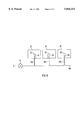
- FIG. 5 shows a fourth embodiment of a monitoring circuit according to the present invention.
- FIG. 1 shows a contact arrangement for a three-pole contactor in which contact arrangements 10, 20, and 30, each including two fixed contact elements 11, 21, 31 and 11', 21', 31' that are soldered onto contact supports 12, 22, and 32 and 12', 22', and 32', respectively.
- Countercontacts 14, 24, 34 and 14', 24', 34', which are each soldered onto a movable contact bridge 15, 25, and 35 will not be discussed in detail in this context.
- the measuring means described hereinafter could also be installed on the moving contacts.
- a single insulated signal line 300 which passes through the individual contacts and forms a closed signal line circuit is present in FIG. 1. Through holes can be present for this purpose in the individual contacts 11, 21, 31 and 11', 21', 31'. It is also possible to guide signal line 300 between the individual contacts and the contact supports. Milled recesses or grooves can optionally be provided in the contacts.
- a contact element 1 that is soldered onto a contact support 2 is equipped with a groove 3a in which an insulated signal line, consisting of an insulator 3 and a metal conductor 4, is located.
- Conductor 4 is connected, via an indicator 5 and a protective resistor 6, to the neutral conductor or another phase of the switched system.
- Insulator 3 in FIG. 2 can consist in particular of a glass-fiber sheath.
- a limited current flow occurs via protective resistor 6 and directly activates indicator 5, for example a light-emitting diode (LED).
- LED light-emitting diode
- Height h of the groove in FIG. 2 thus directly defines the erosion state at which, for example, an "X percent remaining service life” indicator can be activated.
- FIG. 3 a U-shaped loop of an insulated wire is laid into groove 3a: this arrangement can consist of a metal-sheathed tube 7 with two wires 8 and 9 installed therein, insulated from one another and also from the sheath.
- the latter arrangement is implemented by, for example, an ungrounded sheathed thermocouple.
- sheathed thermocouples of this kind the outside diameter of sheath 7 is typically 1 mm.
- FIG. 3a shows a plan view, the conductor ends of the U-shaped loops being designated 8a and 9b.
- a current 2 flows continuously from the contact bridge through indicator 5, both conductors 8, 9 of the sheathed thermocouple, and the limiting resistor 6, to the neutral conductor or another phase in the switched device.
- indicator 5 for example a light-emitting diode (LED)
- LED light-emitting diode
- FIG. 4 shows a fixed contact bridge 2 with a contact element 1 on the rear side of which a metal conductor 4 extends in an insulator 3 and has connector ends 4a and 4b.
- a current flows from contact bridge 2 through indicator 5, metal conductor 4, and the protective resistor to neutral or to another phase. In this case, the fact that the remaining service life has not yet been reached is indicated.
- current flow to the indicator is interrupted. This applies both to the case of a simple interruption of conductor 4 and to the case in which conductor 4 additionally makes contact with contact element 1 and thereby short-circuits indicator 5.
- An advantage of the exemplified embodiments described is that the cost outlay is comparatively low, and is determined solely by installation of the signal line in the switch contact.
- FIGS. 2-4 The arrangements described with reference to the embodiments shown in FIGS. 2-4 can be designed for multi-phase contactors as illustrated in FIG 1. It is particularly advantageous in this context that only a single signal line is necessary.
- FIG. 5 shows an arrangement with three contact elements 41, 51, and 61, each of which has on the rear side a blind hole 42, 52, and 62. Signal lines are introduced into blind holes 42, 52, and 62 by means of suitable insulators 43, 53, and 63.
- a single measuring wire 100 can be guided from indicator device 5 in such a way that the respective branch 104, 105, and 106 for contact elements 41, 51, and 61 is guided in doubled or U-shaped fashion, corresponding to the sheathed thermocouple of FIG. 3a.
- the double wire configuration guarantees the reliability of the indicator even if destruction is only partial.
- parallel monitoring is possible.
- many contacts can be monitored simultaneously and economically by means of a single arrangement.
Abstract
A switching device including a measuring means for monitoring contact erosion, which is provided between a contact element and an associated contact support. The switching device includes an electrically insulated signal line, which is usable in individual and/or multiple contacts, is used as the measuring means, the signal line being integrated into a single monitoring circuit. In the switching device, there is arranged, between at least one of the contact elements and the associated contact support or in the contact material, an electrical conductor with insulator as the signal line, damage to or destruction of the insulator and/or the conductor being utilized to generate an external signal as an indication of the end of the service life of the contact element.
Description
The present invention relates to a switching device, in particular a contactor or circuit breaker, having contact elements that are mounted in a switching device housing on contact supports, and having an electrically insulated signal line as means for monitoring contact erosion, damage to or destruction of the insulator and/or the conductor being utilized to generate an external signal as an indication of the end of the service life of at least one of the contact elements.
The service life of switching contact elements is determined by erosion, i.e. by the gradual loss of contact material under the influence of the arc which occurs in the switching operation. Erosion will generally wear away the contact elements in non-uniform fashion. The service life ends when the contact material has either completely eroded away or has been removed to a defined minimum thickness at least at one point in the contact region.
At present, the state of the switch contact elements can be assessed in practice only by opening the switching device and by visual inspection. This is particularly true for the remaining expected service life, a knowledge of which is of central importance for the functionality of the switching device and thus for the operating reliability of the load unit being switched.
DE-OS 40 28 721 discloses a method for determining the remaining service life of switching devices, in which the charge that has flowed during a switching operation is electronically determined and summed for the switching operations. This method is in principle suitable not only for indicating a defined remaining service life, but moreover also for indicating the erosion state of the contact elements at any desired point in time. A comparatively large outlay for the associated electronics is necessary, however, so that profitability may exist only for large switching devices.
In addition, an earlier international patent application (PCT/DE 94/00244) that was not pre-published describes a switching device in which the contact elements are slotted on the rear side and installed on a split contact support. The remaining service life of the contact can be determined with this arrangement: when erosion has eroded away the material located over the slot, two contact halves are created. When switching takes place in this condition, a potential difference occurs between the two contact halves; this is measured as a voltage, and can be used as an indication of contact erosion. Lastly, Germany Patent Application No. 37 14 802 also describes an electronic switch in which a light guide, the transmission properties of which can be measured from outside by means of suitable auxiliary optical equipment, is associated with at least one of the contact elements. The intention in this context is that contact erosion which has progressed impermissibly leads to a change in optical transmission properties and ultimately to destruction of the light guide. In particular, provision is made that each of the contact elements must be fitted with a light guide of this kind.
Accordingly, it is an object of the present invention to provide a switching device with which detection and indication of a defined remaining service life during operation of the switching device are guaranteed in absolutely reliable fashion for all the contact arrangements together. In particular, implementation is to be economical even for smaller switching devices.
This object is achieved, according to the present invention, using an electrical signal line which is guided in a U-shape between the contact elements and the associated contact supports or in the contact material itself.
The insulated signal line consists either of doubly guided wires or a U-shaped loop with two insulated supply leads. In this context, the U-shaped loops of a measuring wire can be guided, insulated from one another, preferably in a metal-sheathed tube. Such lines are previously known, for example, as ungrounded sheathed thermocouples, and can to that extent be used according to the present invention for the present purpose.
In the present invention, the contact element can have on its rear-side soldering surface a groove, a blind hole, or other orifices into which the insulated signal line can be inserted. The insulator can consist, in particular, of a glass-fiber sheath or another temperature-resistant insulator.
The present invention provides an arrangement which guarantees optimum functional reliability under all operating conditions. Multipole switching devices in particular can thereby be monitored for erosion in suitable fashion; wear on a contact element usually results in an indication that does not need to be localized to a specific contact element.
FIG. 1 shows a three-pole grounded contact arrangement with monitoring means arranged in a single circuit.
FIG. 2 shows a first embodiment of a monitoring circuit according to the present invention.
FIG. 3 shows a second embodiment of a monitoring circuit according to the present invention.
FIG. 4 shows a third embodiment of a monitoring circuit according to the present invention.
FIG. 5 shows a fourth embodiment of a monitoring circuit according to the present invention.
FIG. 1 shows a contact arrangement for a three-pole contactor in which contact arrangements 10, 20, and 30, each including two fixed contact elements 11, 21, 31 and 11', 21', 31' that are soldered onto contact supports 12, 22, and 32 and 12', 22', and 32', respectively. Countercontacts 14, 24, 34 and 14', 24', 34', which are each soldered onto a movable contact bridge 15, 25, and 35 will not be discussed in detail in this context. In principle, the measuring means described hereinafter could also be installed on the moving contacts.
A single insulated signal line 300 which passes through the individual contacts and forms a closed signal line circuit is present in FIG. 1. Through holes can be present for this purpose in the individual contacts 11, 21, 31 and 11', 21', 31'. It is also possible to guide signal line 300 between the individual contacts and the contact supports. Milled recesses or grooves can optionally be provided in the contacts.
In FIG. 2, a contact element 1 that is soldered onto a contact support 2 is equipped with a groove 3a in which an insulated signal line, consisting of an insulator 3 and a metal conductor 4, is located. Conductor 4 is connected, via an indicator 5 and a protective resistor 6, to the neutral conductor or another phase of the switched system.
Height h of the groove in FIG. 2 thus directly defines the erosion state at which, for example, an "X percent remaining service life" indicator can be activated.
In FIG. 3, a U-shaped loop of an insulated wire is laid into groove 3a: this arrangement can consist of a metal-sheathed tube 7 with two wires 8 and 9 installed therein, insulated from one another and also from the sheath. The latter arrangement is implemented by, for example, an ungrounded sheathed thermocouple. In sheathed thermocouples of this kind, the outside diameter of sheath 7 is typically 1 mm. The enlargement in FIG. 3a shows a plan view, the conductor ends of the U-shaped loops being designated 8a and 9b.
In the example according to FIG. 3, a current 2 flows continuously from the contact bridge through indicator 5, both conductors 8, 9 of the sheathed thermocouple, and the limiting resistor 6, to the neutral conductor or another phase in the switched device. In this case, activation of indicator 5, for example a light-emitting diode (LED), means that the remaining service life has not yet been reached.
Destruction of the sheathed element by erosion extinguishes indicator 5 as soon as conductor 9 is either separated from conductor 8 and/or makes contact with sheath 7.
FIG. 4 shows a fixed contact bridge 2 with a contact element 1 on the rear side of which a metal conductor 4 extends in an insulator 3 and has connector ends 4a and 4b. As long as insulator 3 is intact, a current flows from contact bridge 2 through indicator 5, metal conductor 4, and the protective resistor to neutral or to another phase. In this case, the fact that the remaining service life has not yet been reached is indicated. As soon as the switching arc destroys insulator 3 and conductor 4, current flow to the indicator is interrupted. This applies both to the case of a simple interruption of conductor 4 and to the case in which conductor 4 additionally makes contact with contact element 1 and thereby short-circuits indicator 5.
An advantage of the exemplified embodiments described is that the cost outlay is comparatively low, and is determined solely by installation of the signal line in the switch contact. By connecting an indicating means to the contact support, for example, it is possible in this context to utilize the potential for indication purposes. In any case, the fact that the remaining service life of the switching device has been reached is detected and indicated.
The arrangements described with reference to the embodiments shown in FIGS. 2-4 can be designed for multi-phase contactors as illustrated in FIG 1. It is particularly advantageous in this context that only a single signal line is necessary.
FIG. 5 shows an arrangement with three contact elements 41, 51, and 61, each of which has on the rear side a blind hole 42, 52, and 62. Signal lines are introduced into blind holes 42, 52, and 62 by means of suitable insulators 43, 53, and 63. As shown in FIG. 5, for example, a single measuring wire 100 can be guided from indicator device 5 in such a way that the respective branch 104, 105, and 106 for contact elements 41, 51, and 61 is guided in doubled or U-shaped fashion, corresponding to the sheathed thermocouple of FIG. 3a.
The double wire configuration guarantees the reliability of the indicator even if destruction is only partial. In addition, parallel monitoring is possible. As a result, many contacts can be monitored simultaneously and economically by means of a single arrangement.
Claims (12)
1. A switching device, comprising:
a housing;
a contact element mounted in the housing on a contact support; and
an electrically insulated signal line for monitoring contact erosion,
wherein, when the electrically insulated signal line is damaged, an external signal is generated indicating that a service life of the contact element has ended, and
wherein the electrically insulated signal line is guided in a U-shape between the contact element and the associated contact support.
2. The switching device according to claim 1, wherein, in a multiple phase system with a neutral conductor, the electrically insulated signal line is connected to one of a neutral conductor and to another phase via an indicating device and via an associated protective resistor.
3. The switching device according to claim 1,
wherein the electrically insulated signal line is extended in a U-shape over an entire rear side of the contacting element,
wherein a first end of the electrically insulated signal line is coupled to one of a neutral conductor and to another phase via a resistor, and
wherein a second end of the electrically insulated signal line is connected to the contact support via an indicating device.
4. The switching device according to claim 1, wherein the associated contact support is a fixed contact support that is utilized for indicating purposes.
5. The switching device according to claim 1, wherein the contact element has a rear-side soldering surface with a groove on the rear-side soldering surface, and wherein the electrically insulated signal line extends in a U-shape.
6. The switching device according to claim 1, wherein the electrically insulated signal line includes and insulator being composed of one of a glass-fiber sheath and another temperature-resistant insulator.
7. The switching device according to claim 5, wherein the groove has a height for indicating a remaining amount of a freely selectable remaining service life of the plurality of contact elements.
8. The switching device according to claim 5, wherein the switching device is one of a contactor and a circuit breaker.
9. The switching device according to claim 1, wherein the electrically insulated signal line that is guided in a U-shape includes a U-shape loop and two supply leads insulated from one another.
10. The switching device according to claim 9, wherein the U-shaped loop is guided in an insulated manner in a metal-sheathed tube.
11. The switching device according to claim 10, wherein the U-shaped loop in the metal-sheathed tube is implemented as an ungrounded sheathed thermocouple.
12. The switching device according to claim 11, wherein a first lead of the two supply leads coupled to the U-shaped loop is connected to one of the neutral conductor and a different phase via a protective resistor, and wherein a second lead of the two supply leads is connected to the associated contact support via an indicating device.
Applications Claiming Priority (3)
| Application Number | Priority Date | Filing Date | Title |
|---|---|---|---|
| DE4438475 | 1994-10-27 | ||
| DE4438475.0 | 1994-10-27 | ||
| PCT/DE1995/001483 WO1996013732A1 (en) | 1994-10-27 | 1995-10-25 | Process for monitoring the wear of at least one contact in a switching device and switching device designed therefor |
Publications (1)
| Publication Number | Publication Date |
|---|---|
| US5844331A true US5844331A (en) | 1998-12-01 |
Family
ID=6531886
Family Applications (1)
| Application Number | Title | Priority Date | Filing Date |
|---|---|---|---|
| US08/817,988 Expired - Lifetime US5844331A (en) | 1994-10-27 | 1995-10-25 | Process for monitoring the wear of at least one contact in a switching device and switching device designed thereof |
Country Status (5)
| Country | Link |
|---|---|
| US (1) | US5844331A (en) |
| EP (1) | EP0787305B1 (en) |
| CN (1) | CN1088197C (en) |
| DE (1) | DE59502186D1 (en) |
| WO (1) | WO1996013732A1 (en) |
Cited By (11)
| Publication number | Priority date | Publication date | Assignee | Title |
|---|---|---|---|---|
| US6076411A (en) * | 1996-12-09 | 2000-06-20 | Advent Engineering Services, Inc. | Method and apparatus for determining remaining life of conductor insulation systems through void size and density correlation |
| EP1049118A2 (en) * | 1999-04-28 | 2000-11-02 | Texas Instruments Incorporated | Electrical apparatus having improved electrical contact and electrical contact used therewith |
| US6777948B2 (en) | 2002-09-11 | 2004-08-17 | Electric Power Research Institute, Inc. | Method and apparatus for detecting wear in components of high voltage electrical equipment |
| US20050104598A1 (en) * | 2002-09-11 | 2005-05-19 | Nicola Dominelli | Method and apparatus for detecting wear in components of high voltage electrical equipment |
| US20050122117A1 (en) * | 2001-12-21 | 2005-06-09 | Schneider Electric Industries Sas | Method for determining wear of a switchgear contacts |
| US20070001677A1 (en) * | 2003-09-29 | 2007-01-04 | Bernd Adam | Device for detecting contact wear in switching appliances |
| US20070030607A1 (en) * | 2005-08-08 | 2007-02-08 | Liscinsky Stephen M Iii | Ground fault circuit interrupter (GFCI) end-of-life (EOL) status indicator |
| US20090063063A1 (en) * | 2003-09-08 | 2009-03-05 | Cooper Technologies Company | Preventive Maintenance Tapping and Duty Cycle Monitor for Voltage Regulator |
| CN106644368A (en) * | 2017-02-06 | 2017-05-10 | 中国航天空气动力技术研究院 | Monitoring device and discrimination method for discriminating collision of tail of large slenderness ratio model and support rod |
| US20180061599A1 (en) * | 2016-08-26 | 2018-03-01 | Panasonic Intellectual Property Management Co., Ltd. | Contact device, housing case used for contact device, and electromagnetic relay equipped with contact device |
| US10998144B2 (en) * | 2019-09-11 | 2021-05-04 | Arc Suppression Technologies | Power contact electrode surface plasma therapy |
Families Citing this family (5)
| Publication number | Priority date | Publication date | Assignee | Title |
|---|---|---|---|---|
| DE29720912U1 (en) * | 1997-11-25 | 1998-01-22 | Siemens Ag | Device for monitoring the contact wear of a contact piece |
| DE10003918C1 (en) | 2000-01-29 | 2001-07-05 | Reinhausen Maschf Scheubeck | Monitoring step switch contact burning involves deriving contact burning rates from switching currents, summing, converting to contact thickness, comparing with stored limit values |
| DE10352580B3 (en) * | 2003-11-11 | 2005-04-28 | Reinhausen Maschf Scheubeck | Stepping switch contact wear monitoring method e.g. for transformer step voltage regulator, with different equations used for calculation of switching currents and wear rates for each switching direction |
| DE102014200681A1 (en) * | 2014-01-16 | 2015-07-16 | Robert Bosch Gmbh | Switching device for switching high electrical currents and battery system with such a switching device |
| DE102017213266A1 (en) * | 2017-08-01 | 2019-02-07 | Siemens Aktiengesellschaft | Switch, in particular low-voltage circuit breaker, with a signaling of the wear of its contact pads and means for signaling the wear |
Citations (13)
| Publication number | Priority date | Publication date | Assignee | Title |
|---|---|---|---|---|
| DE656271C (en) * | 1935-11-29 | 1938-02-03 | Aeg | Electrical switching device whose fixed switching contacts, which are provided with burn-off rings, cannot be monitored easily |
| DE1174877B (en) * | 1963-08-14 | 1964-07-30 | Siemens Ag | Circuit breaker |
| DE7320355U (en) * | 1973-05-30 | 1976-12-09 | W.C. Heraeus Gmbh, 6450 Hanau | COAT THERMOCOUPLE |
| DE2728355A1 (en) * | 1976-06-25 | 1977-12-29 | British Nuclear Fuels Ltd | MONITORING SYSTEM |
| DE3337553A1 (en) * | 1982-10-25 | 1984-04-26 | ASEA AB, 72183 Västerås | ARRANGEMENT FOR MONITORING CONTACT COMBUSTION IN AN ELECTRICAL DEVICE |
| DE3714802A1 (en) * | 1987-05-04 | 1988-11-17 | Siemens Ag | Electrical switch |
| JPH03295116A (en) * | 1990-04-11 | 1991-12-26 | Omron Corp | Contact device |
| DE4028721A1 (en) * | 1990-09-10 | 1992-03-12 | Siemens Ag | Determining remaining life of switching devices - by integrating contact current during period between switching path threshold values and comparing with device special charge limit value |
| US5250909A (en) * | 1992-05-21 | 1993-10-05 | Benz Companies, Inc. | Automatic fault detection system in electrical sensing circuit |
| WO1994022153A1 (en) * | 1993-03-22 | 1994-09-29 | Siemens Aktiengesellschaft | Switching component, especially safety or power switch |
| US5420571A (en) * | 1994-01-11 | 1995-05-30 | Honeywell Inc. | Switch with end of life prediction capability |
| US5453591A (en) * | 1994-04-05 | 1995-09-26 | Abb Power T&D Company Inc. | Sensing structure for component wear in high voltage circuit interrupters |
| US5488530A (en) * | 1993-04-22 | 1996-01-30 | Mcdonnell Douglas Corporation | System and method for protecting relay contacts |
-
1995
- 1995-10-25 EP EP95935806A patent/EP0787305B1/en not_active Expired - Lifetime
- 1995-10-25 DE DE59502186T patent/DE59502186D1/en not_active Expired - Fee Related
- 1995-10-25 US US08/817,988 patent/US5844331A/en not_active Expired - Lifetime
- 1995-10-25 CN CN95195848A patent/CN1088197C/en not_active Expired - Fee Related
- 1995-10-25 WO PCT/DE1995/001483 patent/WO1996013732A1/en active IP Right Grant
Patent Citations (14)
| Publication number | Priority date | Publication date | Assignee | Title |
|---|---|---|---|---|
| DE656271C (en) * | 1935-11-29 | 1938-02-03 | Aeg | Electrical switching device whose fixed switching contacts, which are provided with burn-off rings, cannot be monitored easily |
| DE1174877B (en) * | 1963-08-14 | 1964-07-30 | Siemens Ag | Circuit breaker |
| DE7320355U (en) * | 1973-05-30 | 1976-12-09 | W.C. Heraeus Gmbh, 6450 Hanau | COAT THERMOCOUPLE |
| DE2728355A1 (en) * | 1976-06-25 | 1977-12-29 | British Nuclear Fuels Ltd | MONITORING SYSTEM |
| DE3337553A1 (en) * | 1982-10-25 | 1984-04-26 | ASEA AB, 72183 Västerås | ARRANGEMENT FOR MONITORING CONTACT COMBUSTION IN AN ELECTRICAL DEVICE |
| DE3714802A1 (en) * | 1987-05-04 | 1988-11-17 | Siemens Ag | Electrical switch |
| JPH03295116A (en) * | 1990-04-11 | 1991-12-26 | Omron Corp | Contact device |
| DE4028721A1 (en) * | 1990-09-10 | 1992-03-12 | Siemens Ag | Determining remaining life of switching devices - by integrating contact current during period between switching path threshold values and comparing with device special charge limit value |
| US5250909A (en) * | 1992-05-21 | 1993-10-05 | Benz Companies, Inc. | Automatic fault detection system in electrical sensing circuit |
| WO1994022153A1 (en) * | 1993-03-22 | 1994-09-29 | Siemens Aktiengesellschaft | Switching component, especially safety or power switch |
| US5747984A (en) * | 1993-03-22 | 1998-05-05 | Siemens Aktiengesellschaft | Switching component for detecting contact erosion |
| US5488530A (en) * | 1993-04-22 | 1996-01-30 | Mcdonnell Douglas Corporation | System and method for protecting relay contacts |
| US5420571A (en) * | 1994-01-11 | 1995-05-30 | Honeywell Inc. | Switch with end of life prediction capability |
| US5453591A (en) * | 1994-04-05 | 1995-09-26 | Abb Power T&D Company Inc. | Sensing structure for component wear in high voltage circuit interrupters |
Cited By (19)
| Publication number | Priority date | Publication date | Assignee | Title |
|---|---|---|---|---|
| US6076411A (en) * | 1996-12-09 | 2000-06-20 | Advent Engineering Services, Inc. | Method and apparatus for determining remaining life of conductor insulation systems through void size and density correlation |
| EP1049118A2 (en) * | 1999-04-28 | 2000-11-02 | Texas Instruments Incorporated | Electrical apparatus having improved electrical contact and electrical contact used therewith |
| EP1049118A3 (en) * | 1999-04-28 | 2002-07-10 | Texas Instruments Incorporated | Electrical apparatus having improved electrical contact and electrical contact used therewith |
| US20050122117A1 (en) * | 2001-12-21 | 2005-06-09 | Schneider Electric Industries Sas | Method for determining wear of a switchgear contacts |
| US7109720B2 (en) * | 2001-12-21 | 2006-09-19 | Schneider Electric Industries Sas | Method for determining wear of a switchgear contacts |
| US6777948B2 (en) | 2002-09-11 | 2004-08-17 | Electric Power Research Institute, Inc. | Method and apparatus for detecting wear in components of high voltage electrical equipment |
| US20050104598A1 (en) * | 2002-09-11 | 2005-05-19 | Nicola Dominelli | Method and apparatus for detecting wear in components of high voltage electrical equipment |
| US7053625B2 (en) | 2002-09-11 | 2006-05-30 | Electric Power Research Institute, Inc. | Method and apparatus for detecting wear in components of high voltage electrical equipment |
| US20090063063A1 (en) * | 2003-09-08 | 2009-03-05 | Cooper Technologies Company | Preventive Maintenance Tapping and Duty Cycle Monitor for Voltage Regulator |
| US7915766B2 (en) * | 2003-09-08 | 2011-03-29 | Cooper Technologies Company | Preventive maintenance tapping and duty cycle monitor for voltage regulator |
| AU2009225315B2 (en) * | 2003-09-08 | 2012-03-01 | Cooper Technologies Company | Preventive maintenance tapping and duty cycle monitor for voltage regulator |
| US7408357B2 (en) * | 2003-09-29 | 2008-08-05 | Siemens Aktiengesellschaft | Device for detecting contact wear in switching appliances |
| US20070001677A1 (en) * | 2003-09-29 | 2007-01-04 | Bernd Adam | Device for detecting contact wear in switching appliances |
| US20070030607A1 (en) * | 2005-08-08 | 2007-02-08 | Liscinsky Stephen M Iii | Ground fault circuit interrupter (GFCI) end-of-life (EOL) status indicator |
| US7336457B2 (en) | 2005-08-08 | 2008-02-26 | Hubbell Incorporated | Ground fault circuit interrupter (GFCI) end-of-life (EOL) status indicator |
| US20180061599A1 (en) * | 2016-08-26 | 2018-03-01 | Panasonic Intellectual Property Management Co., Ltd. | Contact device, housing case used for contact device, and electromagnetic relay equipped with contact device |
| CN106644368A (en) * | 2017-02-06 | 2017-05-10 | 中国航天空气动力技术研究院 | Monitoring device and discrimination method for discriminating collision of tail of large slenderness ratio model and support rod |
| US10998144B2 (en) * | 2019-09-11 | 2021-05-04 | Arc Suppression Technologies | Power contact electrode surface plasma therapy |
| US11562863B2 (en) | 2019-09-11 | 2023-01-24 | Arc Suppression Technologies | Power contact electrode surface plasma therapy |
Also Published As
| Publication number | Publication date |
|---|---|
| EP0787305B1 (en) | 1998-05-13 |
| CN1088197C (en) | 2002-07-24 |
| WO1996013732A1 (en) | 1996-05-09 |
| CN1161749A (en) | 1997-10-08 |
| DE59502186D1 (en) | 1998-06-18 |
| EP0787305A1 (en) | 1997-08-06 |
Similar Documents
| Publication | Publication Date | Title |
|---|---|---|
| US5844331A (en) | Process for monitoring the wear of at least one contact in a switching device and switching device designed thereof | |
| FI82997C (en) | KRETSAVBRYTARE. | |
| US4087744A (en) | Device for determining a high-voltage potential in metal-encapsulated high-voltage switching installations and equipment | |
| EP2682971B1 (en) | A device for indicating the state of a switching apparatus | |
| CA2350514A1 (en) | Arc fault circuit breaker | |
| KR19980041947A (en) | Electrical switching device | |
| US4532499A (en) | Means for detecting the contact wear of electrical switching devices | |
| US20050128661A1 (en) | Method and device for protecting a conductor when an electric arc is produced | |
| KR20000036000A (en) | Electrical contact wear and temperature indicator | |
| EP0356017A2 (en) | Liquid leakage detection apparatus | |
| KR920009352B1 (en) | Control system and selector device for a contactor apparatus | |
| CA2387022C (en) | Circuit breaker with shunt | |
| US7408357B2 (en) | Device for detecting contact wear in switching appliances | |
| US6777948B2 (en) | Method and apparatus for detecting wear in components of high voltage electrical equipment | |
| KR890007082A (en) | Automatic Short Circuit Tester Control | |
| US7090801B2 (en) | Monitoring device for melting furnaces | |
| JPH06124749A (en) | Connecting part having overheat detecting function for electric equipment and overheat monitoring device for electric equipment | |
| EP0160440A1 (en) | Apparatus for detecting and obtaining imformation about changes in variables | |
| US3876948A (en) | Fuse alarm indicator | |
| EP0292939B1 (en) | Warp yarn breakage detecting and indicating apparatus | |
| EP0313709A1 (en) | Status-indicating fuse for D.C. current electrical systems | |
| JPS62277567A (en) | Detecting method for temperature abnormality | |
| KR0119860Y1 (en) | Thermal sensing wire inserting cable | |
| JPH10117429A (en) | Non-tracking receptacle | |
| KR20020022082A (en) | Power distributor of respective cut-out type |
Legal Events
| Date | Code | Title | Description |
|---|---|---|---|
| AS | Assignment |
Owner name: SIEMENS AKTIENGESELLSCHAFT, GERMANY Free format text: ASSIGNMENT OF ASSIGNORS INTEREST;ASSIGNORS:KIESER, JORG;BRANSTON, DAVID-WALTER;MAIER, REINHARD;AND OTHERS;REEL/FRAME:008945/0106;SIGNING DATES FROM 19970606 TO 19970611 |
|
| STCF | Information on status: patent grant |
Free format text: PATENTED CASE |
|
| FEPP | Fee payment procedure |
Free format text: PAYOR NUMBER ASSIGNED (ORIGINAL EVENT CODE: ASPN); ENTITY STATUS OF PATENT OWNER: LARGE ENTITY |
|
| FPAY | Fee payment |
Year of fee payment: 4 |
|
| REMI | Maintenance fee reminder mailed | ||
| FPAY | Fee payment |
Year of fee payment: 8 |
|
| FPAY | Fee payment |
Year of fee payment: 12 |