US5821720A - Backlash elimination in the drivetrain of an electric vehicle - Google Patents
Backlash elimination in the drivetrain of an electric vehicle Download PDFInfo
- Publication number
- US5821720A US5821720A US08/846,442 US84644297A US5821720A US 5821720 A US5821720 A US 5821720A US 84644297 A US84644297 A US 84644297A US 5821720 A US5821720 A US 5821720A
- Authority
- US
- United States
- Prior art keywords
- drivetrain
- torque
- vehicle
- applying
- brakes
- Prior art date
- Legal status (The legal status is an assumption and is not a legal conclusion. Google has not performed a legal analysis and makes no representation as to the accuracy of the status listed.)
- Expired - Lifetime
Links
Images

Classifications
-
- B—PERFORMING OPERATIONS; TRANSPORTING
- B60—VEHICLES IN GENERAL
- B60W—CONJOINT CONTROL OF VEHICLE SUB-UNITS OF DIFFERENT TYPE OR DIFFERENT FUNCTION; CONTROL SYSTEMS SPECIALLY ADAPTED FOR HYBRID VEHICLES; ROAD VEHICLE DRIVE CONTROL SYSTEMS FOR PURPOSES NOT RELATED TO THE CONTROL OF A PARTICULAR SUB-UNIT
- B60W30/00—Purposes of road vehicle drive control systems not related to the control of a particular sub-unit, e.g. of systems using conjoint control of vehicle sub-units, or advanced driver assistance systems for ensuring comfort, stability and safety or drive control systems for propelling or retarding the vehicle
- B60W30/18—Propelling the vehicle
-
- B—PERFORMING OPERATIONS; TRANSPORTING
- B60—VEHICLES IN GENERAL
- B60W—CONJOINT CONTROL OF VEHICLE SUB-UNITS OF DIFFERENT TYPE OR DIFFERENT FUNCTION; CONTROL SYSTEMS SPECIALLY ADAPTED FOR HYBRID VEHICLES; ROAD VEHICLE DRIVE CONTROL SYSTEMS FOR PURPOSES NOT RELATED TO THE CONTROL OF A PARTICULAR SUB-UNIT
- B60W10/00—Conjoint control of vehicle sub-units of different type or different function
- B60W10/04—Conjoint control of vehicle sub-units of different type or different function including control of propulsion units
- B60W10/08—Conjoint control of vehicle sub-units of different type or different function including control of propulsion units including control of electric propulsion units, e.g. motors or generators
-
- B—PERFORMING OPERATIONS; TRANSPORTING
- B60—VEHICLES IN GENERAL
- B60W—CONJOINT CONTROL OF VEHICLE SUB-UNITS OF DIFFERENT TYPE OR DIFFERENT FUNCTION; CONTROL SYSTEMS SPECIALLY ADAPTED FOR HYBRID VEHICLES; ROAD VEHICLE DRIVE CONTROL SYSTEMS FOR PURPOSES NOT RELATED TO THE CONTROL OF A PARTICULAR SUB-UNIT
- B60W10/00—Conjoint control of vehicle sub-units of different type or different function
- B60W10/18—Conjoint control of vehicle sub-units of different type or different function including control of braking systems
- B60W10/184—Conjoint control of vehicle sub-units of different type or different function including control of braking systems with wheel brakes
-
- B—PERFORMING OPERATIONS; TRANSPORTING
- B60—VEHICLES IN GENERAL
- B60K—ARRANGEMENT OR MOUNTING OF PROPULSION UNITS OR OF TRANSMISSIONS IN VEHICLES; ARRANGEMENT OR MOUNTING OF PLURAL DIVERSE PRIME-MOVERS IN VEHICLES; AUXILIARY DRIVES FOR VEHICLES; INSTRUMENTATION OR DASHBOARDS FOR VEHICLES; ARRANGEMENTS IN CONNECTION WITH COOLING, AIR INTAKE, GAS EXHAUST OR FUEL SUPPLY OF PROPULSION UNITS IN VEHICLES
- B60K1/00—Arrangement or mounting of electrical propulsion units
-
- B—PERFORMING OPERATIONS; TRANSPORTING
- B60—VEHICLES IN GENERAL
- B60W—CONJOINT CONTROL OF VEHICLE SUB-UNITS OF DIFFERENT TYPE OR DIFFERENT FUNCTION; CONTROL SYSTEMS SPECIALLY ADAPTED FOR HYBRID VEHICLES; ROAD VEHICLE DRIVE CONTROL SYSTEMS FOR PURPOSES NOT RELATED TO THE CONTROL OF A PARTICULAR SUB-UNIT
- B60W2510/00—Input parameters relating to a particular sub-units
- B60W2510/08—Electric propulsion units
- B60W2510/081—Speed
-
- B—PERFORMING OPERATIONS; TRANSPORTING
- B60—VEHICLES IN GENERAL
- B60W—CONJOINT CONTROL OF VEHICLE SUB-UNITS OF DIFFERENT TYPE OR DIFFERENT FUNCTION; CONTROL SYSTEMS SPECIALLY ADAPTED FOR HYBRID VEHICLES; ROAD VEHICLE DRIVE CONTROL SYSTEMS FOR PURPOSES NOT RELATED TO THE CONTROL OF A PARTICULAR SUB-UNIT
- B60W2540/00—Input parameters relating to occupants
- B60W2540/10—Accelerator pedal position
-
- B—PERFORMING OPERATIONS; TRANSPORTING
- B60—VEHICLES IN GENERAL
- B60W—CONJOINT CONTROL OF VEHICLE SUB-UNITS OF DIFFERENT TYPE OR DIFFERENT FUNCTION; CONTROL SYSTEMS SPECIALLY ADAPTED FOR HYBRID VEHICLES; ROAD VEHICLE DRIVE CONTROL SYSTEMS FOR PURPOSES NOT RELATED TO THE CONTROL OF A PARTICULAR SUB-UNIT
- B60W2710/00—Output or target parameters relating to a particular sub-units
- B60W2710/08—Electric propulsion units
- B60W2710/083—Torque
Definitions
- the present invention relates to elimination of backlash in the drivetrain of an electrically-propelled vehicle.
- a simple single-speed transmission can be used.
- Such a transmission can be used because, unlike an internal combustion engine, an electric motor can operate over a very wide rotational speed range.
- a multiple-speed transmission for converting from an internal combustion engine's relatively narrow speed range to a wider vehicle speed range is not necessary.
- a single-speed transmission has several benefits, including simplicity, reliability and low cost.
- the gears of the transmission may be subject to "backlash", wherein the mating teeth of two gears (a driving gear and a driven gear) are not in contact when the driving gear begins to move.
- backlash When such a backlash condition exists, the driving gear will accelerate quickly before its teeth are in contact with the teeth of the driven gear. The result can be a significant impact between the teeth of the gears when the teeth finally come into contact.
- the impact can introduce a significant torsional oscillation into the vehicle's drivetrain, particularly at the drivetrain's torsional resonant frequency.
- the oscillation in turn can translate into customer dissatisfaction with the driveability of his vehicle.
- a system which can reduce or eliminate backlash can improve customer satisfaction by reducing the resultant oscillation in the vehicle's drivetrain.
- a system which can reduce the oscillation introduced by any backlash which may occur will also improve customer satisfaction.
- the present invention provides a method for substantially eliminating backlash in drivetrain gears of a vehicle propelled by an electric motor.
- the method includes detecting whether brakes of the vehicle are applied.
- the method further comprises only if the brakes are applied, applying a torque from the electric motor to move at least some teeth of the gears into contact with one another.
- the present invention further provides a system for substantially eliminating backlash in a drivetrain of a motor vehicle.
- the system comprises a plurality of wheels and a drivetrain coupled to at least one of said wheels and comprising engaging gears.
- the system also includes brakes proximate to at least one of the wheels and adapted to selectively apply braking torque to the at least one of the wheels to which the brakes are proximate.
- the system comprises means coupled to the drivetrain for applying a torque only while the brakes are applied to move at least the teeth of the gears into contact with one another.
- Systems according to the present invention can very effectively reduce or eliminate backlash between gears of a vehicle drivetrain. In doing so, drivetrain oscillation resulting from such backlash will be reduced or eliminated as well, improving vehicle driveability and customer satisfaction.
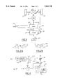
- FIG.1 is a block diagram of the powertrain and powertrain controls of an electrically-propelled vehicle.
- FIG. 2A illustrates two gears in a backlash condition.
- FIG. 2B illustrates two gears in a zero-backlash condition.
- FIG. 3 provides further detail of electronic controller 24 of FIG. 1.
- FIG. 4 provides further detail of backlash-elimination current generator 30 of FIG. 3.
- FIG. 1 where a block diagram of the powertrain and powertrain controls of an electric vehicle are illustrated.
- An electric motor 10 provides drive torque for the driving wheels 12 of the vehicle.
- a drivetrain which includes a transaxle 16 and driveshafts 18.
- Transaxle includes gearing selected to provide appropriate torque and rotational speed ratios between motor 10 and wheels 12.
- a battery 20 provides electric power for motor 10.
- the DC power from battery 20 is converted to AC power, typically three-phase power, by inverter 22.
- An electronic controller 24 provides gating control signals for the switching devices in inverter 22.
- Electronic controller 24 also contains control logic for converting a torque demand, generated by a position of acceleration pedal sensor 25, into a current command for motor 10.
- Feedback signals to electronic controller 24 include actual motor current signal 26 and drivetrain rotational speed ( ⁇ ) 28. Appropriate sensors are provided to generate these feedback signals.
- Electronic controller 24 is preferably a microprocessor-based device having appropriate inputs, outputs, throughput, memory and the like to perform the functions ascribed to it herein.
- transaxle 16 is preferably a single-speed transaxle. Such a transaxle has the considerable advantages of simplicity, reliability and relatively low cost.
- FIG. 2A shows a condition of backlash between a driving gear 27 and a driven gear 29.
- the rotational direction of driving gear 27 is shown by an arrow on that gear.
- driving gear 27 begins to turn, it will accelerate prior to its teeth contacting the teeth of driven gear 29.
- the teeth of driving gear 27 can thus "slap" the engaged teeth of driven gear 29, introducing a relatively large impact into the drivetrain of the vehicle.
- the drivetrain may then torsionally oscillate at its resonant frequency.
- FIG. 2B shows a situation where no backlash exists.
- the control system of FIG. 3 can be employed.
- Electronic controller 24 includes a backlash-eliminating current generator 30.
- Current generator 30 uses drivetrain rotational speed, brake on/off state and a predetermined backlash-eliminating reference torque as inputs and generates a backlash-eliminating current I rec as an output.
- Current I rec is added at summing block 32 to the current command I tqo , which represents the torque commanded by the driver pressing on the accelerator pedal of the vehicle. The result is I tq , a modified current command.
- Block 44 uses "brake on/off” (BOO) status derived from the brake switch of the vehicle. This can be either a discrete switch which simply gives ON/OFF status or an analog sensor which senses the amount that the brake pedal of the vehicle is depressed.
- the output of block 44 is a constant k 0 , which has a value of 1.0 if the brakes are applied and 0 if the brakes are not applied.
- k 0 is then preferably low-pass-filtered at block 46, to result in a constant k 1 .
- Block 50 uses as an input vehicle speed or drivetrain rotational speed, derived from an appropriate sensor or encoder.
- vehicle speed or drivetrain rotational speed derived from an appropriate sensor or encoder.
- a very small predetermined backlash-eliminating torque value T q--rec (chosen to be much less than the braking capability of the vehicle's brakes) is multiplied by an appropriate constant k 3 to convert T q--rec into units of electrical current.
- the output of block 52 is a backlash-eliminating current value I rec--O .
- I rec--O is then multiplied by k 2 at block 54 and by k 1 at block 56.
- the result of the calculations at blocks 54 and 56 is backlash-eliminating current command I rec , which is applied as illustrated in FIG. 3.
- the calculations illustrated in FIG. 4 are such that I rec is zero except when the brakes of the vehicle are applied and the vehicle's speed is extremely low.
- I rec provides torque which is just sufficient to keep the meshed gear teeth of transaxle 16 in contact, but not large enough to propel the vehicle. Due to the inclusion of I rec , the gear teeth in the drivetrain do not slap together with great impact at launch of the vehicle from rest. Drivetrain oscillations which might otherwise occur are therefore substantially prevented.
- Compensator 70 uses as an input drivetrain rotational speed, acquired from an appropriate sensor.
- Compensator 70 is a bandpass filter with a passing frequency band (f 1 , to f 2 ) which includes the torsional resonant frequency of the drivetrain of the vehicle.
- f 1 , to f 2 a passing frequency band which includes the torsional resonant frequency of the drivetrain of the vehicle.
- I comp an oscillation-compensating current I comp is generated only when the drivetrain rotational speed has a frequency component around the torsional resonant frequency of the drivetrain.
- compensator 70 will have no effect. None of those frequency components will pass.
- the preferred transfer function of compensator 70 is: ##EQU1## Gain G 1 , zero z 1 and poles p 1 and p 2 are selected to provide the transfer function illustrated in block 70 of FIG. 3.
- the output of compensator 70, I comp is combined with I tq at summing node 72.
- I ref the output of summing node 72, is provided to motor control block 74.
- Motor control block 74 represents any conventional motor control scheme. Motor control block 74 controls the switching of inverter 22 (selected from any appropriate conventional inverter design) to generate current I for motor 10 (FIG. 1). Current I is fed back to motor control block 74 (as is also conventional), so current I can be controlled to equal I ref .
Abstract
Description
Claims (13)
Priority Applications (1)
| Application Number | Priority Date | Filing Date | Title |
|---|---|---|---|
| US08/846,442 US5821720A (en) | 1997-04-30 | 1997-04-30 | Backlash elimination in the drivetrain of an electric vehicle |
Applications Claiming Priority (1)
| Application Number | Priority Date | Filing Date | Title |
|---|---|---|---|
| US08/846,442 US5821720A (en) | 1997-04-30 | 1997-04-30 | Backlash elimination in the drivetrain of an electric vehicle |
Publications (1)
| Publication Number | Publication Date |
|---|---|
| US5821720A true US5821720A (en) | 1998-10-13 |
Family
ID=25297951
Family Applications (1)
| Application Number | Title | Priority Date | Filing Date |
|---|---|---|---|
| US08/846,442 Expired - Lifetime US5821720A (en) | 1997-04-30 | 1997-04-30 | Backlash elimination in the drivetrain of an electric vehicle |
Country Status (1)
| Country | Link |
|---|---|
| US (1) | US5821720A (en) |
Cited By (10)
| Publication number | Priority date | Publication date | Assignee | Title |
|---|---|---|---|---|
| US6196345B1 (en) * | 1998-05-18 | 2001-03-06 | Bae Systems Controls, Inc. | Drive-line damping control for an electric vehicle |
| US6392377B1 (en) * | 1998-03-27 | 2002-05-21 | Canon Kabushiki Kaisha | Motor control apparatus and motor control method |
| US20030062859A1 (en) * | 2001-09-07 | 2003-04-03 | Notker Amann | Method and regulating system for damping the torque oscillations of the drive train of an electrically driven road vehicle |
| US20030216215A1 (en) * | 2002-03-08 | 2003-11-20 | Nissan Motor Co., Ltd. | Vehicle powertrain control system and method for enhanced vehicle start-up acceleration |
| US6838854B2 (en) * | 2000-09-25 | 2005-01-04 | Aisin Seiki Kabushiki Kaisha | Digital signal to pulse converter and method of digital signal to pulse conversion |
| US20050253543A1 (en) * | 2004-03-30 | 2005-11-17 | Christophe Soudier | Method, apparatus and article for vibration compensation in electric drivetrains |
| GB2490493A (en) * | 2011-04-28 | 2012-11-07 | Sevcon Ltd | Torque control apparatus for electric vehicle |
| US9654032B2 (en) | 2011-04-28 | 2017-05-16 | Sevcon Limited | Electric motor and motor controller |
| SE1751214A1 (en) * | 2017-10-02 | 2019-04-03 | Scania Cv Ab | Method and system for controlling at least one electrical machine |
| US11351976B2 (en) * | 2019-04-01 | 2022-06-07 | Hyundai Motor Company | Motor torque control method for motor-driven vehicle |
Citations (5)
| Publication number | Priority date | Publication date | Assignee | Title |
|---|---|---|---|---|
| US4210853A (en) * | 1977-06-10 | 1980-07-01 | Siemens Aktiengesellschaft | Control device with an integrating position drive |
| US4345195A (en) * | 1979-12-13 | 1982-08-17 | Sperry Corporation | Strapdown multifunction servoactuator apparatus for aircraft |
| US5008605A (en) * | 1987-01-12 | 1991-04-16 | Canon Kabushiki Kaisha | Electric driving device capable of eliminating backlash |
| US5253724A (en) * | 1991-10-25 | 1993-10-19 | Prior Ronald E | Power wheelchair with transmission using multiple motors per drive wheel |
| US5731673A (en) * | 1993-07-06 | 1998-03-24 | Black & Decker Inc. | Electrical power tool having a motor control circuit for increasing the effective torque output of the power tool |
-
1997
- 1997-04-30 US US08/846,442 patent/US5821720A/en not_active Expired - Lifetime
Patent Citations (5)
| Publication number | Priority date | Publication date | Assignee | Title |
|---|---|---|---|---|
| US4210853A (en) * | 1977-06-10 | 1980-07-01 | Siemens Aktiengesellschaft | Control device with an integrating position drive |
| US4345195A (en) * | 1979-12-13 | 1982-08-17 | Sperry Corporation | Strapdown multifunction servoactuator apparatus for aircraft |
| US5008605A (en) * | 1987-01-12 | 1991-04-16 | Canon Kabushiki Kaisha | Electric driving device capable of eliminating backlash |
| US5253724A (en) * | 1991-10-25 | 1993-10-19 | Prior Ronald E | Power wheelchair with transmission using multiple motors per drive wheel |
| US5731673A (en) * | 1993-07-06 | 1998-03-24 | Black & Decker Inc. | Electrical power tool having a motor control circuit for increasing the effective torque output of the power tool |
Cited By (18)
| Publication number | Priority date | Publication date | Assignee | Title |
|---|---|---|---|---|
| US6392377B1 (en) * | 1998-03-27 | 2002-05-21 | Canon Kabushiki Kaisha | Motor control apparatus and motor control method |
| US6196345B1 (en) * | 1998-05-18 | 2001-03-06 | Bae Systems Controls, Inc. | Drive-line damping control for an electric vehicle |
| US6838854B2 (en) * | 2000-09-25 | 2005-01-04 | Aisin Seiki Kabushiki Kaisha | Digital signal to pulse converter and method of digital signal to pulse conversion |
| US20030062859A1 (en) * | 2001-09-07 | 2003-04-03 | Notker Amann | Method and regulating system for damping the torque oscillations of the drive train of an electrically driven road vehicle |
| US6720746B2 (en) | 2001-09-07 | 2004-04-13 | Daimlerchrysler Ag | Method and regulating system for damping the torque oscillations of the drive train of an electrically driven road vehicle |
| EP1342610A3 (en) * | 2002-03-08 | 2007-03-21 | Nissan Motor Co., Ltd. | Vehicle powertrain control system and method for enhanced vehicle start-up acceleration |
| US6905438B2 (en) * | 2002-03-08 | 2005-06-14 | Nissan Motor Co., Ltd. | Vehicle powertrain control system and method for enhanced vehicle start-up acceleration |
| US20030216215A1 (en) * | 2002-03-08 | 2003-11-20 | Nissan Motor Co., Ltd. | Vehicle powertrain control system and method for enhanced vehicle start-up acceleration |
| US20050253543A1 (en) * | 2004-03-30 | 2005-11-17 | Christophe Soudier | Method, apparatus and article for vibration compensation in electric drivetrains |
| US7495403B2 (en) | 2004-03-30 | 2009-02-24 | Continental Automotive Systems Us, Inc. | Method, apparatus and article for vibration compensation in electric drivetrains |
| GB2490493A (en) * | 2011-04-28 | 2012-11-07 | Sevcon Ltd | Torque control apparatus for electric vehicle |
| GB2490493B (en) * | 2011-04-28 | 2013-04-17 | Sevcon Ltd | Motor controller with oscillation damping system |
| US9654032B2 (en) | 2011-04-28 | 2017-05-16 | Sevcon Limited | Electric motor and motor controller |
| US10761492B2 (en) | 2011-04-28 | 2020-09-01 | Sevcon Limited | Electric motor and motor controller |
| SE1751214A1 (en) * | 2017-10-02 | 2019-04-03 | Scania Cv Ab | Method and system for controlling at least one electrical machine |
| WO2019070179A1 (en) * | 2017-10-02 | 2019-04-11 | Scania Cv Ab | Method and system for controlling at least one electrical machine |
| US11780443B2 (en) | 2017-10-02 | 2023-10-10 | Scania Cv Ab | Method and system for controlling at least one electrical machine |
| US11351976B2 (en) * | 2019-04-01 | 2022-06-07 | Hyundai Motor Company | Motor torque control method for motor-driven vehicle |
Similar Documents
| Publication | Publication Date | Title |
|---|---|---|
| US5994859A (en) | Torsional oscillation compensation in the drivetrain of a motor vehicle | |
| US6377007B1 (en) | Motor torque control device of electric vehicle | |
| EP0925980A3 (en) | Vehicle drive system controller and control method | |
| US20080004780A1 (en) | Control apparatus and control method for hybrid vehicle | |
| US7374000B2 (en) | Electric generating system for automobiles and its control method | |
| US5471384A (en) | Electromobile | |
| JP2001158249A5 (en) | ||
| EP0943475A3 (en) | Hybrid vehicle drive force control device and control method | |
| EP0788914A3 (en) | Controller for vehicle | |
| US5821720A (en) | Backlash elimination in the drivetrain of an electric vehicle | |
| GB2289774A (en) | Drive control system for battery car | |
| EP0530381A4 (en) | Control device for internal combustion engine and continuously variable transmission | |
| US5839530A (en) | Process for operating a drive unit for vehicles or drive unit | |
| JPH09191507A (en) | Control device for electric motor vehicle | |
| JPS6189157A (en) | Driving slip control system | |
| EP0901933B1 (en) | Vibration control for a vehicle drivetrain | |
| JPH11182275A (en) | Operating cylinder number control device for hybrid vehicle | |
| JPH1118207A (en) | Braking controller for electric vehicle | |
| US11813943B2 (en) | Method and drive control device for operating at least two electric drive machines in the event of a change in load and motor vehicle with a drive control device | |
| EP0925979A3 (en) | Vehicle drive system | |
| JPH0439790Y2 (en) | ||
| JPH0993724A (en) | Electric automobile | |
| JP2745304B2 (en) | Acceleration / deceleration control method and device for electric vehicle | |
| CA1322979C (en) | Method for controlling braking of drive wheels for vehicle | |
| JP3588993B2 (en) | Hybrid vehicle control device |
Legal Events
| Date | Code | Title | Description |
|---|---|---|---|
| AS | Assignment |
Owner name: FORD MOTOR COMPANY, MICHIGAN Free format text: ASSIGNMENT OF ASSIGNORS INTEREST;ASSIGNORS:DENG, DOUG D.;XU, JACK H.;FARKAS, KENNETH JAMES;REEL/FRAME:008596/0760 Effective date: 19970429 |
|
| STCF | Information on status: patent grant |
Free format text: PATENTED CASE |
|
| AS | Assignment |
Owner name: ECOSTAR ELECTRIC DRIVE SYSTEMS L.L.C., A DELAWARE Free format text: ASSIGNMENT OF ASSIGNORS INTEREST;ASSIGNOR:FORD MOTOR COMPANY;REEL/FRAME:009827/0313 Effective date: 19990301 |
|
| FPAY | Fee payment |
Year of fee payment: 4 |
|
| AS | Assignment |
Owner name: BALLARD POWER SYSTEMS CORPORATION, MICHIGAN Free format text: CHANGE OF NAME;ASSIGNOR:ECOSTAR ELECTRIC DRIVE SYSTEMS, L.L.C.;REEL/FRAME:014192/0183 Effective date: 20011130 |
|
| FPAY | Fee payment |
Year of fee payment: 8 |
|
| AS | Assignment |
Owner name: SIEMENS VDO AUTOMOTIVE CORPORATION,MICHIGAN Free format text: CHANGE OF NAME;ASSIGNOR:BALLARD POWER SYSTEMS CORPORATION;REEL/FRAME:019077/0840 Effective date: 20070215 Owner name: SIEMENS VDO AUTOMOTIVE CORPORATION, MICHIGAN Free format text: CHANGE OF NAME;ASSIGNOR:BALLARD POWER SYSTEMS CORPORATION;REEL/FRAME:019077/0840 Effective date: 20070215 |
|
| FEPP | Fee payment procedure |
Free format text: PAYOR NUMBER ASSIGNED (ORIGINAL EVENT CODE: ASPN); ENTITY STATUS OF PATENT OWNER: LARGE ENTITY Free format text: PAYER NUMBER DE-ASSIGNED (ORIGINAL EVENT CODE: RMPN); ENTITY STATUS OF PATENT OWNER: LARGE ENTITY |
|
| FPAY | Fee payment |
Year of fee payment: 12 |
|
| AS | Assignment |
Owner name: CONTINENTAL AUTOMOTIVE SYSTEMS US, INC., MICHIGAN Free format text: CHANGE OF NAME;ASSIGNOR:SIEMENS VDO AUTOMOTIVE CORPORATION;REEL/FRAME:034979/0865 Effective date: 20071203 |
|
| AS | Assignment |
Owner name: CONTINENTAL AUTOMOTIVE SYSTEMS, INC., MICHIGAN Free format text: MERGER;ASSIGNOR:CONTINENTAL AUTOMOTIVE SYSTEMS US, INC.;REEL/FRAME:035091/0577 Effective date: 20121212 |