US5820319A - Auger bit having a replaceable tip - Google Patents
Auger bit having a replaceable tip Download PDFInfo
- Publication number
- US5820319A US5820319A US08/586,001 US58600196A US5820319A US 5820319 A US5820319 A US 5820319A US 58600196 A US58600196 A US 58600196A US 5820319 A US5820319 A US 5820319A
- Authority
- US
- United States
- Prior art keywords
- shank
- cavity
- tip
- size
- shape
- Prior art date
- Legal status (The legal status is an assumption and is not a legal conclusion. Google has not performed a legal analysis and makes no representation as to the accuracy of the status listed.)
- Expired - Fee Related
Links
Images
Classifications
-
- B—PERFORMING OPERATIONS; TRANSPORTING
- B27—WORKING OR PRESERVING WOOD OR SIMILAR MATERIAL; NAILING OR STAPLING MACHINES IN GENERAL
- B27G—ACCESSORY MACHINES OR APPARATUS FOR WORKING WOOD OR SIMILAR MATERIALS; TOOLS FOR WORKING WOOD OR SIMILAR MATERIALS; SAFETY DEVICES FOR WOOD WORKING MACHINES OR TOOLS
- B27G15/00—Boring or turning tools; Augers
-
- Y—GENERAL TAGGING OF NEW TECHNOLOGICAL DEVELOPMENTS; GENERAL TAGGING OF CROSS-SECTIONAL TECHNOLOGIES SPANNING OVER SEVERAL SECTIONS OF THE IPC; TECHNICAL SUBJECTS COVERED BY FORMER USPC CROSS-REFERENCE ART COLLECTIONS [XRACs] AND DIGESTS
- Y10—TECHNICAL SUBJECTS COVERED BY FORMER USPC
- Y10T—TECHNICAL SUBJECTS COVERED BY FORMER US CLASSIFICATION
- Y10T408/00—Cutting by use of rotating axially moving tool
- Y10T408/89—Tool or Tool with support
- Y10T408/902—Having central lead-screw
-
- Y—GENERAL TAGGING OF NEW TECHNOLOGICAL DEVELOPMENTS; GENERAL TAGGING OF CROSS-SECTIONAL TECHNOLOGIES SPANNING OVER SEVERAL SECTIONS OF THE IPC; TECHNICAL SUBJECTS COVERED BY FORMER USPC CROSS-REFERENCE ART COLLECTIONS [XRACs] AND DIGESTS
- Y10—TECHNICAL SUBJECTS COVERED BY FORMER USPC
- Y10T—TECHNICAL SUBJECTS COVERED BY FORMER US CLASSIFICATION
- Y10T408/00—Cutting by use of rotating axially moving tool
- Y10T408/89—Tool or Tool with support
- Y10T408/909—Having peripherally spaced cutting edges
- Y10T408/9095—Having peripherally spaced cutting edges with axially extending relief channel
- Y10T408/9097—Spiral channel
Definitions
- the present invention is substantially related to spiral type bits but more particularly relates to a spiral type auger bit having a first end which is removably attachable to an auger tool and a second end which is of a shape and size to removably receive a replaceable tip therein.
- the typical auger bit (such as taught within U.S. Pat. Nos. 5,244,319 and 877,831) has a tool engaging portion at one end and a head portion containing an integrally formed drill tip on the second end.
- these bits are very costly and must be replaced often due to the fact that the drill tips wear out, even though the actual integrally formed bit and shank portions remain functional. Again, this practice of continually buying a new bit when the drill tip wears out, can be extremely costly for the workman who incurs such cost. It is therefore contended by the applicants, that if the workman could simply replace the worn out drill tip with a new one rather than replace the entire bit, this would be highly advantageous for the workman and save them considerable costs.
- It is a further object of the present invention is to provide a spiral type auger bit which includes means to removably retain therein various types of biting tips of choice, with each having a specific design and purpose.
- Still a further object of the present invention is to provide a spiral type auger bit which may be sold and manufactured as a complete kit, having the above noted replaceable tips therewith.
- Yet another object of the present invention is to provide a spiral type auger bit having a replaceable tip which can be manufactured and produced in various sizes of choice.
- Still another object of the present invention is to provide a spiral type auger bit having a replaceable tip which includes all of the advantages as taught within the typical prior art and eliminates their inherent drawbacks.
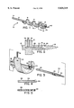
- FIG. 1 is substantially a perspective view of the present invention.
- FIG. 2 is substantially a sectional view taken at 2--2 of FIG. 1.
- FIG. 3 is substantially a plan view for assembly of the present invention.
- FIG. 4 is substantially a side view showing a second embodiment for the shank of the bit.
- FIG. 5 is substantially a side view showing a third embodiment for the shank of the bit.
- arrow (10) is substantially an overview of the present invention which is substantially an auger bit having a removably attached replaceable tapered screw type biting tip.
- the bit (10) comprises an axially elongated shank (12) having at least one integrally formed spiral channel (14) protruding therefrom which forms a cutting edge (15) and the shank (12) having a first end (16) which is removably attachable to an auger tool and a second end (18) which is of a shape and size to removably receive a replaceable tapered screw type biting tip therein (represented by arrow 20) and removable fastener means (later described) for retaining the tip (20) within the second end (18), with the bit (10) and the replaceable tip (20) being made from any suitable material of choice, such as metal, steel, etc.
- the shank (12) of bit (10) further includes an elongated circular cavity (22) extending partially into the shank along a central axis longitudinally through the shank (12) from the second end (18) with the circular cavity (22) opening into substantially a rectangular shaped recess (24) on the second end (18), as more clearly shown within FIG. 2.
- the tip (arrow 20) substantially comprises an elongated circular shaft (26) integrally attached to substantially a rectangular shaped stop means (28) which is integrally attached to a tapered screw type biting tip portion (30) (as clearly shown within FIG. 3) and the circular shaft (26) being of a shape and size to be slidably inserted within the circular cavity (22) and the stop means (28) being of a shape and size to be slidably inserted into the recess (24).
- the circular cavity (22) is of a shape and size to receive various shafts therein.
- the tapered screw type biting tip portion (30) may have various biting channels of choice, such as a six channeled biting tip portion is shown within FIGS. 1 & 2, while a ten channeled biting tip portion is shown within FIG. 3.
- the elongated circular cavity (22) may be threaded and extends partially into the shank (12) along a central axis longitudinally through the shank (12) from the second end (18) and forms substantially an external circular opening (23) on the second end (18), this allows the elongated circular threaded shaft (26) of FIG. 5 (which is integrally attached to the tapered screw type biting tip 30) to be threadably removably engaged within cavity (22).
- fastener means of engineering choice for retaining the shaft (26) of tip (20) within the circular cavity (22) may be used.
- the fastener means (which may be substantially located at a position of engineering choice upon the second end 18 of the shaft 12) being positioned within one of the channels (14).
- the fastener means being substantially a threaded vertical bore (34) partially through the second end (18) which is in open communication with the cavity (22) for receiving a threaded screw (36) and when the screw (36) is threadably engaged within the bore (34) the screw removably retains the shaft (26) within the cavity (22).
- Further fastening means may include if so desired an indent (38) (shown within FIG. 4) which is of a size and shape to partially receive the threaded end of screw (36) therein and the indent may be aligned with the stop means (28).
- a spiral type auger bit having a tool engaging portion at one end, and the second end thereof being of a shape and size to removably receive a replaceable tip therein.
- spiral type auger bit which may be sold and/or manufactured as a kit including various types of replaceable tips therewith.
Landscapes
- Life Sciences & Earth Sciences (AREA)
- Engineering & Computer Science (AREA)
- Mechanical Engineering (AREA)
- Wood Science & Technology (AREA)
- Forests & Forestry (AREA)
- Earth Drilling (AREA)
Abstract
The present invention is substantially a spiral type auger bit having a first end which is removably attachable to an auger tool and a second end which is of a shape and size to removably receive a replaceable tapered screw type biting tip therein.
Description
The present invention is substantially related to spiral type bits but more particularly relates to a spiral type auger bit having a first end which is removably attachable to an auger tool and a second end which is of a shape and size to removably receive a replaceable tip therein.
Many aspects of the building construction industry involve installation of various means for providing services such as wiring plumbing, and pipe fitting. These various installations, as well as others, involve attaching or routing such means through the structural components of a building. In this trade, it is well known to use various sized spiral type auger bits, with each being used for various purposes.
The typical auger bit (such as taught within U.S. Pat. Nos. 5,244,319 and 877,831) has a tool engaging portion at one end and a head portion containing an integrally formed drill tip on the second end. Unfortunately, these bits are very costly and must be replaced often due to the fact that the drill tips wear out, even though the actual integrally formed bit and shank portions remain functional. Again, this practice of continually buying a new bit when the drill tip wears out, can be extremely costly for the workman who incurs such cost. It is therefore contended by the applicants, that if the workman could simply replace the worn out drill tip with a new one rather than replace the entire bit, this would be highly advantageous for the workman and save them considerable costs.
Within the prior art, replaceable drill tips have been taught, such as U.S. Pat. No. 4,950,108 teaches a drill for metal working comprising a drill body and a replaceable tip. This reference is functional for its intended use, but due to the design of the fastener means which retains the replaceable tip, it could not be used to replace the drill tip of an auger bit.
It is therefore contended by the applicants that a need exists for an auger bit which allows the workman to replace the biting tip thereof, when the tip has become worn.
It is therefore an object of the present invention to provide substantially a spiral type auger bit having a tool engaging portion at one end, and the second end thereof being of a shape and size to removably receive a replaceable tapered screw type biting tip therein.
It is a further object of the present invention is to provide a spiral type auger bit which includes means to removably retain therein various types of biting tips of choice, with each having a specific design and purpose.
Still a further object of the present invention is to provide a spiral type auger bit which may be sold and manufactured as a complete kit, having the above noted replaceable tips therewith.
Yet another object of the present invention is to provide a spiral type auger bit having a replaceable tip which can be manufactured and produced in various sizes of choice.
Still another object of the present invention is to provide a spiral type auger bit having a replaceable tip which includes all of the advantages as taught within the typical prior art and eliminates their inherent drawbacks.
FIG. 1 is substantially a perspective view of the present invention.
FIG. 2 is substantially a sectional view taken at 2--2 of FIG. 1.
FIG. 3 is substantially a plan view for assembly of the present invention.
FIG. 4 is substantially a side view showing a second embodiment for the shank of the bit.
FIG. 5 is substantially a side view showing a third embodiment for the shank of the bit.
Referring now to the drawings wherein like characters refer to like elements throughout the various views. In FIG. 1, arrow (10) is substantially an overview of the present invention which is substantially an auger bit having a removably attached replaceable tapered screw type biting tip. The bit (10) comprises an axially elongated shank (12) having at least one integrally formed spiral channel (14) protruding therefrom which forms a cutting edge (15) and the shank (12) having a first end (16) which is removably attachable to an auger tool and a second end (18) which is of a shape and size to removably receive a replaceable tapered screw type biting tip therein (represented by arrow 20) and removable fastener means (later described) for retaining the tip (20) within the second end (18), with the bit (10) and the replaceable tip (20) being made from any suitable material of choice, such as metal, steel, etc.
The shank (12) of bit (10) further includes an elongated circular cavity (22) extending partially into the shank along a central axis longitudinally through the shank (12) from the second end (18) with the circular cavity (22) opening into substantially a rectangular shaped recess (24) on the second end (18), as more clearly shown within FIG. 2.
The tip (arrow 20) substantially comprises an elongated circular shaft (26) integrally attached to substantially a rectangular shaped stop means (28) which is integrally attached to a tapered screw type biting tip portion (30) (as clearly shown within FIG. 3) and the circular shaft (26) being of a shape and size to be slidably inserted within the circular cavity (22) and the stop means (28) being of a shape and size to be slidably inserted into the recess (24).
Clearly shown within FIGS. 3, 4 & 5, we provide various types of shafts (26) for the tip, (tip represented by arrow 20) thus the circular cavity (22) is of a shape and size to receive various shafts therein.
It is to be noted that if so desired, the tapered screw type biting tip portion (30) may have various biting channels of choice, such as a six channeled biting tip portion is shown within FIGS. 1 & 2, while a ten channeled biting tip portion is shown within FIG. 3.
It is to be further noted that if so desired, the elongated circular cavity (22) may be threaded and extends partially into the shank (12) along a central axis longitudinally through the shank (12) from the second end (18) and forms substantially an external circular opening (23) on the second end (18), this allows the elongated circular threaded shaft (26) of FIG. 5 (which is integrally attached to the tapered screw type biting tip 30) to be threadably removably engaged within cavity (22).
Various fastener means of engineering choice for retaining the shaft (26) of tip (20) within the circular cavity (22) may be used. For example we have shown within FIG. 2, the fastener means (which may be substantially located at a position of engineering choice upon the second end 18 of the shaft 12) being positioned within one of the channels (14). The fastener means being substantially a threaded vertical bore (34) partially through the second end (18) which is in open communication with the cavity (22) for receiving a threaded screw (36) and when the screw (36) is threadably engaged within the bore (34) the screw removably retains the shaft (26) within the cavity (22). Further fastening means may include if so desired an indent (38) (shown within FIG. 4) which is of a size and shape to partially receive the threaded end of screw (36) therein and the indent may be aligned with the stop means (28).
It will now be seen that we have herein provided an auger bit which allows the workman to replace the drill tip thereof when so desired.
It will also be seen that we have herein provided a spiral type auger bit having a tool engaging portion at one end, and the second end thereof being of a shape and size to removably receive a replaceable tip therein.
It will further be seen that we have herein provided a spiral type auger bit which removably accepts various types of drill tips of choice therein.
It will also be seen that we have herein provided a spiral type auger bit which may be sold and/or manufactured as a kit including various types of replaceable tips therewith.
Although the invention has been shown and described in what is conceived to be the most practical and preferred embodiment it is recognized that departures may be made therefrom within the scope and spirit of the invention, which is not to be limited to the details disclosed herein but is to be accorded the full scope of the claims so as to embrace any and all equivalent devices and or apparatus's.
Claims (1)
1. An auger bit comprising: an axially elongated shank having at least one integrally formed spiral channel protruding therefrom which forms a cutting edge, said shank having a first end which is removably attachable to an auger tool and a second end which is of a shape and size to removably receive a replaceable tip therein, said shank having an elongated circular cavity extending partially into said shank along a central axis longitudinally through said shank from said second end, and said cavity opening into substantially a rectangular shaped recess on said second end, a fastener means being substantially a threaded vertical bore partially through said second end which is in open communication with said cavity for receiving a threaded screw, said replaceable tip comprising: substantially an elongated circular shaft integrally attached to a rectangular shaped stop means which is integrally attached to a tapered screw type biting tip portion, said circular shaft being of a shape and size to be slidably inserted within said circular cavity, said stop means being of a shape and size to be slidably inserted into said recess, and said screw when threadably engaged within said bore, removably retains said shaft within said cavity.
Priority Applications (1)
| Application Number | Priority Date | Filing Date | Title |
|---|---|---|---|
| US08/586,001 US5820319A (en) | 1996-01-16 | 1996-01-16 | Auger bit having a replaceable tip |
Applications Claiming Priority (1)
| Application Number | Priority Date | Filing Date | Title |
|---|---|---|---|
| US08/586,001 US5820319A (en) | 1996-01-16 | 1996-01-16 | Auger bit having a replaceable tip |
Publications (1)
| Publication Number | Publication Date |
|---|---|
| US5820319A true US5820319A (en) | 1998-10-13 |
Family
ID=24343877
Family Applications (1)
| Application Number | Title | Priority Date | Filing Date |
|---|---|---|---|
| US08/586,001 Expired - Fee Related US5820319A (en) | 1996-01-16 | 1996-01-16 | Auger bit having a replaceable tip |
Country Status (1)
| Country | Link |
|---|---|
| US (1) | US5820319A (en) |
Cited By (33)
| Publication number | Priority date | Publication date | Assignee | Title |
|---|---|---|---|---|
| US6612788B2 (en) * | 2001-03-30 | 2003-09-02 | Black & Decker Inc. | Self-feed wood bit |
| US6652202B2 (en) | 2000-01-03 | 2003-11-25 | Quick Turn Manufacturing, Llc | Drill bit apparatus and method of manufacture of same |
| US20040052595A1 (en) * | 2002-09-18 | 2004-03-18 | Dembicks Tyler J. | Drill bit point storage system |
| US20050249563A1 (en) * | 2004-05-04 | 2005-11-10 | Scott Gary F | Wood boring bit with increased speed, efficiency and ease of use |
| US20060013668A1 (en) * | 2002-11-25 | 2006-01-19 | Urs Fankhauser | Anchor bar with a support block |
| US20070280798A1 (en) * | 2006-03-02 | 2007-12-06 | Zeiler Jeffrey M | Cutting tool |
| US20080138165A1 (en) * | 2006-12-06 | 2008-06-12 | Laverne Durfee | Drill bit |
| US20080166194A1 (en) * | 2007-01-09 | 2008-07-10 | Durfee Laverne R | Drill bit |
| US20080193236A1 (en) * | 2007-02-13 | 2008-08-14 | Durfee Laverne R | Drill bit screw tip |
| US20080298916A1 (en) * | 2005-10-08 | 2008-12-04 | Kenneth Jordan | Replaceable tip for a bit or auger bit |
| US20080313876A1 (en) * | 2005-07-23 | 2008-12-25 | Mark Vincent | Extraction Device for Use When Extracting a Ceramic Foam Filter |
| US20090087273A1 (en) * | 2006-03-02 | 2009-04-02 | Douglas Allen | Cutting tool |
| US20090208302A1 (en) * | 2008-02-19 | 2009-08-20 | Irwin Industrial Tool Company | Multi-blade self feed bit |
| US20090208300A1 (en) * | 2008-02-19 | 2009-08-20 | Irwin Industrial Tool Company | Self feed bit |
| US20100003094A1 (en) * | 2007-01-09 | 2010-01-07 | Irwin Industrial Tool Company | Drill bit |
| WO2010025192A1 (en) * | 2008-08-26 | 2010-03-04 | Ison Orlo D | Auger bit with a removable tip |
| US20100124467A1 (en) * | 2008-11-19 | 2010-05-20 | William Nordlin | Auger bit with interlocking feed screw and cutting insert |
| US20100307640A1 (en) * | 2009-06-03 | 2010-12-09 | Durfee La Verne R | Cutting edge and cutting tool |
| US20120063859A1 (en) * | 2010-09-09 | 2012-03-15 | Robert Bosch Tool Corporation | Drill Bit |
| US9163382B2 (en) | 2013-01-16 | 2015-10-20 | King Kutter, Inc. | Gearbox lock mechanism |
| US9500038B2 (en) | 2013-02-01 | 2016-11-22 | Milwaukee Electric Tool Corporation | Auger bit with replaceable cutting bit |
| US9834999B2 (en) | 2011-07-13 | 2017-12-05 | King Kutter, Inc. | Post hole digger |
| US20190091070A1 (en) * | 2013-12-03 | 2019-03-28 | Earways Medical Ltd. | Ear wax removal device and methods thereof |
| USD859483S1 (en) * | 2016-12-06 | 2019-09-10 | Milwaukee Electric Tool Corporation | Drill bit |
| USD872783S1 (en) * | 2018-04-27 | 2020-01-14 | Milwaukee Electric Tool Corporation | Step drill bit |
| USD942517S1 (en) * | 2021-02-07 | 2022-02-01 | Jun Li | Auger drill bit |
| USD943650S1 (en) * | 2021-02-05 | 2022-02-15 | Xinwei Li | Auger drill bit |
| USD944301S1 (en) * | 2021-02-07 | 2022-02-22 | Jun Li | Auger drill bit |
| US11285632B2 (en) | 2018-03-21 | 2022-03-29 | Milwaukee Electric Tool Corporation | Auger |
| US11304850B2 (en) | 2017-03-24 | 2022-04-19 | Earways Medical Ltd. | Apparatus and method for treating or/and refreshing an ear canal |
| US11324635B2 (en) | 2012-06-14 | 2022-05-10 | Earways Medical Ltd. | Cerumen removal apparatus |
| USD973735S1 (en) * | 2020-03-04 | 2022-12-27 | Milwaukee Electric Tool Corporation | Drill bit |
| US11692578B2 (en) | 2018-09-26 | 2023-07-04 | Illinois Tool Works Inc. | Post-to-beam fastener |
Citations (14)
| Publication number | Priority date | Publication date | Assignee | Title |
|---|---|---|---|---|
| DE197809C (en) * | ||||
| US21179A (en) * | 1858-08-17 | The cutters to the spindles of augers | ||
| US166378A (en) * | 1875-08-03 | Improvement in augers | ||
| US716557A (en) * | 1902-09-03 | 1902-12-23 | Seward R Seybold | Tubular auger. |
| US778845A (en) * | 1903-07-14 | 1905-01-03 | Edward Thomas Cox | Wood-boring auger. |
| US877831A (en) * | 1907-03-04 | 1908-01-28 | Patrick J Creedon | Auger-bit. |
| US1389578A (en) * | 1920-10-18 | 1921-09-06 | Harry Mairus | Auger |
| US2883888A (en) * | 1951-08-17 | 1959-04-28 | Arthur H Stewart | Boring tool and method for making same |
| US3426860A (en) * | 1966-12-27 | 1969-02-11 | Gerald A Petersen | Pilot bit with replaceable teeth |
| US3687565A (en) * | 1971-03-01 | 1972-08-29 | John E Byers | Drill bit device |
| US4625593A (en) * | 1984-08-07 | 1986-12-02 | Schmotzer Norman H | Wood drill and method of construction |
| US5092719A (en) * | 1987-06-29 | 1992-03-03 | Attila Zsiger | Auger bit |
| US5143163A (en) * | 1991-08-29 | 1992-09-01 | Kennametal Inc. | Digging tooth |
| US5244319A (en) * | 1991-11-01 | 1993-09-14 | Greenlee Textron Inc. | Auger bit |
-
1996
- 1996-01-16 US US08/586,001 patent/US5820319A/en not_active Expired - Fee Related
Patent Citations (14)
| Publication number | Priority date | Publication date | Assignee | Title |
|---|---|---|---|---|
| DE197809C (en) * | ||||
| US21179A (en) * | 1858-08-17 | The cutters to the spindles of augers | ||
| US166378A (en) * | 1875-08-03 | Improvement in augers | ||
| US716557A (en) * | 1902-09-03 | 1902-12-23 | Seward R Seybold | Tubular auger. |
| US778845A (en) * | 1903-07-14 | 1905-01-03 | Edward Thomas Cox | Wood-boring auger. |
| US877831A (en) * | 1907-03-04 | 1908-01-28 | Patrick J Creedon | Auger-bit. |
| US1389578A (en) * | 1920-10-18 | 1921-09-06 | Harry Mairus | Auger |
| US2883888A (en) * | 1951-08-17 | 1959-04-28 | Arthur H Stewart | Boring tool and method for making same |
| US3426860A (en) * | 1966-12-27 | 1969-02-11 | Gerald A Petersen | Pilot bit with replaceable teeth |
| US3687565A (en) * | 1971-03-01 | 1972-08-29 | John E Byers | Drill bit device |
| US4625593A (en) * | 1984-08-07 | 1986-12-02 | Schmotzer Norman H | Wood drill and method of construction |
| US5092719A (en) * | 1987-06-29 | 1992-03-03 | Attila Zsiger | Auger bit |
| US5143163A (en) * | 1991-08-29 | 1992-09-01 | Kennametal Inc. | Digging tooth |
| US5244319A (en) * | 1991-11-01 | 1993-09-14 | Greenlee Textron Inc. | Auger bit |
Cited By (61)
| Publication number | Priority date | Publication date | Assignee | Title |
|---|---|---|---|---|
| US6652202B2 (en) | 2000-01-03 | 2003-11-25 | Quick Turn Manufacturing, Llc | Drill bit apparatus and method of manufacture of same |
| US6612788B2 (en) * | 2001-03-30 | 2003-09-02 | Black & Decker Inc. | Self-feed wood bit |
| US20040052595A1 (en) * | 2002-09-18 | 2004-03-18 | Dembicks Tyler J. | Drill bit point storage system |
| US7726923B2 (en) * | 2002-11-25 | 2010-06-01 | Ed. Geistlich & Söhne AG | Anchor bar with a support block |
| US20060013668A1 (en) * | 2002-11-25 | 2006-01-19 | Urs Fankhauser | Anchor bar with a support block |
| US20050249563A1 (en) * | 2004-05-04 | 2005-11-10 | Scott Gary F | Wood boring bit with increased speed, efficiency and ease of use |
| US7416371B2 (en) * | 2004-05-04 | 2008-08-26 | Irwin Industrial Tool Company | Wood boring bit with increased speed, efficiency and ease of use |
| US8112864B2 (en) | 2005-07-23 | 2012-02-14 | Pyrotek, Inc. | Extraction device for use when extracting a ceramic foam filter |
| US20080313876A1 (en) * | 2005-07-23 | 2008-12-25 | Mark Vincent | Extraction Device for Use When Extracting a Ceramic Foam Filter |
| US8109700B2 (en) | 2005-10-08 | 2012-02-07 | Milwaukee Electric Tool Corporation | Replaceable tip for a bit or auger bit |
| US20110188955A1 (en) * | 2005-10-08 | 2011-08-04 | Kenneth Jordan | Replaceable tip for a bit or auger bit |
| US7909547B2 (en) * | 2005-10-08 | 2011-03-22 | Milwaukee Electric Tool Corporation | Replaceable tip for a bit or auger bit |
| US20080298916A1 (en) * | 2005-10-08 | 2008-12-04 | Kenneth Jordan | Replaceable tip for a bit or auger bit |
| US20070280798A1 (en) * | 2006-03-02 | 2007-12-06 | Zeiler Jeffrey M | Cutting tool |
| US20100322733A1 (en) * | 2006-03-02 | 2010-12-23 | Douglas Allen | Cutting tool |
| US10618119B2 (en) | 2006-03-02 | 2020-04-14 | Milwaukee Electric Tool Corporation | Cutting tool |
| US9339874B2 (en) | 2006-03-02 | 2016-05-17 | Milwaukee Electric Tool Corporation | Cutting tool |
| US7625160B2 (en) | 2006-03-02 | 2009-12-01 | Milwaukee Electric Tool Corporation | Cutting tool |
| US20090087273A1 (en) * | 2006-03-02 | 2009-04-02 | Douglas Allen | Cutting tool |
| US7661911B2 (en) | 2006-03-02 | 2010-02-16 | Milwaukee Electric Tool Corporation | Cutting tool |
| US8371777B2 (en) | 2006-03-02 | 2013-02-12 | Milwaukee Electric Tool Corporation | Cutting tool |
| US8328477B2 (en) | 2006-03-02 | 2012-12-11 | Milwaukee Electric Tool Corporation | Cutting tool |
| US20070277656A1 (en) * | 2006-03-02 | 2007-12-06 | Zeiler Jeffrey M | Cutting tool |
| US20080138165A1 (en) * | 2006-12-06 | 2008-06-12 | Laverne Durfee | Drill bit |
| US20100003094A1 (en) * | 2007-01-09 | 2010-01-07 | Irwin Industrial Tool Company | Drill bit |
| US20080166194A1 (en) * | 2007-01-09 | 2008-07-10 | Durfee Laverne R | Drill bit |
| US7544026B2 (en) | 2007-02-13 | 2009-06-09 | Irwin Industrial Tool Company | Drill bit screw tip |
| US20080193236A1 (en) * | 2007-02-13 | 2008-08-14 | Durfee Laverne R | Drill bit screw tip |
| US8070397B2 (en) | 2008-02-19 | 2011-12-06 | Irwin Industrial Tool Company | Self feed bit |
| US20090208302A1 (en) * | 2008-02-19 | 2009-08-20 | Irwin Industrial Tool Company | Multi-blade self feed bit |
| US8070398B2 (en) | 2008-02-19 | 2011-12-06 | Irwin Industrial Tool Company | Multi-blade self feed bit |
| US20090208300A1 (en) * | 2008-02-19 | 2009-08-20 | Irwin Industrial Tool Company | Self feed bit |
| WO2010025192A1 (en) * | 2008-08-26 | 2010-03-04 | Ison Orlo D | Auger bit with a removable tip |
| DE102009044402A1 (en) | 2008-11-19 | 2010-07-15 | Greenlee Textron Inc., Rockford | Bar drill with engaging feed screw and cutting insert |
| US20100124467A1 (en) * | 2008-11-19 | 2010-05-20 | William Nordlin | Auger bit with interlocking feed screw and cutting insert |
| US8057135B2 (en) | 2008-11-19 | 2011-11-15 | Greenlee Textron Inc. | Auger bit with interlocking feed screw and cutting insert |
| US20100307640A1 (en) * | 2009-06-03 | 2010-12-09 | Durfee La Verne R | Cutting edge and cutting tool |
| US20120063859A1 (en) * | 2010-09-09 | 2012-03-15 | Robert Bosch Tool Corporation | Drill Bit |
| US8784017B2 (en) * | 2010-09-09 | 2014-07-22 | Robert Bosch Gmbh | Drill bit |
| US9834999B2 (en) | 2011-07-13 | 2017-12-05 | King Kutter, Inc. | Post hole digger |
| US11324635B2 (en) | 2012-06-14 | 2022-05-10 | Earways Medical Ltd. | Cerumen removal apparatus |
| US9163382B2 (en) | 2013-01-16 | 2015-10-20 | King Kutter, Inc. | Gearbox lock mechanism |
| US9500038B2 (en) | 2013-02-01 | 2016-11-22 | Milwaukee Electric Tool Corporation | Auger bit with replaceable cutting bit |
| US20190091070A1 (en) * | 2013-12-03 | 2019-03-28 | Earways Medical Ltd. | Ear wax removal device and methods thereof |
| US11432964B2 (en) * | 2013-12-03 | 2022-09-06 | Earways Medical Ltd. | Ear wax removal device and methods thereof |
| USD1007546S1 (en) | 2016-12-06 | 2023-12-12 | Milwaukee Electric Tool Corporation | Drill bit |
| USD859483S1 (en) * | 2016-12-06 | 2019-09-10 | Milwaukee Electric Tool Corporation | Drill bit |
| USD923674S1 (en) * | 2016-12-06 | 2021-06-29 | Milwaukee Electric Tool Corporation | Drill bit |
| US11304850B2 (en) | 2017-03-24 | 2022-04-19 | Earways Medical Ltd. | Apparatus and method for treating or/and refreshing an ear canal |
| US11285632B2 (en) | 2018-03-21 | 2022-03-29 | Milwaukee Electric Tool Corporation | Auger |
| US11850767B2 (en) | 2018-03-21 | 2023-12-26 | Milwaukee Electric Tool Corporation | Auger |
| USD892183S1 (en) * | 2018-04-27 | 2020-08-04 | Milwaukee Electric Tool Corporation | Step drill bit |
| USD881241S1 (en) * | 2018-04-27 | 2020-04-14 | Milwaukee Electric Tool Corporation | Step drill bit |
| USD872783S1 (en) * | 2018-04-27 | 2020-01-14 | Milwaukee Electric Tool Corporation | Step drill bit |
| US11692578B2 (en) | 2018-09-26 | 2023-07-04 | Illinois Tool Works Inc. | Post-to-beam fastener |
| USD973735S1 (en) * | 2020-03-04 | 2022-12-27 | Milwaukee Electric Tool Corporation | Drill bit |
| USD1004648S1 (en) | 2020-03-04 | 2023-11-14 | Milwaukee Electric Tool Corporation | Drill bit |
| USD1025153S1 (en) | 2020-03-04 | 2024-04-30 | Milwaukee Electric Tool Corporation | Drill bit |
| USD943650S1 (en) * | 2021-02-05 | 2022-02-15 | Xinwei Li | Auger drill bit |
| USD944301S1 (en) * | 2021-02-07 | 2022-02-22 | Jun Li | Auger drill bit |
| USD942517S1 (en) * | 2021-02-07 | 2022-02-01 | Jun Li | Auger drill bit |
Similar Documents
| Publication | Publication Date | Title |
|---|---|---|
| US5820319A (en) | Auger bit having a replaceable tip | |
| DE3027408C2 (en) | Drilling device for producing drill holes with undercuts | |
| US5326196A (en) | Pilot drill bit | |
| JPH0232397Y2 (en) | ||
| EP0578275A1 (en) | Self-drilling blind rivet | |
| AU739764B2 (en) | Drilling and fastener driving tool | |
| US6286400B1 (en) | Electrical installer putty-filled screw hole clearing 10-in-1 driving tool | |
| DE4132228A1 (en) | DRILLING DEVICE FOR PRODUCING DRILL HOLES WITH UNDERCUT | |
| EP0941793A3 (en) | Drilling tool | |
| EP0481220A2 (en) | Clamping chuck | |
| EP0474591B1 (en) | Subcalibre shaft with central drillholder | |
| CA2160043C (en) | Drilling unit with hollow annular drill bit and central drill | |
| US9212553B2 (en) | Dirt and rock cutting bit tool | |
| EP0302202A2 (en) | Device for attaching fasteners | |
| DE3004077A1 (en) | DRILL BIT | |
| US5219250A (en) | Cutting tool for plasterboard | |
| HU223127B1 (en) | Rock drill | |
| DE102006006445A1 (en) | Tool for boring hole of diameter of more than fifty millimeter, into workpiece, has hollow cylindrical tool support in sections, where workpiece is arranged at assigned end of tool blade | |
| DE3015999C2 (en) | Drilling unit for producing an undercut in the borehole | |
| EP2345496A1 (en) | Tool holder | |
| NZ202940A (en) | Power tool attachment:adaptor fits over drill bit | |
| DE2826413A1 (en) | Hand drill guide for hole cutting - has clamp for drill on crank, parallel to pin in hole | |
| CA2904314A1 (en) | Drill bit system and method for forming holes in materials | |
| EP1214179B1 (en) | Hole-forming tool | |
| US4157879A (en) | Pipe reaming tool |
Legal Events
| Date | Code | Title | Description |
|---|---|---|---|
| REMI | Maintenance fee reminder mailed | ||
| LAPS | Lapse for failure to pay maintenance fees | ||
| STCH | Information on status: patent discontinuation |
Free format text: PATENT EXPIRED DUE TO NONPAYMENT OF MAINTENANCE FEES UNDER 37 CFR 1.362 |
|
| FP | Lapsed due to failure to pay maintenance fee |
Effective date: 20021013 |