US5755108A - Wedge type refrigerated display case - Google Patents
Wedge type refrigerated display case Download PDFInfo
- Publication number
- US5755108A US5755108A US08/759,173 US75917396A US5755108A US 5755108 A US5755108 A US 5755108A US 75917396 A US75917396 A US 75917396A US 5755108 A US5755108 A US 5755108A
- Authority
- US
- United States
- Prior art keywords
- air
- coil
- channel
- case
- outlet
- Prior art date
- Legal status (The legal status is an assumption and is not a legal conclusion. Google has not performed a legal analysis and makes no representation as to the accuracy of the status listed.)
- Expired - Lifetime
Links
Images


Classifications
-
- A—HUMAN NECESSITIES
- A47—FURNITURE; DOMESTIC ARTICLES OR APPLIANCES; COFFEE MILLS; SPICE MILLS; SUCTION CLEANERS IN GENERAL
- A47F—SPECIAL FURNITURE, FITTINGS, OR ACCESSORIES FOR SHOPS, STOREHOUSES, BARS, RESTAURANTS OR THE LIKE; PAYING COUNTERS
- A47F3/00—Show cases or show cabinets
- A47F3/04—Show cases or show cabinets air-conditioned, refrigerated
- A47F3/0404—Cases or cabinets of the closed type
- A47F3/0408—Cases or cabinets of the closed type with forced air circulation
-
- A—HUMAN NECESSITIES
- A47—FURNITURE; DOMESTIC ARTICLES OR APPLIANCES; COFFEE MILLS; SPICE MILLS; SUCTION CLEANERS IN GENERAL
- A47F—SPECIAL FURNITURE, FITTINGS, OR ACCESSORIES FOR SHOPS, STOREHOUSES, BARS, RESTAURANTS OR THE LIKE; PAYING COUNTERS
- A47F3/00—Show cases or show cabinets
- A47F3/04—Show cases or show cabinets air-conditioned, refrigerated
- A47F3/0439—Cases or cabinets of the open type
- A47F3/0443—Cases or cabinets of the open type with forced air circulation
Definitions
- This invention relates to refrigerated display cases, and particularly to refrigerated display cases with unusual configurations such as a wedge shape, resulting in restricted return air flow conduit space at the rear of the case.
- refrigerated display cases of the open front or glass door front types utilize recirculating refrigerated air that traverses the lower evaporative coil and then is propelled up through the rear duct in the back of the case to the top, from where it flows downwardly across the front to the return duct for recirculation to the coil.
- the rear duct extends the full width of the case behind the storage shelves, thereby providing considerably ample conduit space for air flow back to the top.
- This invention presents a new type of display case assembly resulting in proper refrigeration for display case wedges, as well as other shapes such as circular or polygonal shaped cylinders.
- An object of this invention is to provide unusually shaped refrigerated display cases with special refrigerated air flow features effecting proper performance for the case.
- a narrow case back resulting in restricted air flow through the return duct might exit, this air flow is complemented by special air flow facilities in the shelf area of the display case.
- This special air flow resulting preferably from air moving directly through the lowermost shelf at the rear thereof, and/or through outlets at the rear wall to flow over the shelves, preferably by use of a special second rear duct and vents through the rear wall panel, achieves a combination of air flow characteristics resulting in effective and efficient performance of the case.
- FIG. 1 is a schematic view of a multipart refrigerated display case assembly employing two conventional elongated display cases adjacent a corner, and a novel wedge shaped display case at the corner;
- FIG. 2 is an enlarged cross sectional view of the lower part of the wedge shaped display case in FIG. 1;
- FIG. 3 is a side elevational sectional view of a first embodiment of an open front wedge type display case according to this invention.
- FIG. 4 is a side elevational sectional view of a glass front refrigerated display case employing the first embodiment of this invention
- FIG. 5 is a side elevational sectional view of a second embodiment of open front display case employing this invention.
- FIG. 6 is a side elevational sectional view of the glass door type employing the second embodiment of this invention.
- FIG. 7 is a side elevational sectional view of an open front display case employing a third embodiment of this invention.
- FIG. 8 is a perspective view of a cylindrically configurated display case with a circular cross section
- FIG. 9 is a top plan view of the display case in FIG. 8;
- FIG. 10 is a top plan view of an alternative cylindrical configuration with a polygonal cross section according to the invention herein.
- FIG. 1 of the drawings the schematic diagram illustrates an arrangement where a pair of refrigerated display cases 12 and 14 are adjacent an interior corner of a store or super market, leaving a space therebetween.
- a wedge-shaped refrigerated display case 10 according to this invention is located in that space.
- a cross section of the bottom portion of that wedge-shaped case is depicted in FIG. 2.
- This case includes a pair of back walls 16 which converge and meet at the rearmost portion of the case.
- the widest portion of the case is an access 18 which can be an open front or a door type reach-in assembly of conventional type.
- a refrigeration evaporator coil 20 of conventional type, through which the recirculated air passes in order to cool it.
- the evaporator coil has an air inlet to receive air from the display case, and an air outlet which communicates with a restricted passage or channel 22 at the rear of the case, for vertical flow of the cooled air from the bottom of the case up to the top of the case. Air is propelled through coil 20 by one or more fans 24 adjacent the coil.
- FIGS. 3 and 4 show the first embodiment of this wedge case, FIG. 3 showing an open front type and FIG. 4 showing a glass door reach-in type;
- FIGS. 5 and 6 show a second embodiment of the wedge-type case, FIG. 5 showing an open front type and FIG. 6 showing a glass door reach-in type;
- FIG. 7 shows a third embodiment of the wedge case.
- the display case includes a bottom 30, a top 32, a back 16, a display space 36 having at least one, and here shown to be two, display shelves 38 and 40 mounted in cantilever fashion at the back wall panel 42.
- the refrigeration evaporator coil 20 with an air inlet 44 to the coil, an air outlet 46 from the coil, and at least one fan 24 adjacent the coil for propelling air therethrough.
- Outlet 46 from the coil communicates with the upward channel 22 between back panel 42 of the display space and back wall 16.
- Channel 22 extends upwardly from the bottom of the case to the top thereof and across to the front of the case to an air outlet discharge 48 oriented downwardly in front of the case toward the inlet 44.
- Outlet 48 may have suitable air directing honeycomb or the like therein in conventional fashion.
- At least one fan 50 is mounted at the top of the case for drawing air up channel 22 and propelling it across the top and through opening 48.
- the air flowing down in front of the shelves 38 and 40 forms an air curtain in the case of FIG. 3 to pneumatically separate the display space 36 from the ambient atmosphere.
- Above the coil is an area typically called the well 52, which is the space beneath the bottommost shelf 40 in the display space.
- Outlet 46 from the coil also communicates with an opening 54 to the well 52.
- bottom shelf 40 includes at the rear portion thereof an orifice 55 through the shelf to allow air to flow from the well 52 through shelf 40 to the space above the shelf and over the shelf to the front for flow back to the inlet 44.
- the display case is similar to that in FIG. 3 except that the front access includes openable doors 18 at the access for reach-in to the display space 36. Otherwise the case is like that in FIG. 3, including a top 32, a bottom 30, evaporator coil 20, air inlet 44, fan 24, air outlet 46, restricted vertical channel 22 leading to the portion of the channel across the top, fan 50 and discharge 48.
- the shelves 38 and 40 are above one another, the bottom shelf 40 showing an orifice 55 for air flow from the well 52 up through shelf 40. Opening 54 allows air flow from the outlet 46 down in front of the shelves to the well 52 and inlet 44.
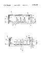
- the second embodiment depicted in FIGS. 5 and 6 differs somewhat from the first embodiment in FIGS. 3 and 4 by including a pair of vertical channels at the rear of the case. More specifically, referring to FIG. 5, there is shown not only the restricted vertical channel 22 from outlet 46 up to the top of the case and fan 50, but also a second vertical channel 23 immediately adjacent the back panel 42. This embodiment also illustrates a plurality of four shelves above the well area 52. Above each shelf in back panel 42 are vents 25 to allow air to flow from channel 23 to the display space 36 above each shelf and over each shelf to the front of the case where the air curtain flowing down from outlet 48 through the air inlet 44 will entrain this air flow and cause it to recirculate.
- air entering at inlet 44 and propelled by fan 24 through the evaporator coil 20 to outlet 46 not only flows up vertical restricted channel 22 as drawn by fan 50 and across the top of the case to outlet 48 for discharge of the air down the front access, but also air from outlet 46 is propelled up channel 23 and through the vent 25 above the shelves 140, 138, etc. to join the air flowing down in front of the shelves and thereby cooperate with the other portions of recirculating air for efficient and effective functioning of the case.
- FIG. 6 has many similarities to that in FIG. 5, but includes a front door assembly 18 for reach-in access. It also includes the channel 23 as well as 22.
- the structure is here shown to include a plurality of three shelves, with back wall vents 25 above each shelf for air flow over the shelf and forwardly thereof to be entrained by the downwardly moving air from outlet 48 of channel 22. This downwardly flowing air moves into the inlet 44 to the evaporator coil 20 as drawn by fan 24, the air through the coil then exiting at outlet 46 for discharge into both channels 22 and 23. Air in channel 22 is drawn upwardly by fan 50.
- FIG. 7 differs from that in FIGS. 3 and 5 in that it combines certain features of those in the first and second embodiments.
- this display case in FIG. 7 includes not only the channel 23 as well as the restricted channel 22 and vents 25 above the respective shelves, two of which are here shown, but also the outlet 46 from the refrigerator coil 20 communicates not only with channel 22 and channel 23, but also with an orifice 54 to the well area 52 above the coil, for refrigerated air flow through opening 54 to the well area and through orifice 55 in shelf 40 through the space above the shelf.
- air is drawn into inlet 44 by fan 24 and propelled through coil 20 to outlet 46 from whence it flows in three directions, one being up channel 22, which air is also drawn by fan 50 for propulsion through the outlet 48 down the front of the case. Air also flows up channel 23 through vents 25 to flow over the respective shelves. Thirdly, it flows through orifice 54 to the well 52. The air flowing over the shelves and through the well is entrained by the return air curtain moving back to inlet 44.
- FIGS. 8-10 is shown another type of case which would include a restricted vertical passage or channel.
- the display case is upright cylindrical in nature, being either circular in cross section as in FIG. 9 or polygonal in cross section as in FIG. 10.
- the display case includes a central column 60 and a plurality of shelves 62 and 64 mounted thereon, in a display space which is formed between the base 66 of the case and the top 68.
- In the base is an evaporator coil as well as an air inlet to the coil and an air outlet from the coil.
- the air flows upwardly through the column 60 to top 68 where it extends outwardly to the periphery of the top to flow down in a generally cylindrical air curtain adjacent the peripheral outer edges of shelves 62 and 64 to return to the base 66.
Landscapes
- Physics & Mathematics (AREA)
- Thermal Sciences (AREA)
- Freezers Or Refrigerated Showcases (AREA)
Abstract
Description
Claims (11)
Priority Applications (1)
| Application Number | Priority Date | Filing Date | Title |
|---|---|---|---|
| US08/759,173 US5755108A (en) | 1996-12-03 | 1996-12-03 | Wedge type refrigerated display case |
Applications Claiming Priority (1)
| Application Number | Priority Date | Filing Date | Title |
|---|---|---|---|
| US08/759,173 US5755108A (en) | 1996-12-03 | 1996-12-03 | Wedge type refrigerated display case |
Publications (1)
| Publication Number | Publication Date |
|---|---|
| US5755108A true US5755108A (en) | 1998-05-26 |
Family
ID=25054670
Family Applications (1)
| Application Number | Title | Priority Date | Filing Date |
|---|---|---|---|
| US08/759,173 Expired - Lifetime US5755108A (en) | 1996-12-03 | 1996-12-03 | Wedge type refrigerated display case |
Country Status (1)
| Country | Link |
|---|---|
| US (1) | US5755108A (en) |
Cited By (32)
| Publication number | Priority date | Publication date | Assignee | Title |
|---|---|---|---|---|
| WO2000036958A1 (en) | 1998-12-22 | 2000-06-29 | Alan Nuttall Limited | A heated food storage and display cabinet |
| US6186999B1 (en) * | 1998-08-27 | 2001-02-13 | The Cleveland Clinic Foundation | Rigid clampable cannula |
| US6381976B1 (en) * | 2001-04-27 | 2002-05-07 | Carrier Corporation | Wedge shaped refrigerated display case |
| US6519962B1 (en) | 2002-06-27 | 2003-02-18 | Carrier Corporation | Refrigerated merchandiser angular air guide vanes |
| US20030205053A1 (en) * | 2001-08-22 | 2003-11-06 | Mark Lane | Service case |
| US6755042B2 (en) | 2002-10-04 | 2004-06-29 | Carrier Commercial Refrigeration, Inc. | Display case air duct partitioned for individual fans |
| US20040123613A1 (en) * | 2001-05-04 | 2004-07-01 | Chiang Robert Hong Leung | Medium temperature refrigerated merchandiser |
| US20040168456A1 (en) * | 2001-05-04 | 2004-09-02 | Chiang Robert Hong Leung | Evaporator for medium temperature refrigerated merchandiser |
| EP1254618A3 (en) * | 2001-05-04 | 2004-09-15 | Carrier Corporation | Refrigerated merchandiser |
| US20050136160A1 (en) * | 2003-12-05 | 2005-06-23 | Delaware Capital Formation, Inc. | Display deck for a temperature controlled case |
| US20060042288A1 (en) * | 2004-08-24 | 2006-03-02 | Hussmann Corporation | Refrigerated merchandiser with fan-powered rear discharge |
| US20060059934A1 (en) * | 2004-09-23 | 2006-03-23 | Delaware Capital Formation, Inc. | Adjustable shelf system for refrigerated case |
| US7263843B1 (en) | 2004-04-20 | 2007-09-04 | Mark T. Nordstrom | Display case with improved sanitation |
| GB2445425A (en) * | 2007-01-06 | 2008-07-09 | Ian Garvey | Refrigerated Display Cabinet with a Cooled Bifurcated Air Flow |
| US20080282719A1 (en) * | 2005-12-07 | 2008-11-20 | Fung Kwok K | Airflow Stabilizer for Lower Front of a Rear Loaded Refrigerated Display Case |
| WO2009053769A1 (en) | 2007-10-25 | 2009-04-30 | Rok Internacional, S.A. De C.V. | Display refrigerator with multi-tray radial arrangement |
| GB2456753A (en) * | 2006-12-29 | 2009-07-29 | Gen Electric | Centerbody for mixer assembly of a gas turbine engine combustor |
| US20090205351A1 (en) * | 2006-10-26 | 2009-08-20 | Kwok Kwong Fung | Secondary airflow distribution for a display case |
| US20090215381A1 (en) * | 2005-04-25 | 2009-08-27 | Delaware Capital Formation ,Inc. | Air curtain system for a refrigerated case |
| US20100058789A1 (en) * | 2008-09-11 | 2010-03-11 | Hill Phoenix, Inc | Air distribution system for temperature-controlled case |
| US20100058786A1 (en) * | 2008-09-05 | 2010-03-11 | Sanyo Electric Co., Ltd. | Low temperature showcase |
| US20100120351A1 (en) * | 2008-11-10 | 2010-05-13 | Thermo Fisher Scientific (Asheville) Llc | Frost reduction by air curtain |
| US20100212343A1 (en) * | 2006-06-20 | 2010-08-26 | Hill Phoenix, Inc. | Refrigerated case with low frost operation |
| US8863541B2 (en) | 2009-06-10 | 2014-10-21 | Hill Phoenix, Inc. | Air distribution system for temperature-controlled case |
| WO2014191034A1 (en) * | 2013-05-29 | 2014-12-04 | Carrier Corporation | Refrigerated sales furniture |
| US9687086B2 (en) | 2011-09-02 | 2017-06-27 | Carrier Corporation | Refrigerated sales furniture |
| US9782019B2 (en) | 2013-03-12 | 2017-10-10 | Hussmann Corporation | Refrigerated merchandiser with pivotal shelf |
| IT201700023690A1 (en) * | 2017-03-02 | 2018-09-02 | Epta Spa | MOBILE REFRIGERATED VERTICAL EXHIBITOR CLOSED VENTILATED |
| WO2018174828A1 (en) * | 2017-03-23 | 2018-09-27 | Auresys Pte Ltd | Vending machine apparatus |
| US10314411B2 (en) | 2016-05-25 | 2019-06-11 | Hussmann Corporation | Refrigerated merchandiser with airflow support system |
| US10634418B2 (en) * | 2016-12-15 | 2020-04-28 | Samsung Electronics Co., Ltd. | Refrigerator |
| US20210095915A1 (en) * | 2019-09-27 | 2021-04-01 | Pepsico, Inc. | Vacuum-insulated cooler |
Citations (20)
| Publication number | Priority date | Publication date | Assignee | Title |
|---|---|---|---|---|
| US2594066A (en) * | 1950-06-13 | 1952-04-22 | Ed Friedrich Inc | Two-decker dairy self-service refrigerator |
| US2836039A (en) * | 1955-09-19 | 1958-05-27 | Weber Showcase & Fixture Co In | Refrigerated self-service showcase |
| US3063252A (en) * | 1961-08-17 | 1962-11-13 | Lamb Frank Gilbert | Upright refrigerator showcase |
| US3063256A (en) * | 1961-08-17 | 1962-11-13 | Lamb Frank Gilbert | Upright refrigerator showcase |
| US3103796A (en) * | 1960-07-15 | 1963-09-17 | Hussmann Refrigerator Co | Refrigeration system |
| US3125864A (en) * | 1964-03-24 | Self-service refrigerated display case | ||
| US3186185A (en) * | 1963-01-03 | 1965-06-01 | Mccray Refrigerator Company In | Refrigerated display unit |
| US3218822A (en) * | 1964-10-13 | 1965-11-23 | Mccray Refrigerator Company In | Frozen food display case |
| US3289432A (en) * | 1965-08-06 | 1966-12-06 | Emhart Corp | Display case |
| US3306068A (en) * | 1965-12-02 | 1967-02-28 | Universal Match Corp | Refrigerated open front merchandiser |
| US3324676A (en) * | 1965-10-04 | 1967-06-13 | Mccray Refrigerator Company In | Refrigerated display case |
| US3369375A (en) * | 1965-12-13 | 1968-02-20 | Mccray Refrigerator Company In | Refrigerated display case |
| US3690118A (en) * | 1970-08-06 | 1972-09-12 | Kysor Industrial Corp | Open refrigerated display case with roll-in display racks |
| US3696630A (en) * | 1970-12-10 | 1972-10-10 | Tony J Bressickello | Humidified and refrigerated showcase |
| US3756038A (en) * | 1972-04-07 | 1973-09-04 | Emhart Corp | Refrigerated display equipment |
| US3827254A (en) * | 1973-05-04 | 1974-08-06 | Emhart Corp | Refrigerated display case |
| US4314458A (en) * | 1980-10-01 | 1982-02-09 | Dalcon Marketing Inc. | Refrigerated display case |
| US4760708A (en) * | 1986-10-29 | 1988-08-02 | Masashi Karashima | Refrigerated showcase |
| JPH01225882A (en) * | 1988-03-04 | 1989-09-08 | Sanyo Electric Co Ltd | Refrigerating showcase |
| US4938034A (en) * | 1989-05-03 | 1990-07-03 | Hill Refrigeration Corporation | Opened front refrigerated display case |
-
1996
- 1996-12-03 US US08/759,173 patent/US5755108A/en not_active Expired - Lifetime
Patent Citations (20)
| Publication number | Priority date | Publication date | Assignee | Title |
|---|---|---|---|---|
| US3125864A (en) * | 1964-03-24 | Self-service refrigerated display case | ||
| US2594066A (en) * | 1950-06-13 | 1952-04-22 | Ed Friedrich Inc | Two-decker dairy self-service refrigerator |
| US2836039A (en) * | 1955-09-19 | 1958-05-27 | Weber Showcase & Fixture Co In | Refrigerated self-service showcase |
| US3103796A (en) * | 1960-07-15 | 1963-09-17 | Hussmann Refrigerator Co | Refrigeration system |
| US3063252A (en) * | 1961-08-17 | 1962-11-13 | Lamb Frank Gilbert | Upright refrigerator showcase |
| US3063256A (en) * | 1961-08-17 | 1962-11-13 | Lamb Frank Gilbert | Upright refrigerator showcase |
| US3186185A (en) * | 1963-01-03 | 1965-06-01 | Mccray Refrigerator Company In | Refrigerated display unit |
| US3218822A (en) * | 1964-10-13 | 1965-11-23 | Mccray Refrigerator Company In | Frozen food display case |
| US3289432A (en) * | 1965-08-06 | 1966-12-06 | Emhart Corp | Display case |
| US3324676A (en) * | 1965-10-04 | 1967-06-13 | Mccray Refrigerator Company In | Refrigerated display case |
| US3306068A (en) * | 1965-12-02 | 1967-02-28 | Universal Match Corp | Refrigerated open front merchandiser |
| US3369375A (en) * | 1965-12-13 | 1968-02-20 | Mccray Refrigerator Company In | Refrigerated display case |
| US3690118A (en) * | 1970-08-06 | 1972-09-12 | Kysor Industrial Corp | Open refrigerated display case with roll-in display racks |
| US3696630A (en) * | 1970-12-10 | 1972-10-10 | Tony J Bressickello | Humidified and refrigerated showcase |
| US3756038A (en) * | 1972-04-07 | 1973-09-04 | Emhart Corp | Refrigerated display equipment |
| US3827254A (en) * | 1973-05-04 | 1974-08-06 | Emhart Corp | Refrigerated display case |
| US4314458A (en) * | 1980-10-01 | 1982-02-09 | Dalcon Marketing Inc. | Refrigerated display case |
| US4760708A (en) * | 1986-10-29 | 1988-08-02 | Masashi Karashima | Refrigerated showcase |
| JPH01225882A (en) * | 1988-03-04 | 1989-09-08 | Sanyo Electric Co Ltd | Refrigerating showcase |
| US4938034A (en) * | 1989-05-03 | 1990-07-03 | Hill Refrigeration Corporation | Opened front refrigerated display case |
Cited By (52)
| Publication number | Priority date | Publication date | Assignee | Title |
|---|---|---|---|---|
| US6186999B1 (en) * | 1998-08-27 | 2001-02-13 | The Cleveland Clinic Foundation | Rigid clampable cannula |
| WO2000036958A1 (en) | 1998-12-22 | 2000-06-29 | Alan Nuttall Limited | A heated food storage and display cabinet |
| US6381976B1 (en) * | 2001-04-27 | 2002-05-07 | Carrier Corporation | Wedge shaped refrigerated display case |
| US8151587B2 (en) | 2001-05-04 | 2012-04-10 | Hill Phoenix, Inc. | Medium temperature refrigerated merchandiser |
| AU784058B2 (en) * | 2001-05-04 | 2006-01-19 | Carrier Corporation | Medium temperature refrigerated merchandiser |
| US20040123613A1 (en) * | 2001-05-04 | 2004-07-01 | Chiang Robert Hong Leung | Medium temperature refrigerated merchandiser |
| US20040168456A1 (en) * | 2001-05-04 | 2004-09-02 | Chiang Robert Hong Leung | Evaporator for medium temperature refrigerated merchandiser |
| US6923013B2 (en) | 2001-05-04 | 2005-08-02 | Carrier Corporation | Evaporator for medium temperature refrigerated merchandiser |
| EP1254618A3 (en) * | 2001-05-04 | 2004-09-15 | Carrier Corporation | Refrigerated merchandiser |
| US20030205053A1 (en) * | 2001-08-22 | 2003-11-06 | Mark Lane | Service case |
| US20030213260A1 (en) * | 2001-08-22 | 2003-11-20 | Mark Lane | Service case |
| US6889514B2 (en) | 2001-08-22 | 2005-05-10 | Delaware Capital Formation, Inc. | Service case |
| US6883343B2 (en) | 2001-08-22 | 2005-04-26 | Delaware Capital Formation, Inc. | Service case |
| EP1374743A1 (en) * | 2002-06-27 | 2004-01-02 | Carrier Corporation | Refrigerated display case |
| US6519962B1 (en) | 2002-06-27 | 2003-02-18 | Carrier Corporation | Refrigerated merchandiser angular air guide vanes |
| US20040172961A1 (en) * | 2002-10-04 | 2004-09-09 | Chuang Sue-Li Kingsley | Display case air duct partitioned for individual fans |
| US6973800B2 (en) | 2002-10-04 | 2005-12-13 | Carrier Commercial Refrigeration, Inc. | Display case air duct partitioned for individual fans |
| US6755042B2 (en) | 2002-10-04 | 2004-06-29 | Carrier Commercial Refrigeration, Inc. | Display case air duct partitioned for individual fans |
| US20050136160A1 (en) * | 2003-12-05 | 2005-06-23 | Delaware Capital Formation, Inc. | Display deck for a temperature controlled case |
| US7357000B2 (en) | 2003-12-05 | 2008-04-15 | Dover Systems, Inc. | Display deck for a temperature controlled case |
| US20080053113A1 (en) * | 2004-04-20 | 2008-03-06 | Nordstrom Mark T | Display case with improved sanitation |
| US7263843B1 (en) | 2004-04-20 | 2007-09-04 | Mark T. Nordstrom | Display case with improved sanitation |
| US7540162B2 (en) | 2004-04-20 | 2009-06-02 | Mark T Nordstrom | Display case with improved sanitation |
| US7062932B2 (en) * | 2004-08-24 | 2006-06-20 | Hussmann Corporation | Refrigerated merchandiser with fan-powered rear discharge |
| US20060042288A1 (en) * | 2004-08-24 | 2006-03-02 | Hussmann Corporation | Refrigerated merchandiser with fan-powered rear discharge |
| US7121104B2 (en) | 2004-09-23 | 2006-10-17 | Delaware Capital Formation, Inc. | Adjustable shelf system for refrigerated case |
| US20060059934A1 (en) * | 2004-09-23 | 2006-03-23 | Delaware Capital Formation, Inc. | Adjustable shelf system for refrigerated case |
| US8647183B2 (en) | 2005-04-25 | 2014-02-11 | Hill Phoenix, Inc. | Air curtain system for a refrigerated case |
| US20090215381A1 (en) * | 2005-04-25 | 2009-08-27 | Delaware Capital Formation ,Inc. | Air curtain system for a refrigerated case |
| US20080282719A1 (en) * | 2005-12-07 | 2008-11-20 | Fung Kwok K | Airflow Stabilizer for Lower Front of a Rear Loaded Refrigerated Display Case |
| US20100212343A1 (en) * | 2006-06-20 | 2010-08-26 | Hill Phoenix, Inc. | Refrigerated case with low frost operation |
| US20090205351A1 (en) * | 2006-10-26 | 2009-08-20 | Kwok Kwong Fung | Secondary airflow distribution for a display case |
| GB2456753B (en) * | 2006-12-29 | 2011-09-07 | Gen Electric | Centerbody for mixer assembly of a gas turbine engine combuster |
| GB2456753A (en) * | 2006-12-29 | 2009-07-29 | Gen Electric | Centerbody for mixer assembly of a gas turbine engine combustor |
| GB2445425A (en) * | 2007-01-06 | 2008-07-09 | Ian Garvey | Refrigerated Display Cabinet with a Cooled Bifurcated Air Flow |
| US20100242514A1 (en) * | 2007-10-25 | 2010-09-30 | Ruben Ramos De La Fuente | Display refrigerator with multi-tray radial arrangement |
| WO2009053769A1 (en) | 2007-10-25 | 2009-04-30 | Rok Internacional, S.A. De C.V. | Display refrigerator with multi-tray radial arrangement |
| US20100058786A1 (en) * | 2008-09-05 | 2010-03-11 | Sanyo Electric Co., Ltd. | Low temperature showcase |
| US20100058789A1 (en) * | 2008-09-11 | 2010-03-11 | Hill Phoenix, Inc | Air distribution system for temperature-controlled case |
| US9526354B2 (en) | 2008-09-11 | 2016-12-27 | Hill Phoenix, Inc. | Air distribution system for temperature-controlled case |
| US20100120351A1 (en) * | 2008-11-10 | 2010-05-13 | Thermo Fisher Scientific (Asheville) Llc | Frost reduction by air curtain |
| US8863541B2 (en) | 2009-06-10 | 2014-10-21 | Hill Phoenix, Inc. | Air distribution system for temperature-controlled case |
| US9687086B2 (en) | 2011-09-02 | 2017-06-27 | Carrier Corporation | Refrigerated sales furniture |
| US9782019B2 (en) | 2013-03-12 | 2017-10-10 | Hussmann Corporation | Refrigerated merchandiser with pivotal shelf |
| WO2014191034A1 (en) * | 2013-05-29 | 2014-12-04 | Carrier Corporation | Refrigerated sales furniture |
| US10368660B2 (en) | 2013-05-29 | 2019-08-06 | Carrier Corporation | Refrigerated sales furniture |
| US10314411B2 (en) | 2016-05-25 | 2019-06-11 | Hussmann Corporation | Refrigerated merchandiser with airflow support system |
| US10634418B2 (en) * | 2016-12-15 | 2020-04-28 | Samsung Electronics Co., Ltd. | Refrigerator |
| IT201700023690A1 (en) * | 2017-03-02 | 2018-09-02 | Epta Spa | MOBILE REFRIGERATED VERTICAL EXHIBITOR CLOSED VENTILATED |
| WO2018174828A1 (en) * | 2017-03-23 | 2018-09-27 | Auresys Pte Ltd | Vending machine apparatus |
| US20210095915A1 (en) * | 2019-09-27 | 2021-04-01 | Pepsico, Inc. | Vacuum-insulated cooler |
| US11000133B2 (en) * | 2019-09-27 | 2021-05-11 | Pepsico, Inc. | Vacuum-insulated cooler |
Similar Documents
| Publication | Publication Date | Title |
|---|---|---|
| US5755108A (en) | Wedge type refrigerated display case | |
| KR100839749B1 (en) | Curtain Air Admission Assembly | |
| US5606863A (en) | Glass front, anti-condensation refrigerated display | |
| US6519962B1 (en) | Refrigerated merchandiser angular air guide vanes | |
| US7162882B2 (en) | Multi-band air curtain separation barrier | |
| BG62116B1 (en) | Show window cabinet for goods | |
| US5417079A (en) | Modular refrigeration apparatus | |
| CA1058409A (en) | Refrigerated display case | |
| US8794021B2 (en) | Refrigerated shelf cabinet | |
| US3392544A (en) | Refrigerated case auxiliary duct structure | |
| US3134243A (en) | Refrigerated display case | |
| KR100669308B1 (en) | Refrigerated display merchandiser with improved air curtain | |
| JPH11257830A (en) | Open showcase | |
| US5433082A (en) | Refrigeration system for a cooler | |
| HU209785B (en) | Commercial refrigerator | |
| EP1587400B1 (en) | Method for establishing an air curtain separation barrier | |
| JP2870560B2 (en) | Cool air circulation open showcase | |
| JP4362190B2 (en) | Refrigerated open showcase | |
| JP3806496B2 (en) | Low temperature showcase | |
| EP0593212A1 (en) | Refrigerated display units | |
| EP3821768A1 (en) | Refrigerated display case with air flow guide | |
| JPH0666471A (en) | Freezing/cooling open show case | |
| JP2782642B2 (en) | Cold air circulation open showcase | |
| JPH06265255A (en) | Ventilating passage structure for open show case | |
| JP2023512635A (en) | Improvements to open display refrigerators |
Legal Events
| Date | Code | Title | Description |
|---|---|---|---|
| AS | Assignment |
Owner name: KYSOR INDUSTRIAL CORPORATION, MICHIGAN Free format text: ASSIGNMENT OF ASSIGNORS INTEREST;ASSIGNORS:IBRAHIM, FAYEZ F.;DICKEY, THOMAS L.;ESKANDER, KAMAL G.;REEL/FRAME:008349/0662 Effective date: 19961122 |
|
| STCF | Information on status: patent grant |
Free format text: PATENTED CASE |
|
| FEPP | Fee payment procedure |
Free format text: PAYOR NUMBER ASSIGNED (ORIGINAL EVENT CODE: ASPN); ENTITY STATUS OF PATENT OWNER: LARGE ENTITY |
|
| FPAY | Fee payment |
Year of fee payment: 4 |
|
| REMI | Maintenance fee reminder mailed | ||
| FPAY | Fee payment |
Year of fee payment: 8 |
|
| SULP | Surcharge for late payment |
Year of fee payment: 7 |
|
| AS | Assignment |
Owner name: JPMORGAN CHASE BANK, N.A. AS AGENT, ILLINOIS Free format text: SECURITY INTEREST;ASSIGNOR:KYSOR INDUSTRIAL CORPORATION;REEL/FRAME:022416/0346 Effective date: 20081217 |
|
| FPAY | Fee payment |
Year of fee payment: 12 |
|
| AS | Assignment |
Owner name: KYSOR INDUSTRIAL CORPORATION, WISCONSIN Free format text: RELEASE BY SECURED PARTY;ASSIGNOR:JPMORGAN CHASE BANK, N.A.;REEL/FRAME:025667/0119 Effective date: 20110113 |
|
| AS | Assignment |
Owner name: HEATCRAFT REFRIGERATION PRODUCTS LLC, GEORGIA Free format text: ASSIGNMENT OF ASSIGNORS INTEREST;ASSIGNOR:KYSOR INDUSTRIAL CORPORATION;REEL/FRAME:026219/0446 Effective date: 20110112 |