US5681464A - Filter for cross-flow filtration - Google Patents
Filter for cross-flow filtration Download PDFInfo
- Publication number
- US5681464A US5681464A US08/582,988 US58298896A US5681464A US 5681464 A US5681464 A US 5681464A US 58298896 A US58298896 A US 58298896A US 5681464 A US5681464 A US 5681464A
- Authority
- US
- United States
- Prior art keywords
- plates
- membrane
- permeate
- filter
- retentate
- Prior art date
- Legal status (The legal status is an assumption and is not a legal conclusion. Google has not performed a legal analysis and makes no representation as to the accuracy of the status listed.)
- Expired - Fee Related
Links
Images


Classifications
-
- B—PERFORMING OPERATIONS; TRANSPORTING
- B01—PHYSICAL OR CHEMICAL PROCESSES OR APPARATUS IN GENERAL
- B01D—SEPARATION
- B01D63/00—Apparatus in general for separation processes using semi-permeable membranes
- B01D63/08—Flat membrane modules
- B01D63/082—Flat membrane modules comprising a stack of flat membranes
- B01D63/084—Flat membrane modules comprising a stack of flat membranes at least one flow duct intersecting the membranes
-
- B—PERFORMING OPERATIONS; TRANSPORTING
- B01—PHYSICAL OR CHEMICAL PROCESSES OR APPARATUS IN GENERAL
- B01D—SEPARATION
- B01D2313/00—Details relating to membrane modules or apparatus
- B01D2313/22—Cooling or heating elements
-
- B—PERFORMING OPERATIONS; TRANSPORTING
- B01—PHYSICAL OR CHEMICAL PROCESSES OR APPARATUS IN GENERAL
- B01D—SEPARATION
- B01D2313/00—Details relating to membrane modules or apparatus
- B01D2313/22—Cooling or heating elements
- B01D2313/221—Heat exchangers
Definitions
- the present invention relates to a filter intended for cross-flow filtration of a fluid containing suspensed or emulsified substances, which filter is constructed of equally dimensioned plates between which there are formed passages for retentate and permeate flow.
- the passages are sealed by way of edge packings and the plates have in- and outlet openings to form collection channels, through which unfiltered fluid is led to and retentate och permeate are led away from the passages.
- the technology for cross-flow filtration started to grow in connection with the development regarding reverse osmosis in the beginning of the sixties. Since then this technique has been used both for reverse osmosis as ultra filtration and microfiltration.
- the pore size of the membranes which are used for these purposes varies with the smallest pore size being used in membranes for reverse osmosis and the largest being used in microfiltration membranes.
- In cross-flow filtration the entering stream is divided into two flows usually called permeate and concentrate or retentate.
- the permeate is the fraction which has passed the membrane while the retentate is the fraction which has been enriched with the emulsified or suspensed substance which has not passed the membrane.
- Micro- and particle filtration are the newest of these filtration techniques. This type of membrane filtration is used today in many purposes within the food industry, both for purification of products as well as for regeneration of waste and by-products. Microfiltration is also used to produce pure water.
- Cross-flow filters for microfiltration are today usually formed as tubes, “plate and frame” and spirals.
- a microfilter which has been used for beer filtration is described in GB 2 176 715.
- This filter consists of ceramic membranes in the shape of channels in a body of a more coarse ceramic material.
- One problem with filtration of beer is that the filters easily get clogged and only may be used during short operation times.
- One way of preventing clogging of the microfilter is to use permeate for cleaning of the same. The permeate is then pressurized during short periods in such a way that it is forced to pass the membrane from the permeate side to the concentrate side. In this way the operation times may be extended.
- the liquid which is to be treated in the filter is brought to circulate in a circulation path over the filter.
- the disadvantage with this is that the energy consumption is high, since large flows are pumped around in the network.
- the liquid may also be subjected to a non-desired heating. Liquid which is not yet treated is added to the circulation path and brings about a dilution of the retentate.
- the filter according to the invention has a large membrane area but a small need for space and is mainly characterized in that there are plates (membrane plates) comprising a membrane of material which is chemically and physically inert to the fluid. This membrane has a pore size of 0.1-50 ⁇ m and the permeate passes this membrane. There are also plates which are impervious to the fluid. Retentate and permeate passages are formed between the plates, which plates all have three openings. The retentate passages are connected to the channels for unfiltered fluid and to the channel for retentate and sealed against the channel for permeate.
- the permeate passages are connected to the channel for permeate and sealed against the channels for unfiltered fluid and for retentate.
- the impervious plates are provided with a corrugation pattern increasing the turbulence in the retentate passages.
- a restriction is arranged in the outlet from the collection channel for permeate, which restriction constitutes such a hindrance for the permeate flow that the permeate passages are kept filled with fluid.
- the filter is with advantage designed such that both the permeate and the retentate passages are formed between a membrane plate and an impervious plate. In this way membrane plates and impervious plates alternate with each other. Of course it is also possible to arrange the plates such that two retentate passages surround a common permeate passage.
- a filter according to the invention comprises with advantage membrane material with a pore size of 0.2-10 ⁇ m.
- membrane material with a pore size of 0.2-10 ⁇ m.
- Such a filter is suitably used for purification of beer, juice and wine by microfiltration. If membrane material with a larger pore size, particle filtration, is used, more material passes the membrane.
- Membrane materials which are inert and suitable to use in the filter according to the invention consists of sintered metallic material, glass or poly-fluoroethylene, for example Teflon (R).
- a sintered ceramic material may also be used.
- the membrane material may suitably consist of sintered stainless steel which is approved for use for food if the filter is used in food applications.
- the plates in the filter may be designed in many ways, e.g. circular or oval, but have with advantage a square or rectangular shape with the openings situated in the edges of the square or the rectangle. Such an arrangement gives a large membrane area with small external dimensions.
- the impervious plates are provided with a corrugation pattern which may be designed in many ways.
- the pattern may have the shape of ridges and grooves or depressions in various configurations. This increases the turbulence in the passages and controls the pressure drop in the same.
- the plates also obtain a greater stability.
- the membrane plates consist to the largest part of its area of membrane material.
- the openings are suitably arranged outside this part.
- the cross section of the plate may be homogeneous, i.e. consist of a membrane material with the same pore size over the whole cross section.
- the plate may also be constructed of two or several layers, thin membrane layers, which work as hindrance to the suspensed or emulsified substance/substances and a supporting structure with a larger pore size. In both these embodiments the plates are self-supporting.
- the plates which function as membrane plates may be provided with a corrugation pattern. It is also possible to arrange both kinds of plates such that they abut each other which further increases the turbulence in the passages.
- the filter may also be built up in sections where membrane plates with different pore sizes may be present in different parts according to requirements. In this way particles and molecules with the greater size may be separated off in a first section, while in a second section smaller particles may be separated off.
- sections for heating and/or cooling of the fluid may be included. It is also possible to provide the filter with specially designed intermediate plates through which the fluid may be led out from the filter and made to pass a pump which increases the pressure of the fluid before it is returned to the filter.
- a filter according to the invention is shown very schematically in the attached drawings, which show an embodiment chosen as an example only.
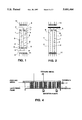
- FIGS. 1 and 2 there are shown cross-sections of a filter according to the invention.
- FIG. 3 there is shown a split open view of the plates in the filter in FIG. 1 and 2.
- FIG. 4 there is shown how the filter according to the invention may be used in the plant when the fluid is cooled prior to or during the filtration.
- FIG. 5 the arrangement of a number of filter sections are shown in a pasteurization plant.
- FIGS. 1 and 2 there are shown membrane plates 1 and impervious plates 2.
- FIG. 1 which is a cross-section of the filter along the line II--II in FIG. 3, there are shown the inlet openings 3 in the lower, front parts of both the plates 1,2 (as seen in FIG. 3). These inlet openings form the channel for unfiltered fluid. At the upper, front part of the plates there are outlet openings 4 forming the channel for permeate.
- FIG. 2 which is a cross-section of the filter along the line II--II in FIG. 3 there are shown the outlet openings 5 in the upper, rear part in the plates as seen in FIG. 3.
- the membrane plates are provided with a membrane 6 with the desired pore size.
- the retentate passages are sealed against the channels for permeate (formed by the openings 4) by packings 7.
- the permeate passages 8 are connected to the channels for permeate (formed by the openings 4) but sealed against the channel for unfiltered fluid by packings 9 and sealed against the channels for retentate by packings 10.
- the impervious plates are provided with a corrugation pattern (not shown in the drawing) facing the retentate passage.
- the unfiltered fluid enters the filter through the openings 3 and is divided into a number of parallel flows directed into the retentate passages 6. During the flow a part of the fluid passes the membrane in the membrane plates and enters the membrane passages 8. This flow, which has passed the membrane, leaves the membrane passages through the openings 5 forming the channel for permeate. The rest of the fluid leaves the retentate passages through the openings 5 forming the channel for retentate.
- a restriction (not shown in the drawing). With the aid of this restriction the permeate flow out from the filter may be throttled in a desired degree. Due to the restriction the permeate passages are kept filled with fluid the pressure of which may be controlled. The counterpressure over the membrane may then be kept at a desired degree.
- FIG. 3 The plates forming a filter according to the invention is shown in FIG. 3. From this drawing it may also be seen that the end plates in a separate filter section must be designed with a different number of openings than the plates within the filter section.
- FIG. 4 there is shown how a filter according to the invention may form part of a plant where the unfiltered fluid is cooled (see "cooling media") prior to the filtration and also during the same.
- the pressure of the fluid may also be increased during the passage through the filter, by using one or more conventional booster pumps, for example, a positive displacement pump or a centrifugal pump, if needed or desired.
- FIG. 5 there is shown how a number of filter sections may be included in a plant where the permeate also is pasteurized (see “steam” and “heating section") while the retentate is removed after the filtering.
- FIG. 5 also shows a "cooling media” and a “cooling section” in this embodiment.
Landscapes
- Chemical & Material Sciences (AREA)
- Chemical Kinetics & Catalysis (AREA)
- Separation Using Semi-Permeable Membranes (AREA)
- Filtration Of Liquid (AREA)
- Electrical Discharge Machining, Electrochemical Machining, And Combined Machining (AREA)
- Water Treatment By Sorption (AREA)
- Glass Compositions (AREA)
Abstract
Description
Claims (13)
Applications Claiming Priority (3)
| Application Number | Priority Date | Filing Date | Title |
|---|---|---|---|
| SE9302454A SE503277C2 (en) | 1993-07-20 | 1993-07-20 | Filters intended for cross-flow filtration |
| SE9302454 | 1993-07-20 | ||
| PCT/SE1994/000675 WO1995003109A1 (en) | 1993-07-20 | 1994-07-08 | Filter intended for cross-flow filtration |
Publications (1)
| Publication Number | Publication Date |
|---|---|
| US5681464A true US5681464A (en) | 1997-10-28 |
Family
ID=20390642
Family Applications (1)
| Application Number | Title | Priority Date | Filing Date |
|---|---|---|---|
| US08/582,988 Expired - Fee Related US5681464A (en) | 1993-07-20 | 1994-07-08 | Filter for cross-flow filtration |
Country Status (10)
| Country | Link |
|---|---|
| US (1) | US5681464A (en) |
| EP (1) | EP0710144B1 (en) |
| JP (1) | JPH09500577A (en) |
| AT (1) | ATE165746T1 (en) |
| CA (1) | CA2167278A1 (en) |
| DE (1) | DE69410094T2 (en) |
| DK (1) | DK0710144T3 (en) |
| ES (1) | ES2116604T3 (en) |
| SE (1) | SE503277C2 (en) |
| WO (1) | WO1995003109A1 (en) |
Cited By (30)
| Publication number | Priority date | Publication date | Assignee | Title |
|---|---|---|---|---|
| US20040020866A1 (en) * | 2002-07-22 | 2004-02-05 | Xerox Corporation | Liquid dispersion filtration and delivery apparatus and method |
| US20040173531A1 (en) * | 2002-07-22 | 2004-09-09 | Hammond John M. | Fluid separation and delivery apparatus and method |
| US20050233199A1 (en) * | 2004-04-05 | 2005-10-20 | Xingwu Wang | Hydrogen storage apparatus comprised of halloysite |
| US20050279695A1 (en) * | 2004-06-17 | 2005-12-22 | Millipore Corporation | Disposable integral filter unit |
| US20050279694A1 (en) * | 2004-06-17 | 2005-12-22 | Gregory Straeffer | Disposable integral filter unit |
| US20060076354A1 (en) * | 2004-10-07 | 2006-04-13 | Lanzafame John F | Hydrogen storage apparatus |
| US20060166810A1 (en) * | 2005-01-25 | 2006-07-27 | Gunderman Robert D | Ultracapacitors comprised of mineral microtubules |
| US20060163160A1 (en) * | 2005-01-25 | 2006-07-27 | Weiner Michael L | Halloysite microtubule processes, structures, and compositions |
| US20070235889A1 (en) * | 1997-11-14 | 2007-10-11 | Skyepharma, Inc. | Production of multivesicular liposomes |
| US20070289917A1 (en) * | 2006-06-15 | 2007-12-20 | Mylin John M | Separation system and method of operating |
| US7316780B1 (en) | 1999-01-29 | 2008-01-08 | Pall Corporation | Range separation devices and processes |
| US20080017564A1 (en) * | 2004-03-03 | 2008-01-24 | Hammond John M | Magnetic particle filtration apparatus |
| US20080041795A1 (en) * | 2005-02-24 | 2008-02-21 | Mann & Hummel Gmbh | Filter Unit, Filter Device and Filtration Process for Fluids |
| US20080164195A1 (en) * | 2004-03-19 | 2008-07-10 | Millipore Corporation | Prefilter system for biological systems |
| US20090255877A1 (en) * | 2008-04-11 | 2009-10-15 | Pall Corporation | Fluid treatment arrangements and methods |
| US20100018924A1 (en) * | 2008-07-28 | 2010-01-28 | Pall Corporation | Fluid treatment arrangements and methods |
| US20100059443A1 (en) * | 2008-09-02 | 2010-03-11 | Natrix Separations Inc. | Chromatography Membranes, Devices Containing Them, and Methods of Use Thereof |
| US20110117626A1 (en) * | 2009-11-13 | 2011-05-19 | Komkova Elena N | Hydrophobic Interaction Chromatography Membranes, and Methods of Use Thereof |
| US20110220573A1 (en) * | 2010-03-10 | 2011-09-15 | M-I L.L.C. | System and method for separating solids from fluids |
| WO2012158896A2 (en) | 2011-05-17 | 2012-11-22 | Natrix Separations Inc. | Layered tubular membranes for chromatography, and methods of use thereof |
| WO2014092727A1 (en) | 2012-12-14 | 2014-06-19 | General Electric Company | Flat reverse osmosis module and system |
| WO2014092725A1 (en) | 2012-12-14 | 2014-06-19 | General Electric Company | Membrane stack filtration module |
| WO2014207016A1 (en) * | 2013-06-25 | 2014-12-31 | Tetra Laval Holdings & Finance S.A. | Membrane filtration device having a hygienic suspension arrangement |
| US10005037B2 (en) | 2013-06-25 | 2018-06-26 | Tetra Laval Holdings & Finance S.A. | Memrane filtration device having an improved design |
| US10029213B2 (en) | 2010-03-10 | 2018-07-24 | M-I L.L.C. | System and method for separating solids from fluids |
| US10533796B2 (en) * | 2017-03-09 | 2020-01-14 | Larry Baxter | Method for thickening a cryogenic slurry using a cross-flow filter |
| WO2021099522A1 (en) | 2019-11-21 | 2021-05-27 | Merck Millipore Ltd. | Methods for coupling a ligand to a composite material |
| US11033495B1 (en) | 2021-01-22 | 2021-06-15 | Pacira Pharmaceuticals, Inc. | Manufacturing of bupivacaine multivesicular liposomes |
| US11278494B1 (en) | 2021-01-22 | 2022-03-22 | Pacira Pharmaceuticals, Inc. | Manufacturing of bupivacaine multivesicular liposomes |
| US11357727B1 (en) | 2021-01-22 | 2022-06-14 | Pacira Pharmaceuticals, Inc. | Manufacturing of bupivacaine multivesicular liposomes |
Families Citing this family (1)
| Publication number | Priority date | Publication date | Assignee | Title |
|---|---|---|---|---|
| AU1852700A (en) * | 1999-12-21 | 2001-07-03 | Kt Industries Inc. | Folded fluid absorbing strip |
Citations (10)
| Publication number | Priority date | Publication date | Assignee | Title |
|---|---|---|---|---|
| US2712386A (en) * | 1951-04-03 | 1955-07-05 | Standard Oil Co | Method and apparatus for separating materials by continuous liquid thermal diffusion |
| US3340186A (en) * | 1964-05-14 | 1967-09-05 | Research Corp | Recovery of demineralized water from saline waters |
| US4726900A (en) * | 1986-07-29 | 1988-02-23 | Vacco Industries | Stacked sheet filter element |
| US4797211A (en) * | 1985-12-24 | 1989-01-10 | Kernforschungszentrum Karlsruhe Gmbh | Cross flow microfilter |
| US5085772A (en) * | 1989-09-15 | 1992-02-04 | Eskofot A/S | Filter for filtration of fluids |
| WO1992003216A1 (en) * | 1990-08-15 | 1992-03-05 | Asea Brown Boveri Ab | Device for membrane separation |
| US5100544A (en) * | 1988-09-30 | 1992-03-31 | Daikin Industries, Ltd. | Liquid separating apparatus |
| US5104532A (en) * | 1989-09-15 | 1992-04-14 | Exxon Research And Engineering Company | Flat stack permeator |
| WO1992006774A1 (en) * | 1989-03-21 | 1992-04-30 | Goldsmith Susan H | Membrane-type filter and process of making |
| US5429742A (en) * | 1991-03-27 | 1995-07-04 | Pall Corporation | Plastic frame filter unit for a stack assembly |
-
1993
- 1993-07-20 SE SE9302454A patent/SE503277C2/en not_active IP Right Cessation
-
1994
- 1994-07-08 JP JP7505088A patent/JPH09500577A/en active Pending
- 1994-07-08 WO PCT/SE1994/000675 patent/WO1995003109A1/en active IP Right Grant
- 1994-07-08 CA CA002167278A patent/CA2167278A1/en not_active Abandoned
- 1994-07-08 ES ES94923121T patent/ES2116604T3/en not_active Expired - Lifetime
- 1994-07-08 US US08/582,988 patent/US5681464A/en not_active Expired - Fee Related
- 1994-07-08 DE DE69410094T patent/DE69410094T2/en not_active Expired - Fee Related
- 1994-07-08 DK DK94923121.1T patent/DK0710144T3/en active
- 1994-07-08 AT AT94923121T patent/ATE165746T1/en not_active IP Right Cessation
- 1994-07-08 EP EP94923121A patent/EP0710144B1/en not_active Expired - Lifetime
Patent Citations (10)
| Publication number | Priority date | Publication date | Assignee | Title |
|---|---|---|---|---|
| US2712386A (en) * | 1951-04-03 | 1955-07-05 | Standard Oil Co | Method and apparatus for separating materials by continuous liquid thermal diffusion |
| US3340186A (en) * | 1964-05-14 | 1967-09-05 | Research Corp | Recovery of demineralized water from saline waters |
| US4797211A (en) * | 1985-12-24 | 1989-01-10 | Kernforschungszentrum Karlsruhe Gmbh | Cross flow microfilter |
| US4726900A (en) * | 1986-07-29 | 1988-02-23 | Vacco Industries | Stacked sheet filter element |
| US5100544A (en) * | 1988-09-30 | 1992-03-31 | Daikin Industries, Ltd. | Liquid separating apparatus |
| WO1992006774A1 (en) * | 1989-03-21 | 1992-04-30 | Goldsmith Susan H | Membrane-type filter and process of making |
| US5085772A (en) * | 1989-09-15 | 1992-02-04 | Eskofot A/S | Filter for filtration of fluids |
| US5104532A (en) * | 1989-09-15 | 1992-04-14 | Exxon Research And Engineering Company | Flat stack permeator |
| WO1992003216A1 (en) * | 1990-08-15 | 1992-03-05 | Asea Brown Boveri Ab | Device for membrane separation |
| US5429742A (en) * | 1991-03-27 | 1995-07-04 | Pall Corporation | Plastic frame filter unit for a stack assembly |
Cited By (62)
| Publication number | Priority date | Publication date | Assignee | Title |
|---|---|---|---|---|
| US20070235889A1 (en) * | 1997-11-14 | 2007-10-11 | Skyepharma, Inc. | Production of multivesicular liposomes |
| US20140004173A1 (en) * | 1997-11-14 | 2014-01-02 | Pacira Pharmaceuticals, Inc. | Production of multivesicular liposomes |
| US9585838B2 (en) * | 1997-11-14 | 2017-03-07 | Pacira Pharmaceuticals, Inc. | Production of multivesicular liposomes |
| US7316780B1 (en) | 1999-01-29 | 2008-01-08 | Pall Corporation | Range separation devices and processes |
| US20040173531A1 (en) * | 2002-07-22 | 2004-09-09 | Hammond John M. | Fluid separation and delivery apparatus and method |
| US6852219B2 (en) | 2002-07-22 | 2005-02-08 | John M. Hammond | Fluid separation and delivery apparatus and method |
| US20040020866A1 (en) * | 2002-07-22 | 2004-02-05 | Xerox Corporation | Liquid dispersion filtration and delivery apparatus and method |
| US20080017564A1 (en) * | 2004-03-03 | 2008-01-24 | Hammond John M | Magnetic particle filtration apparatus |
| US7410574B2 (en) | 2004-03-03 | 2008-08-12 | Patent Innovations Llc | Magnetic particle filtration apparatus |
| US9072988B2 (en) | 2004-03-19 | 2015-07-07 | Emd Millipore Corporation | Prefilter system for biological systems |
| US20080164195A1 (en) * | 2004-03-19 | 2008-07-10 | Millipore Corporation | Prefilter system for biological systems |
| US20050233199A1 (en) * | 2004-04-05 | 2005-10-20 | Xingwu Wang | Hydrogen storage apparatus comprised of halloysite |
| US7425232B2 (en) | 2004-04-05 | 2008-09-16 | Naturalnano Research, Inc. | Hydrogen storage apparatus comprised of halloysite |
| US20050279694A1 (en) * | 2004-06-17 | 2005-12-22 | Gregory Straeffer | Disposable integral filter unit |
| US20050279695A1 (en) * | 2004-06-17 | 2005-12-22 | Millipore Corporation | Disposable integral filter unit |
| US20060076354A1 (en) * | 2004-10-07 | 2006-04-13 | Lanzafame John F | Hydrogen storage apparatus |
| US20060163160A1 (en) * | 2005-01-25 | 2006-07-27 | Weiner Michael L | Halloysite microtubule processes, structures, and compositions |
| US7400490B2 (en) | 2005-01-25 | 2008-07-15 | Naturalnano Research, Inc. | Ultracapacitors comprised of mineral microtubules |
| US7679883B2 (en) | 2005-01-25 | 2010-03-16 | Naturalnano Research, Inc. | Ultracapacitors comprised of mineral microtubules |
| US20100171081A1 (en) * | 2005-01-25 | 2010-07-08 | Naturalnano Research, Inc. | Ultracapacitors comprised of mineral microtubules |
| US20060166810A1 (en) * | 2005-01-25 | 2006-07-27 | Gunderman Robert D | Ultracapacitors comprised of mineral microtubules |
| US7641804B2 (en) * | 2005-02-24 | 2010-01-05 | Mann + Hummel Gmbh | Filter unit, filter device and filtration process for fluids |
| US20080041795A1 (en) * | 2005-02-24 | 2008-02-21 | Mann & Hummel Gmbh | Filter Unit, Filter Device and Filtration Process for Fluids |
| US20070289917A1 (en) * | 2006-06-15 | 2007-12-20 | Mylin John M | Separation system and method of operating |
| US20090255877A1 (en) * | 2008-04-11 | 2009-10-15 | Pall Corporation | Fluid treatment arrangements and methods |
| US8043512B2 (en) | 2008-04-11 | 2011-10-25 | Pall Corporation | Fluid treatment arrangements and methods |
| US8048315B2 (en) | 2008-07-28 | 2011-11-01 | Pall Corporation | Fluid treatment arrangements and methods |
| US20100018924A1 (en) * | 2008-07-28 | 2010-01-28 | Pall Corporation | Fluid treatment arrangements and methods |
| US20100059443A1 (en) * | 2008-09-02 | 2010-03-11 | Natrix Separations Inc. | Chromatography Membranes, Devices Containing Them, and Methods of Use Thereof |
| US11884701B2 (en) | 2008-09-02 | 2024-01-30 | Merck Millipore Ltd. | Chromatography membranes, devices containing them, and methods of use thereof |
| US10981949B2 (en) | 2008-09-02 | 2021-04-20 | Merck Millipore Ltd. | Chromatography membranes, devices containing them, and methods of use thereof |
| EP2334413A4 (en) * | 2008-09-02 | 2013-09-18 | Natrix Separations Inc | Chromatography membranes, devices containing them, and methods of use thereof |
| EP2334413A2 (en) * | 2008-09-02 | 2011-06-22 | Natrix Separations Inc. | Chromatography membranes, devices containing them, and methods of use thereof |
| US10800808B2 (en) | 2008-09-02 | 2020-10-13 | Merck Millipore Ltd. | Chromatography membranes, devices containing them, and methods of use thereof |
| US20110117626A1 (en) * | 2009-11-13 | 2011-05-19 | Komkova Elena N | Hydrophobic Interaction Chromatography Membranes, and Methods of Use Thereof |
| WO2011112772A3 (en) * | 2010-03-10 | 2011-11-24 | M-I L.L.C. | System and method for separating solids from fluids |
| US8877064B2 (en) | 2010-03-10 | 2014-11-04 | M-I L.L.C. | System and method for separating solids from fluids |
| US20110220573A1 (en) * | 2010-03-10 | 2011-09-15 | M-I L.L.C. | System and method for separating solids from fluids |
| US10029213B2 (en) | 2010-03-10 | 2018-07-24 | M-I L.L.C. | System and method for separating solids from fluids |
| US10195567B2 (en) | 2011-05-17 | 2019-02-05 | Natrix Separations Inc. | Layered tubular membranes for chromatography, and methods of use thereof |
| WO2012158896A2 (en) | 2011-05-17 | 2012-11-22 | Natrix Separations Inc. | Layered tubular membranes for chromatography, and methods of use thereof |
| US10874990B2 (en) | 2011-05-17 | 2020-12-29 | Merck Millipore Ltd. | Layered tubular membranes for chromatography, and methods of use thereof |
| US9873088B2 (en) | 2011-05-17 | 2018-01-23 | Natrix Separations Inc. | Layered tubular membranes for chromatography, and methods of use thereof |
| WO2014092727A1 (en) | 2012-12-14 | 2014-06-19 | General Electric Company | Flat reverse osmosis module and system |
| WO2014092725A1 (en) | 2012-12-14 | 2014-06-19 | General Electric Company | Membrane stack filtration module |
| US10005037B2 (en) | 2013-06-25 | 2018-06-26 | Tetra Laval Holdings & Finance S.A. | Memrane filtration device having an improved design |
| US9776138B2 (en) | 2013-06-25 | 2017-10-03 | Tetra Laval Holdings & Finance S.A. | Membrane filtration device having a hygienic suspension arrangement |
| WO2014207016A1 (en) * | 2013-06-25 | 2014-12-31 | Tetra Laval Holdings & Finance S.A. | Membrane filtration device having a hygienic suspension arrangement |
| US10533796B2 (en) * | 2017-03-09 | 2020-01-14 | Larry Baxter | Method for thickening a cryogenic slurry using a cross-flow filter |
| WO2021099522A1 (en) | 2019-11-21 | 2021-05-27 | Merck Millipore Ltd. | Methods for coupling a ligand to a composite material |
| US11179336B1 (en) | 2021-01-22 | 2021-11-23 | Pacira Pharmaceuticals, Inc. | Manufacturing of bupivacaine multivesicular liposomes |
| US11185506B1 (en) | 2021-01-22 | 2021-11-30 | Pacira Pharmaceuticals, Inc. | Manufacturing of bupivacaine multivesicular liposomes |
| US11278494B1 (en) | 2021-01-22 | 2022-03-22 | Pacira Pharmaceuticals, Inc. | Manufacturing of bupivacaine multivesicular liposomes |
| US11304904B1 (en) | 2021-01-22 | 2022-04-19 | Pacira Pharmaceuticals, Inc. | Manufacturing of bupivacaine multivesicular liposomes |
| US11311486B1 (en) | 2021-01-22 | 2022-04-26 | Pacira Pharmaceuticals, Inc. | Manufacturing of bupivacaine multivesicular liposomes |
| US11357727B1 (en) | 2021-01-22 | 2022-06-14 | Pacira Pharmaceuticals, Inc. | Manufacturing of bupivacaine multivesicular liposomes |
| US11426348B2 (en) | 2021-01-22 | 2022-08-30 | Pacira Pharmaceuticals, Inc. | Compositions of bupivacaine multivesicular liposomes |
| US11452691B1 (en) | 2021-01-22 | 2022-09-27 | Pacira Pharmaceuticals, Inc. | Compositions of bupivacaine multivesicular liposomes |
| US11819575B2 (en) | 2021-01-22 | 2023-11-21 | Pacira Pharmaceuticals, Inc. | Manufacturing of bupivacaine multivesicular liposomes |
| US11819574B2 (en) | 2021-01-22 | 2023-11-21 | Pacira Pharmaceuticals, Inc. | Manufacturing of bupivacaine multivesicular liposomes |
| US11033495B1 (en) | 2021-01-22 | 2021-06-15 | Pacira Pharmaceuticals, Inc. | Manufacturing of bupivacaine multivesicular liposomes |
| US11925706B2 (en) | 2021-01-22 | 2024-03-12 | Pacira Pharmaceuticals, Inc. | Manufacturing of bupivacaine multivesicular liposomes |
Also Published As
| Publication number | Publication date |
|---|---|
| CA2167278A1 (en) | 1995-02-02 |
| WO1995003109A1 (en) | 1995-02-02 |
| DK0710144T3 (en) | 1998-06-02 |
| EP0710144A1 (en) | 1996-05-08 |
| ES2116604T3 (en) | 1998-07-16 |
| DE69410094T2 (en) | 1998-09-03 |
| SE9302454L (en) | 1995-01-21 |
| SE503277C2 (en) | 1996-05-13 |
| DE69410094D1 (en) | 1998-06-10 |
| SE9302454D0 (en) | 1993-07-20 |
| JPH09500577A (en) | 1997-01-21 |
| ATE165746T1 (en) | 1998-05-15 |
| EP0710144B1 (en) | 1998-05-06 |
Similar Documents
| Publication | Publication Date | Title |
|---|---|---|
| US5681464A (en) | Filter for cross-flow filtration | |
| JP3466878B2 (en) | Disposable membrane module with small dead volume | |
| US4906362A (en) | Arrangement in membrane filter | |
| US5906739A (en) | Membrane filtration assembly | |
| US7691266B2 (en) | Separation devices and processes | |
| EP1499425B1 (en) | Anti-telescoping device for spiral wound membrane modules and method of use | |
| US6368505B1 (en) | Cross-flow filter cartridge | |
| US20050126980A1 (en) | Cross-flow filtration unit | |
| US4801381A (en) | Ultrafiltration apparatus | |
| US11654397B2 (en) | Filter cassette article, and filter comprising same | |
| JPH03135405A (en) | Filtering device for fluid operatable on crossflow principle | |
| US10576425B2 (en) | Unhoused filtration device and methods of use | |
| CA1204674A (en) | Apparatus for separating liquid feed mixtures into two fractions by means of semipermeable membranes | |
| EP1148929B1 (en) | Cross-flow separation devices and processes |
Legal Events
| Date | Code | Title | Description |
|---|---|---|---|
| AS | Assignment |
Owner name: ALFA LAVAL BREWERY SYSTEMS AB, SWEDEN Free format text: ASSIGNMENT OF ASSIGNORS INTEREST;ASSIGNOR:LARSSON, EBBE;REEL/FRAME:007994/0412 Effective date: 19960322 |
|
| FEPP | Fee payment procedure |
Free format text: PAYOR NUMBER ASSIGNED (ORIGINAL EVENT CODE: ASPN); ENTITY STATUS OF PATENT OWNER: LARGE ENTITY |
|
| AS | Assignment |
Owner name: ALFA LAVAL AB, SWEDEN Free format text: ASSIGNMENT OF ASSIGNORS INTEREST;ASSIGNOR:ALFA LAVAL BREWERY SYSTEMS AB;REEL/FRAME:010263/0621 Effective date: 19990915 |
|
| REMI | Maintenance fee reminder mailed | ||
| LAPS | Lapse for failure to pay maintenance fees | ||
| STCH | Information on status: patent discontinuation |
Free format text: PATENT EXPIRED DUE TO NONPAYMENT OF MAINTENANCE FEES UNDER 37 CFR 1.362 |
|
| FP | Lapsed due to failure to pay maintenance fee |
Effective date: 20011028 |