US5663733A - Digital bandwidth compression for optimum tracking in satellite positioning system receiver - Google Patents
Digital bandwidth compression for optimum tracking in satellite positioning system receiver Download PDFInfo
- Publication number
- US5663733A US5663733A US08/520,332 US52033295A US5663733A US 5663733 A US5663733 A US 5663733A US 52033295 A US52033295 A US 52033295A US 5663733 A US5663733 A US 5663733A
- Authority
- US
- United States
- Prior art keywords
- code
- signal
- carrier
- multiplier
- nco
- Prior art date
- Legal status (The legal status is an assumption and is not a legal conclusion. Google has not performed a legal analysis and makes no representation as to the accuracy of the status listed.)
- Expired - Fee Related
Links
Images


Classifications
-
- G—PHYSICS
- G01—MEASURING; TESTING
- G01S—RADIO DIRECTION-FINDING; RADIO NAVIGATION; DETERMINING DISTANCE OR VELOCITY BY USE OF RADIO WAVES; LOCATING OR PRESENCE-DETECTING BY USE OF THE REFLECTION OR RERADIATION OF RADIO WAVES; ANALOGOUS ARRANGEMENTS USING OTHER WAVES
- G01S19/00—Satellite radio beacon positioning systems; Determining position, velocity or attitude using signals transmitted by such systems
- G01S19/01—Satellite radio beacon positioning systems transmitting time-stamped messages, e.g. GPS [Global Positioning System], GLONASS [Global Orbiting Navigation Satellite System] or GALILEO
- G01S19/13—Receivers
- G01S19/32—Multimode operation in a single same satellite system, e.g. GPS L1/L2
-
- G—PHYSICS
- G01—MEASURING; TESTING
- G01S—RADIO DIRECTION-FINDING; RADIO NAVIGATION; DETERMINING DISTANCE OR VELOCITY BY USE OF RADIO WAVES; LOCATING OR PRESENCE-DETECTING BY USE OF THE REFLECTION OR RERADIATION OF RADIO WAVES; ANALOGOUS ARRANGEMENTS USING OTHER WAVES
- G01S19/00—Satellite radio beacon positioning systems; Determining position, velocity or attitude using signals transmitted by such systems
- G01S19/01—Satellite radio beacon positioning systems transmitting time-stamped messages, e.g. GPS [Global Positioning System], GLONASS [Global Orbiting Navigation Satellite System] or GALILEO
- G01S19/13—Receivers
- G01S19/21—Interference related issues ; Issues related to cross-correlation, spoofing or other methods of denial of service
- G01S19/215—Interference related issues ; Issues related to cross-correlation, spoofing or other methods of denial of service issues related to spoofing
-
- G—PHYSICS
- G01—MEASURING; TESTING
- G01S—RADIO DIRECTION-FINDING; RADIO NAVIGATION; DETERMINING DISTANCE OR VELOCITY BY USE OF RADIO WAVES; LOCATING OR PRESENCE-DETECTING BY USE OF THE REFLECTION OR RERADIATION OF RADIO WAVES; ANALOGOUS ARRANGEMENTS USING OTHER WAVES
- G01S19/00—Satellite radio beacon positioning systems; Determining position, velocity or attitude using signals transmitted by such systems
- G01S19/01—Satellite radio beacon positioning systems transmitting time-stamped messages, e.g. GPS [Global Positioning System], GLONASS [Global Orbiting Navigation Satellite System] or GALILEO
- G01S19/13—Receivers
- G01S19/24—Acquisition or tracking or demodulation of signals transmitted by the system
- G01S19/29—Acquisition or tracking or demodulation of signals transmitted by the system carrier including Doppler, related
-
- G—PHYSICS
- G01—MEASURING; TESTING
- G01S—RADIO DIRECTION-FINDING; RADIO NAVIGATION; DETERMINING DISTANCE OR VELOCITY BY USE OF RADIO WAVES; LOCATING OR PRESENCE-DETECTING BY USE OF THE REFLECTION OR RERADIATION OF RADIO WAVES; ANALOGOUS ARRANGEMENTS USING OTHER WAVES
- G01S19/00—Satellite radio beacon positioning systems; Determining position, velocity or attitude using signals transmitted by such systems
- G01S19/01—Satellite radio beacon positioning systems transmitting time-stamped messages, e.g. GPS [Global Positioning System], GLONASS [Global Orbiting Navigation Satellite System] or GALILEO
- G01S19/13—Receivers
- G01S19/24—Acquisition or tracking or demodulation of signals transmitted by the system
- G01S19/30—Acquisition or tracking or demodulation of signals transmitted by the system code related
-
- G—PHYSICS
- G01—MEASURING; TESTING
- G01S—RADIO DIRECTION-FINDING; RADIO NAVIGATION; DETERMINING DISTANCE OR VELOCITY BY USE OF RADIO WAVES; LOCATING OR PRESENCE-DETECTING BY USE OF THE REFLECTION OR RERADIATION OF RADIO WAVES; ANALOGOUS ARRANGEMENTS USING OTHER WAVES
- G01S19/00—Satellite radio beacon positioning systems; Determining position, velocity or attitude using signals transmitted by such systems
- G01S19/01—Satellite radio beacon positioning systems transmitting time-stamped messages, e.g. GPS [Global Positioning System], GLONASS [Global Orbiting Navigation Satellite System] or GALILEO
- G01S19/13—Receivers
- G01S19/35—Constructional details or hardware or software details of the signal processing chain
- G01S19/37—Hardware or software details of the signal processing chain
Definitions
- the invention relates to a satellite positioning system (SPS) receiver capable of receiving satellite signals which have been modulated with an unknown security code.
- SPS includes different satellite systems. One of those systems is a global positioning system (GPS).
- GPS global positioning system
- the GPS is a system of satellite signal transmitters, with receivers located on the Earth's surface or adjacent to the Earth's surface, that transmits information from which an observer's present location and/or the time of observation can be determined.
- GLONASS Global Orbiting Navigational System
- the GPS is part of a satellite-based navigation system developed by the United States Defense Department under its NAVSTAR satellite program.
- a fully operational GPS includes up to 24 Earth orbiting satellites approximately uniformly dispersed around six circular orbits with four satellites each, the orbits being inclined at an angle of 55° relative to the equator and being separated from each other by multiples of 60° longitude.
- the orbits have radii of 26,560 kilometers and are approximately circular.
- the orbits are non-geosynchronous, with 0.5 sidereal day (11.967 hours) orbital time intervals, so that the satellites move with time relative to the Earth below.
- GPS satellites will be visible from most points on the Earth's surface, and visual access to four or more such satellites can be used to determine an observer's position anywhere on the Earth's surface, 24 hours per day.
- Each satellite carries a cesium or rubidium atomic clock to provide timing information for the signals transmitted by the satellites. Internal clock correction is provided for each satellite clock.
- the L1 signal from each satellite is binary phase shift key (BPSK) modulated by two pseudo-random noise (PRN) codes in phase quadrature, designated as the C/A-code and P-code.
- PRN pseudo-random noise
- the L2 signal from each satellite is BPSK modulated by only the P-code. The nature of these PRN codes is described below.
- phase delay associated with a given carrier signal can also be determined.
- the phase delay which is proportional to the time difference of arrival of the modulated signals is measured in real time by cross correlating two coherently modulated signals transmitted at different frequencies L1 and L2 from the spacecraft to the receiver using a cross correlator.
- a variable delay is adjusted relative to a fixed delay in the respective channels L1 and L2 to produce a maximum at the cross correlator output. The difference in delay required to produce this maximum is a measure of the columnar electron content of the ionosphere.
- PRN codes allows use of a plurality of GPS satellite signals for determining an observer's position and for providing the navigation information.
- a signal transmitted by a particular GPS satellite is selected by generating and matching, or correlating, the PRN code for that particular satellite.
- Some of the PRN codes are known and are generated or stored in GPS satellite signal receivers carried by ground observers. Some of the PRN codes are unknown.
- the C/A-code for any GPS satellite has a length of 1023 chips or time increments before this code repeats.
- the full P-code has a length of 259 days, with each satellite transmitting a unique portion of the full P-code.
- the portion of P-code used for a given GPS satellite has a length of precisely one week (7.000 days) before this code portion repeats.
- Accepted methods for generating the C/A-code and P-code are set forth in the document GPS Interface Control Document ICD-GPS-200, published by Rockwell International Corporation, Satellite Systems Division, Revision B-PR, 3 Jul. 1991, which is incorporated by reference herein.
- the GPS satellite bit stream includes navigational information on the ephemeris of the transmitting GPS satellite (which includes complete information about the transmitting satellite within the next several hours of transmission) and an almanac for all GPS satellites (which includes less detailed information about all other satellites).
- the satellite information transmitted by the transmitting GPS has the parameters providing corrections for ionospheric signal propagation delays suitable for single frequency receivers and for an offset time between satellite clock time and true GPS time.
- the navigational information is transmitted at a rate of 50 Baud.
- GLONASS Global Orbiting Navigation Satellite System
- GLONASS Global Orbiting Navigation Satellite System
- GLONASS also uses 24 satellites, distributed approximately uniformly in three orbital planes of eight satellites each. Each orbital plane has a nominal inclination of 64.8° relative to the equator, and the three orbital planes are separated from each other by multiples of 120° longitude.
- the GLONASS circular orbits have smaller radii, about 25,510 kilometers, and a satellite period of revolution of 8/17 of a sidereal day (11.26 hours).
- a GLONASS satellite and a GPS satellite will thus complete 17 and 16 revolutions, respectively, around the Earth every 8 days.
- the L2 code is presently modulated only by the P-code.
- the GLONASS satellites transmit navigational data at a rate of 50 Baud for C/A code and 100 Baud for P code. Because the channel frequencies are distinguishable from each other, the P-code is the same, and the C/A-code is the same, for each satellite.
- the methods for receiving and analyzing the GLONASS signals are similar to the methods used for the GPS signals.
- Reference to a Satellite Positioning System or SPS herein refers to a Global Positioning System, to a Global Orbiting Navigation System, and to any other compatible satellite-based system that provides information by which an observer's position and the time of observation can be determined, all of which meet the requirements of the present invention.
- a Satellite Positioning System such as the Global Positioning System (GPS) or the Global Orbiting Navigation Satellite System (GLONASS) uses transmission of coded radio signals, with the structure described above, from a plurality of Earth-orbiting satellites.
- An SPS antenna receives SPS signals from a plurality (preferably four or more) of SPS satellites and passes these signals to an SPS signal receiver/processor, which (1) identifies the SPS satellite source for each SPS signal, (2) determines the time at which each identified SPS signal arrives at the antenna, and (3) determines the present location of the SPS satellites.
- the range (Ri) between the location of the i-th SPS satellite and the SPS receiver is equal to the speed of light c times ( ⁇ ti), wherein ( ⁇ ti) is the time difference between the SPS receiver's clock and the time indicated by the satellite when it transmitted the relevant phase.
- ⁇ ti is the time difference between the SPS receiver's clock and the time indicated by the satellite when it transmitted the relevant phase.
- the SPS receiver has an inexpensive quartz clock which is not synchronized with respect to the much more stable and precise atomic clocks carried on board the satellites. Consequently, the SPS receiver actually estimates not the true range Ri to the satellite but only the pseudo-range (ri) to each SPS satellite.
- the SPS receiver After the SPS receiver determines the coordinates of the i-th SPS satellite by picking up transmitted ephemeris constants, the SPS receiver can obtain the solution of the set of the four equations for its unknown coordinates (x0, y0, z0) and for unknown time bias error (cb). The SPS receiver can also obtain its heading and speed. (See The Navstar Global Positioning System, Tom Logsdon, Van Nostrand Reinhold, 1992, pp. 8-33, 44-75, 128-187.) The following discussion is focused on the GPS receiver, though the same approach can be used for any other SPS receiver.
- the C/A code modulated phase quadrature carrier component of the L1 signal is provided for commercial use. If the accuracy desired in the quantity being measured by the receiver is not great, it is sufficient to use only the L1 signal carrier. However, for applications where high resolution measurements or fast high integrity measurements are to be made, e.g. surveying and machine control, both the L1 carrier and the L2 carrier must also be used, which allows elimination of the unknown component of the time delay of the signals by the ionosphere.
- the satellites are provided with a secret Y-code, which replaces the known P-code when the "anti-spoofing" is ON.
- the Y-code is turned OFF, and the known P-code is used.
- the secret Y-code can be turned ON or OFF at will by the U.S. Government.
- the "anti-spoofing” allows the GPS system to be used for the military or other classified United States Government projects. It has been disclosed publicly that the secret Y-code is the modulo-two sum of the known P-code and the unknown W-code. Since the W-code is classified, the commercial GPS users employ different techniques to obtain the quasi-demodulation of the L2 signal.
- the GPS signals are intended to be recovered by correlating each incoming signal with a locally generated replica of the code: P-code or C/A code.
- the result of such correlation is that the carrier in the GPS signals is totally suppressed when the modulating signal is a pseudorange code sequence like the P-code or the C/A code.
- the received L2 signal contains no significant components at the L2 frequency.
- the P code is not encrypted, the L2 carrier is easily recovered by correlation of the received signal with the locally generated P code replica.
- the locally generated code is adjusted in timing to provide an optimum correlation with the incoming signal.
- the correlation output is then a single narrowband peak centered at the carrier frequency.
- the carrier recovered by correlation provides the best available signal-to-noise ratio (SNR).
- SNR signal-to-noise ratio
- the L2 carrier cannot be recovered by this correlation process when the P code is encrypted, L2 can still be recovered by squaring (multiplying the signal by itself) the incoming signal. This has an effect of removing all biphase modulation from the signal, and producing a single-frequency output signal at twice the frequency of the suppressed carrier.
- the L2 carrier can be obtained by squaring, regardless of whether or not the modulating P code is encrypted.
- the squaring the signal also squares the noise component of the signal.
- the resulting SNR is seriously degraded (by 30 dB or more) as compared with the ratio for the carrier recovered by correlation.
- squaring provides the half-wavelength carrier phase which is different from the L2 real wavelength carrier phase.
- U.S. Pat. No. 4,972,431 issued to Keegan discloses a different approach to the quasi-demodulation of the L2 signal.
- the incoming encrypted P-code GPS signal is not immediately squared. Instead, after mixing with a local oscillator signal to lower its frequency to an intermediate frequency, the encrypted P-code signal is correlated with a locally generated P-code signal. Since the locally generated P-code signal does not perfectly match the encrypted P-code sequence, the correlation does not produce a sharp peak in the frequency spectrum.
- the result of the correlation is filtered by a bandpass filter, and the reduced-bandwidth signal is squared.
- the squared signal is processed in a delay lock code loop to maximize the spectral peak.
- An error signal is generated and is fed back to control the generator of P code signal as to maximize the peak in the frequency spectrum of the output signal and to effectively lock onto the incoming L2 P code signal.
- the second harmonic of the suppressed carrier signal resulting from the squaring process is processed to provide L2 carrier phase measurements. Because the squaring step is performed over a narrower bandwidth than the original P-code, there is less degradation in the SNR of the received signal, as compared with squaring over the entire P-code bandwidth. The performance is more reliable under weak signal conditions because the cycle ambiguity of the carrier signal can be resolved more rapidly. The invention does not frustrate the intended purpose of P-code encryption.
- What is needed is a SPS receiver capable of achieving an optimally high L2 SNR on every satellite without requiring detailed knowledge of the secret W code structure. This can be done by observing the GPS satellites and discovering general W code structure information which is always present on every satellite observed and subsequently optimizing the SPS receiver design to these characteristics. This general structure being present on all satellites ensures that the SPS receiver design presented here will operate similarly and optimally for all satellites tracked.
- the present invention is unique because it allows the design of a high SNR SPS receiver capable of processing the satellite signals with an unknown W-code without making any assumptions about the W-code timing information.
- One aspect of the present invention is directed to a system for optimum correlation processing of L1 and L2 signals received from a SPS satellite by a SPS RECEIVER.
- the system comprises: (A) a RECEIVING MEANS for receiving a known C/A code modulated on L1 carrier frequency, for receiving an unknown Y code modulated on L1 carrier frequency signal, and for receiving an unknown Y code modulated on L2 carrier frequency signal from at least one satellite; wherein said received L1, and L2 signals contain propagation noise; and wherein said Y code comprises a known P code and an unknown W code; and (B) at least one DIGITAL CHANNEL PROCESSING MEANS for: (1) locally generating replica of the C/A code modulated on the L1 carrier frequency signal; (2) locally generating replica of the P code modulated on L1 carrier frequency signal, wherein the locally generated replica of L1 signal does not contain propagation noise; (3) locally generating replica of the P code modulated on L2 carrier frequency signal, wherein the locally generated replica of L2 signal does
- the L1 W code is not synchronized to the signal C/A EPOCH 1, and the L2 W code signal is not synchronized to the signal C/A EPOCH 2.
- the L1 W-code is synchronized and shifted in time in respect to the signal C/A code EPOCH 1, and the L2 W- code is synchronized and shifted in time in respect to the signal C/A code EPOCH 2.
- the RECEIVING MEANS further comprises a dual frequency patch ANTENNA for receiving the L1 and L2 satellite signals; a FILTER/LNA conductively connected to the ANTENNA for performing filtering and low noise amplification of the L1 and L2 signals, wherein the FILTER/LNA determines the signal/noise ratio (SNR) of the received signals L1 and L2; a DOWNCONVERTER conductively connected to the FILTER/LNA for mixing and converting the L1 and L2 signals; and an IF PROCESSOR conductively connected to the DOWNCONVERTER for transforming the converted L1 and L2 signals into digitally sampled quadrature versions of L1 and L2 signals (IL1, QL1, IL2, QL2).
- the system further comprises a MASTER OSCILLATOR and a FREQUENCY SYNTHESIZER for generating several timing signals.
- the FILTER/LNA further includes a POWER SPLITTER for power splitting a single L1/L2 signal received by the ANTENNA into two separate L1 and L2 signals; two separate BANDPASS FILTERs connected to the POWER SPLITTER for filtering the L1 and L2 signals independently; and a POWER COMBINER for power combining the L1 and L2 signals into one combined signal L1/L2 before feeding the combined L1/L2 signal into the LNA.
- the LNA outputs amplified and filtered combined L1/L2 signal.
- the FREQUENCY SYNTHESIZER further comprises a PHASE DETECTOR for comparing phases of two signals, wherein the first signal is an output signal from the MASTER OSCILLATOR, and wherein the second signal is generated by the FREQUENCY SYNTHESIZER, and wherein minimum voltage output signal from the PHASE DETECTOR represents the maximum phase alignment of the two signals.
- the FREQUENCY SYNTHESIZER further includes a LOOP FILTER for filtering out high frequency voltage noise, wherein an output LOOP FILTER voltage signal includes a low frequency voltage noise.
- a VOLTAGE CONTROLLED OSCILLATOR (VCO) is connected to the LOOP FILTER, wherein a voltage signal at the input of the VCO causes frequency change in the VCO output signal, and wherein the VCO nominal output signal is locked to the reference signal; and wherein the VCO nominal output signal is used as 1st local oscillator (LO1) signal.
- a first DIVIDER MEANS is connected to the VCO for dividing the VCO output signal to obtain the 2nd local oscillator (LO2) signal.
- a second DIVIDER connected to the first DIVIDER MEANS divides the 2nd LO2 signal to obtain the sampling clock (SCLK).
- SCLK sampling clock
- a third DIVIDER is connected to the second DIVIDER for dividing the 2nd LO2 signal and for obtaining the signal MSEC used for measurement of local reference time.
- the DIGITAL CHANNEL PROCESSING MEANS further comprises an L1 TRACKER for tracking L1 C/A code when encryption is ON and for tracking L1 P code when encryption is OFF; an L2 TRACKER connected to the L1 TRACKER for tracking an optimized enhanced cross-correlated W code when encryption is ON and for tracking L2 P code when encryption is OFF; and a MICROPROCESSOR SYSTEM connected to the L1 TRACKER and to the L2 TRACKER.
- the L1 TRACKER is fed by digitized inphase IL1 and quadrature QL1 of L1 signal outputted by the IF PROCESSOR.
- the L2 TRACKER is fed by digitized inphase I and quadrature Q components of L2 signal outputted by the IF PROCESSOR MEANS. Both the L1 TRACKER and the L2 TRACKER are synchronously clocked by SCLK signal and are synchronously referenced by MSEC signal to local reference time.
- the L2 TRACKER MEANS is fed from the L1 TRACKER MEANS by ⁇ W L1 signal.
- the L1 TRACKER for optimized enhanced cross correlation further comprises a CODE GENERATOR 1 for providing a locally generated replica of C/A code, and for providing a locally generated replica of P code; a MULTIPLEXER 1 for selecting a locally generated code C/A when Y code is ON and for selecting a locally generated P code when Y code is OFF, a carrier numerically controlled oscillator (CARRIER NCO MEANS 1); a CARRIER MIXER MEANS 1 for multiplying outputted by the IF PROCESSOR digitized inphase IL1 and Q L1 signals having carrier frequency with outputted by the CARRIER NCO 1 inphase and quadrature components of digital carrier; wherein the CARRIER MIXER MEANS 1 outputs inphase I and quadrature Q signals having zero carrier frequency.
- CARRIER NCO MEANS 1 carrier numerically controlled oscillator
- a CODE MIXER 1 is connected to the CARRIER MIXER 1 and to the MULTIPLEXER 1 for code correlating the CARRIER MIXER 1 output signals with the locally generated replica of C/A code or P-code.
- the L1 TRACKER's carrier tracking loop is closed via the CARRIER NCO 1 the input to the CODE MIXER 1 represents the satellite signal L1 C/A code, wherein the CODE MIXER 1 performs the code correlation at 3 time points (early, punctual and late) on the autocorrelation function graph creating an early, a punctual and a late sample of the autocorrelation function.
- the LI TRACKER further includes a block CORRELATORS 1 connected to the CODE MIXER 1 for integrating the early, punctual and late samples of the autocorrelation function over an integer multiple of EPOCH 1 signals; wherein the CORRELATORS 1 output signal is fed to the MICROPROCESSOR SYSTEM at a rate of L1 C/A code EPOCH 1, and wherein the MICROPROCESSOR uses the CORRELATORS 1 output signal to develop feedback signals for the L1 carrier tracking loop and for the L1 code tracking loop.
- a code numerically controlled oscillator (CODE NCO 1) connected to the CODE GENERATOR 1 provides a signal at the P-code rate for driving the CODE GENERATOR 1.
- the CODE NCO 1 also provides a mechanism for aligning the locally generated replica of C/A code or P-code with the incoming satellite C/A code or P-code.
- a CARRIER MIXER 1 generates in its Q channel an estimate of L1 Y code as an input to the CODE MIXER 2 when the L1 TRACKER is tracking L1 C/A code.
- a CODE GENERATOR 1 outputs a local replica of known L1 P code as an input to the CODE MIXER 2.
- the CODE MIXER 2 removes the known L1 P code from the estimate of L1 Y code and outputs an estimate of L1 W code.
- the estimate of L1 W code is accumulated by a DIGITAL SUMMER 1 over periods given by a W SYNC 1 signal outputted by the CODE GENERATOR 1.
- the DIGITAL SUMMER 1 outputs a ⁇ W L1 signal for further processing by the L2 TRACKER MEANS block, wherein the ⁇ W L1 signal represents a series of accumulated L1 W code at the rate of the W SYNC 1 signal.
- the W SYNC 1 signal represents a period of 22 L1 P(Y) code clocks, and the W SYNC 1 signal is synchronized with the L1 C/A code EPOCH 1 signal.
- the CODE GENERATOR 1 further comprises: (1) a first DIVIDING MEANS for dividing an input signal from the CODE NCO 1 to provide a C/A CODE GENERATOR clock signal; (2) a C/A CODE GENERATOR MEANS connected to the first DIVIDING MEANS for generating the C/A code signal and the EPOCH 1 signal under the CONTROL signal of the MICROPROCESSOR, wherein the C/A code signal is the locally generated C/A code, and wherein the EPOCH 1 signal is the repetition rate of the C/A code, and wherein the C/A CODE GENERATOR can be adjusted under CONTROL signal to generate a particular satellite's C/A code; (3) a P CODE GENERATOR connected to the CODE NCO 1, wherein the P CODE GENERATOR is clocked by the CODE NCO 1 signal under the CONTROL signal of the MICROPROCESSOR, and wherein the P CODE GENERATOR generates a P-code signal, and
- the DIVIDE BY N block comprises a DIVIDE BY 22 block
- the first DIVIDING MEANS comprises a DIVIDE BY 10 block
- the ⁇ delay is equal to zero.
- the DIGITAL SUMMER 1 further comprises a DIGITAL SUMMER ACCUMULATOR block accumulating the L1 W code over the period of W SYNC 1 signal and outputting an ⁇ W L1 signal equal to an ⁇ (L1W) code accumulation during said W SYNC 1 period.
- the L2 TRACKER MEANS further comprises a carrier numerically controlled oscillator (CARRIER NCO MEANS 2); a CARRIER MIXER MEANS 2 connected to the CARRIER NCO MEANS 2 for mixing outputted by the IF PROCESSOR MEANS digitized inphase I L2 and Q L2 signals having carrier frequency with outputted by the CARRIER NCO MEANS 2 inphase and quadrature components of digital carrier.
- the CARRIER MIXER 2 outputs inphase I L2 and quadrature Q L2 signals having zero carrier frequency.
- the I output of the CARRIER MIXER 2 represents an estimate of L2 Y code
- the Q output of the CARRIER MIXER 2 contains no signal power.
- a CODE NCO 2 is controlled by the L2 code tracking loop.
- a CODE GENERATOR 2 is connected to the CODE NCO 2, wherein the CODE NCO 2 drives the CODE GENERATOR 2 to produce a locally generated P code which is aligned with the incoming L2 satellite signal.
- a CODE MIXER 3 is connected to the CARRIER MIXER 2 and is connected to the CODE GENERATOR 2 for code correlating I and Q signals outputted by the CARRIER MIXER 2 with the P code outputted by the CODE GENERATOR 2.
- the CODE MIXER 3 removes P code from L2 Y code and develops six outputs (I E ;I P ;I L ;Q E ;Q P ;Q L ) which are correlations of I and Q signals outputted by the CARRIER MIXER 2 with P code outputted by the CODE GENERATOR 2 at three time points (early, punctual, and late); and wherein when the encryption is off these six outputs (I E ;I P ;I L ;Q E ;Q P ;Q L ) are used for closing the L2 code and carrier tracking loops.
- a DIGITAL SUMMER 2 accumulates six signals (I E ;I P ;I L ;Q E ;Q P ;Q L ) outputted by the CODE MIXER 3 across a period defined by a W SYNC 2a signal, wherein the W SYNC 2a signal is outputted by the CODE GENERATOR 2.
- the DIGITAL SUMMER 2 outputs accumulations of six signals ( ⁇ I E ; ⁇ I P ; ⁇ I L ; ⁇ Q E ; ⁇ Q P ; ⁇ Q L ) at a rate of the W SYNC 2a signal at different time points (early, punctual, and late) on the autocorrelation function of the incoming P(Y) code and the local P code generated by the CODE GENERATOR 2.
- a CODE MIXER 4 is connected to the DIGITAL SUMMER 2 for correlating six ( ⁇ I E ; ⁇ I P ; ⁇ I L ; ⁇ Q E ; ⁇ Q P ; ⁇ Q L ) signals outputted by the DIGITAL SUMMER 2 with the ⁇ W L1 signal outputted by the DIGITAL SUMMER 1; and wherein the CODE MIXER 4 performs the code correlation at 3 time points (early, punctual and late) on the autocorrelation function graph creating an early, a punctual and a late sample of the autocorrelation function.
- the L2 TRACKER further includes a MULTIPLEXER 2.
- the MULTIPLEXER 2 selects under the control of the MICROPROCESSOR L2 P code correlation when the satellite is not encrypted, and optimal digital bandwidth compression L2 tracking when the satellite is encrypted.
- the MICROPROCESSOR selects the output of CODE MIXER 3; and wherein when the satellite is encrypted the MICROPROCESSOR selects the output of CODE MIXER 4.
- a block CORRELATORS 2 is connected to the MULTIPLEXER 2 for integrating the early, punctual and late samples of the autocorrelation function.
- the CORRELATORS 2 accumulates correlations at a rate of SCLK if the satellite is not encrypted and a rate of W SYNC 2b if the satellite is encrypted.
- the output signal of the CORRELATORS 2 is fed to the MICROPROCESSOR SYSTEM at a rate of EPOCH 2.
- the MICROPROCESSOR SYSTEM uses the CORRELATORS 2 output signal to develop feedback signals for the L2 carrier tracking loop and for the L2 code tracking loop.
- the W SYNC 2a signal represents an L2 P code clock divided by 22, and the W SYNC 2a signal is synchronized with the L2 C/A code EPOCH 2 signal.
- the CODE GENERATOR 2 further comprises: (1) a first DIVIDING MEANS for dividing an input signal from the CODE NCO 2 to provide a C/A CODE GENERATOR clock signal; (2) a C/A CODE GENERATOR connected to the first DIVIDING MEANS for generating the EPOCH 2 signal under the CONTROL signal of the MICROPROCESSOR, and wherein the EPOCH 2 signal is used as one of the CORRELATORS 2 block control signals; (3) a P CODE GENERATOR connected to the CODE NCO 2, wherein the P CODE GENERATOR is clocked by the CODE NCO 2 signal under the CONTROL signal of the MICROPROCESSOR, and wherein the P CODE GENERATOR generates the P-code signal, and wherein the P CODE GENERATOR can be adjusted under CONTROL signal to generate a particular satellite's P code; (4) a DIVIDE BY N block connected to the C/A CODE GENERATOR, wherein the
- the DIVIDE BY N block comprises a DIVIDE BY 22 block
- the first DIVIDING MEANS comprises a DIVIDE BY 10 block
- the ⁇ delay is equal to zero.
- the DIGITAL SUMMER 2 further comprises: a DIGITAL SUMMER ACCUMULATOR 1 block accumulating the I component of L2 W code early estimate I E over the period of W SYNC 2a signal and outputting an ⁇ I E accumulation every W SYNC 2a period; a DIGITAL SUMMER ACCUMULATOR 2 block accumulating the I component of L2 W code punctual estimate I P over the period of W SYNC 2a signal and outputting an ⁇ I P accumulation every W SYNC 2a period; a DIGITAL SUMMER ACCUMULATOR 3 block accumulating the I component of L2 W code late estimate I L over the period of W SYNC 2a signal and outputting an ⁇ I L accumulation every W SYNC 2a period; a DIGITAL SUMMER ACCUMULATOR 4 block accumulating the Q component of L2 W code early estimate Q E over the period of W SYNC 2a signal and outputting an accumulation every W SYNC 2a period; a DIGITAL SUMMER ACC
- the DIGITAL SUMMER ACCUMULATOR (as applied to DIGITAL SUMMER 1) takes as an input signal the L1 W code, accumulates the L1 W code every SCLK edge over the period of W SYNC 1 signal, and outputs an ⁇ W L1 signal equal to an ⁇ (L1W) code accumulation during W SYNC 1 period.
- the DIGITAL SUMMER 2 also uses the DIGITAL SUMMER ACCUMULATOR in the similar manner.
- Another aspect of the present invention is directed to a method for optimum correlation processing of L1 and L2 signals received from a SPS satellite by a correlation processing system.
- the correlation processing system comprises a RECEIVING MEANS and at least one DIGITAL CHANNEL PROCESSING MEANS.
- the method comprises the steps of: (1) providing the RECEIVING MEANS and at least one DIGITAL CHANNEL PROCESSING MEANS; (2) receiving a known C/A code modulated on L1 carrier frequency, an unknown Y code modulated on L1 carrier frequency signal, an unknown Y code modulated on L2 carrier frequency signal by the RECEIVING MEANS; wherein the received L1, and L2 signals contain propagation noise; and wherein the Y code comprises a known P code and an unknown W code; (3) generating local replica of the C/A code modulated on L1 carrier frequency signal by each DIGITAL CHANNEL PROCESSING MEANS; (4) generating local replica of the P code modulated on L1 carrier frequency signal by each DIGITAL CHANNEL PROCESSING MEANS; wherein the locally generated replica of L1 signal does not contain propagation noise; (5) generating local replica of the P code modulated on L2 carrier frequency signal by each DIGITAL CHANNEL PROCESSING MEANS; wherein the locally generated replica of L2 signal does not contain
- the shift in time of the L1 W code in respect to the EPOCH 1 is equal to zero, and the shift in time of the L2 W code in respect to the EPOCH 2 is equal to zero.
- the L1 W code is not synchronized in respect to the EPOCH 1 signal, and the L2 W code is not synchronized in respect to the EPOCH 2 signal.
- one more aspect of the present invention is directed to a method of acquisition of an L1 and an L2 satellite signals by an OPTIMIZED SATELLITE RECEIVER; wherein the OPTIMIZED SATELLITE RECEIVER comprises a L1 TRACKER MEANS, a L2 TRACKER MEANS, and a MICROPROCESSOR SYSTEM; and wherein the L1 TRACKER MEANS comprises a MULTIPLEXER MEANS 1, a CARRIER NCO MEANS 1, a CARRIER MIXER MEANS 1, a CODE GENERATOR 1 MEANS, a CODE MIXER MEANS 1, a CODE NCO MEANS 1, a CODE MIXER MEANS 2, a DIGITAL SUMMER 1, and a CORRELATORS 1; and wherein the L2 TRACKER comprises a CODE GENERATOR MEANS 2, a CARRIER NCO MEANS 2, a CARRIER MIXER MEANS 2, a CODE NCO MEANS 2, a CODE MIX
- the method comprises the steps of: (1) locking L1 C/A code tracking loop by the MICROPROCESSOR SYSTEM; (2) locking L1 C/A carrier tracking loop by the MICROPROCESSOR SYSTEM; (3) computing the L2 carrier frequency aiding term by the MICROPROCESSOR SYSTEM using the value of L1 frequency; (4) applying the L2 frequency aiding term to the CARRIER NCO MEANS 2; wherein the L1 and L2 satellite signals are separated in time by ionospheric delay; (5) setting up a P CODE GENERATOR in the CODE GENERATOR 1 and in the CODE GENERATOR 2; (6) adjusting the CODE NCO 2 phase to compensate for the ionospheric delay between the L1 and the L2 signals until power is found in the L2 CORRELATORS MEANS 2; (7) locking the L2 carrier tracking loop using the MICROPROCESSOR SYSTEM; and (8) locking the L2 code tracking loop using the MICROPROCESSOR SYSTEM
- Yet another aspect of the present invention is directed to a method of tracking the L1 and L2 satellite signals.
- the method comprises the steps of: (1) reading the L1 CORRELATORS MEANS and the L2 CORRELATORS MEANS by the MICROPROCESSOR MEANS; (2) forming the L1 code tracking loop and applying the output to the CODE NCO 1 MEANS; (3) forming the L1 carrier tracking loop and applying the output to the CARRIER NCO MEANS 1; (4) computing the L2 frequency aiding term; (5) forming the L2 code tracking loop and applying the output to the CODE NCO MEANS 2; (6) forming the L2 carrier tracking loop and applying the output to the CARRIER NCO MEANS 2; (7) performing the L1 and L2 carrier phase measurements by reading CARRIER NCO MEANS 1's output phase and CARRIER NCO MEANS 2's output phase at a chosen MSEC reference time; and (8) performing the L1 and L2 code phase measurements by keeping track in the MICROPROCESSOR MEANS of what shifts
- FIG. 1 illustrates a simplified block-diagram of the GPS RECEIVER having two major parts--a RECEIVER and a DIGITAL CHANNEL PROCESSOR.
- FIG. 2 shows a FILTER/low noise amplifier LNA for filtering and amplifying L1 and L2 signals.
- FIG. 3 depicts a MASTER OSCILLATOR for generating timing signals with reference frequency 10 MHz and 5 MHz.
- FIG. 4 illustrates a FREQUENCY SYNTHESIZER for outputting a 1st LO1 (local oscillator) signal 1400 MHz, a 2nd LO2 signal 175 MHz, a (sampling clock) SCLK signal 25 MHz, and a MSEC (millisecond) signal used by the system as a measurement of local reference time.
- 1st LO1 local oscillator
- 2nd LO2 175 MHz
- SCLK sampling clock
- MSEC millisecond
- FIG. 5 shows a DOWNCONVERTER for converting an L1 signal into a 175.42 MHz signal and for converting an L2 signal into a 172.4 MHz signal.
- FIG. 6 is an illustration of an IF (intermediate frequency) PROCESSOR for generating digitized output samples of the GPS signals with carrier frequencies of 420 KHz and 2.6 MHz respectively.
- FIG. 7 depicts a DIGITAL CHANNEL PROCESSOR including an L1 TRACKER, an L2 TRACKER, and a MICROPROCESSOR SYSTEM.
- FIG. 8 shows an L1 TRACKER for (optimized enhanced cross correlation.)
- FIG. 9 illustrates an L2 TRACKER for (optimized enhanced cross correlation.)
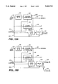
- FIG. 10a is a depiction of a first CARRIER NCO 1 for performing the tracking and carrier phase measurements of the L1 signal.
- FIG. 10b is an illustration of a second CARRIER NCO 2 for performing the tracking and carrier phase measurements of the L2 signal.
- FIG. 11a shows a first CARRIER MIXER 1 for mixing the sampled signal L1 at 420 kHz frequency to 0 HZ frequency.
- FIG. 11b illustrates a second CARRIER MIXER 2 for mixing the sampled signals L2 at 2.6 MHz frequency to 0 HZ frequency.
- FIG. 12a depicts a first CODE MIXER 1 for correlating the L1 signal with a locally generated code (either C/A or P-code).
- FIG. 12b is an illustration of a second CODE MIXER 2 for mixing the L1 Y code with a locally generated version of the P code.
- FIG. 12c is a depiction of a third CODE MIXER 3 for removing the P code from the L2 Y-code and for providing for the L2 code tracking mechanism.
- FIG. 12d shows a fourth CODE MIXER 4 for mixing the estimated L2 W code accumulated across the period of W SYNC 2a signal with the estimated L1 W code accumulated across the period of W SYNC 1 signal.
- FIG. 13a depicts a CODE GENERATOR 1 for generating a local C/A code, a P-code, and a W SYNC 1 signal.
- FIG. 13b is a depiction of a CODE GENERATOR 2 which locally generates a P-code, a W SYNC 2a, and W SYNC 2b signals, wherein the P code is aligned with the incoming L2 satellite signal.
- FIG. 13c illustrates a W SYNC 1, a W SYNC 2a, and W SYNC 2b waveforms.
- FIG. 14a depicts a block CORRELATORS 1 for integrating the early, punctual and late samples of the autocorrelation function of the L1 C/A code (or L1 P code) signal over the period of the L1 C/A EPOCH 1 signal.
- FIG. 14b shows a block CORRELATORS 2 for accumulating correlations at a rate of SCLK if the satellite is not encrypted and a rate W SYNC 2b if encrypted.
- FIG. 15 illustrates a CODE NCO (1 and 2) for providing a clock that drives the CODE GENERATOR (1 and 2 respectively).
- FIG. 16a is a depiction of a DIGITAL SUMMER 1 for accumulating L1 W code estimates over periods given by W SYNC 1.
- FIG. 16b is an illustration of a DIGITAL SUMMER 2 for accumulating the output of CODE MIXER 3 across a period defined by W SYNC 2a.
- FIG. 16c shows a DIGITAL SUMMER ACCUMULATOR that takes the estimated L1 W code samples and accumulates them every SCLK edge for a period given by input W SYNC 1.
- FIG. 17a depicts an ACQUISITION block diagram illustrating the signal acquisition phase of the MICROPROCESSOR SYSTEM.
- FIG. 17b shows a TRACKING block diagram illustrating the signal tracking phase of the MICROPROCESSOR SYSTEM.
- FIG. 18a illustrates a W code profile in frequency domain.
- FIG. 18b shows a W code profile in time domain.
- FIG. 19a depicts an observed W code profile in frequency domain.
- FIG. 19b is an illustration of an observed W code profile in time domain.
- FIG. 1 illustrates a block diagram 10 of the GPS RECEIVER capable of demodulating the satellite signals modulated by the secret W code.
- Each satellite generates different signals and they are processed by different DIGITAL CHANNEL PROCESSORS, which operate exactly the same way.
- FIG. 1 is an overview of the GPS receiver, all elements of which are explained in detail below.
- the GPS ANTENNA may be a magnetically mountable model 21423-00 commercially available from Trimble Navigation of Sunnyvale, Calif.
- the MASTER OSCILLATOR 28 provides the reference oscillator which drives all other clocks in the system.
- the FREQUENCY SYNTHESIZER 18 takes the output of the MASTER OSCILLATOR and generates important clock and local oscillator frequencies used throughout the system.
- a FILTER/LNA 14 performs filtering and low noise amplification of both L1 and L2 signals.
- the noise figure of the RECEIVER system is dictated by the performance of the FILTER/LNA combination.
- the DOWNCONVERTER 16 mixes both L1 and L2 signals in frequency down to approximately 175 MHz and outputs the analogue L1 and L2 signals into an IF PROCESSOR 30.
- the IF PROCESSOR takes the analog L1 and L2 signals at approximately 175 MHz and converts them into the digitally sampled L1 and L2 inphase and quadrature signals at carrier frequencies 420 KHz for L1 and at 2.6 MHz for L2 signals respectively.
- At least one DIGITAL CHANNEL PROCESSORS 32 input the digitally sampled L1 and L2 inphase and quadrature signals. All DIGITAL CHANNEL processors are identical by design and operate on identical input samples. Each DIGITAL CHANNEL PROCESSOR is designed to digitally track the L1 and L2 signals produced by one satellite by tracking code and carrier signals and to perform code and carrier phase measurements in conjunction with the MICROPROCESSOR SYSTEM 34. One DIGITAL CHANNEL PROCESSOR is capable of tracking one satellite in both L1 and L2 channels. MICROPROCESSOR SYSTEM is a general purpose computing device which facilitates tracking and measurements processes, providing pseudorange and carrier phase measurements for a NAVIGATION PROCESSOR 38. The NAVIGATION PROCESSOR performs the higher level function of combining measurements in such a way as to produce position, velocity and time information for the differential and surveying functions.
- the present invention provides for the independent estimate of pseudorange of L2 signal by moving the locally generated L2 P code in time with respect to incoming L2 Y code signal.
- L1 signal provides for the local estimate of W code but is not used for purposes of computation of pseudorange of L2 signal.
- L1 signal is used only for correlation purposes.
- FIG. 2 shows the detailed embodiment of the FILTER/LNA 40.
- Filtered L1 signal 54 and L2 signal 56 are recombined in a POWER COMBINER 58 before being fed into the low noise amplifier LNA 60.
- the output signal 62 represents filtered and amplified L1/L2 signal at 1575.42 MHz and 1227.60 MHz respectively.
- the MASTER OSCILLATOR 70 is depicted in FIG. 3.
- the 5 MHz signal 76 is obtained by dividing the 10 MHz oscillator output signal 72 by 2 in the DIVIDE BY 2 block 74.
- FIG. 4 illustrates the FREQUENCY SYNTHESIZER 80 which takes as an input the 5 MHz signal 82 provided by the MASTER OSCILLATOR and outputs a 1st LO1 signal 90, a 2nd LO2 signal 102, a SCLK signal 100, and a MSEC signal 104; wherein these timing signals are used by different blocks of the GPS RECEIVER.
- the 5 MHz signal 82 is compared with the 5 MHz signal output from a block "DIVIDE BY 5" in a PHASE DETECTOR 84.
- the voltage output from the PHASE DETECTOR represents phase alignment of two 5 MHz signals and includes two signals, wherein the first of these signals has a large phase error and represents a large voltage output; and wherein the second of these signals has a small phase error and represents a small voltage output.
- a LOOP FILTER 86 filters out the high frequency voltage noise signal having a large phase error and outputs the low frequency noise signal 87 having a small phase error which is applied to a voltage controlled oscillator (VCO) 88.
- VCO voltage controlled oscillator
- the low frequency noise signal 87 causes frequency change in the VCO output signal 90.
- the VCO output signal having a 1400 MHz frequency is used as the 1st LO1 (local oscillator) signal.
- a block 92 "DIVIDE BY 8" outputs the 2nd LO2 local oscillator signal 102 having 175 MHz.
- a block 94 "DIVIDE BY 7" divides the LO2 signal and outputs the sampling clock (SCLK) signal 100 having 25 MHz.
- a block 98 "DIVIDE BY 25000" further divides the SCLK signal and outputs the MSEC signal 104 having 1 KHz which is used by the system for measurement of local reference time.
- a "DIVIDE BY 5" block 96 is used to close the LO1 loop.
- the DOWNCONVERTER 110 is depicted in detail in FIG. 5 which decreases the frequency of the L1/L2 signal outputted by the FILTER/LNA.
- the L1 and L2 signals are mixed separately by the 1st LO1 1400 MHz signal 90 (outputted by the FREQUENCY SYNTHESIZER in FIG. 4) in the MIXERs 122 and 124.
- the AMPLIFIERs 134 and 136 respectively amplify the L1 signal 130 and L2 signal 132 and output L1 signal 138 and L2 signal 140.
- FIG. 6 describes an IF (intermediate frequency) PROCESSOR 150 which has as input signals the L1 (175.42 MHz) signal 138 and the L2 (172.4 MHz) signal 140 outputted by the DOWNCONVERTER 110. (See FIG. 5).
- the IF PROCESSOR also uses the 2nd LO2 signal 102 and the SCLK signal 100 outputted by the FREQUENCY SYNTHESIZER 80 (see FIG. 4) as its timing signals.
- the POWERSPLITTERs 142 and 170 split the L1 and the L2 signals into two L1 and L2 signals respectively.
- MSB Most Significant Bit
- the QL1 signal is similarly processed by a LOWPASS FILTER 151, an AMPLIFIER 154, an A/D CONVERTER 158, and a FLIP-FLOP 2 159, wherein the output 166 signal is a digitized QL1 signal at 420 KHz.
- the L2 signal is being processed by a LOWPASS FILTER 176 (178), an AMPLIFIER 180 (182), an A/D CONVERTER 184 (186), and a 188 (190) FLIP-FLOP 3 (4) respectively to produce an inphase version IL2 (quadrature version QL2) of the output signal 192 (194) at 2.6 MHZ.
- the digital output of IF PROCESSOR block are the sampled versions of GPS signal with carrier frequencies of 420 KHz and 2.6 MHZ respectively. The samples include all visible satellite carrier and codes at the respective frequencies.
- a DIGITAL CHANNEL PROCESSOR 200 (the number of channels is equal to the number of satellites that are available for reception by the GPS ANTENNA) given in FIG. 7 includes two main subprocessors: an L1 TRACER 204 and an L2 TRACKER 206 which are controlled by the MICROPROCESSOR SYSTEM 218.
- the inputs represent the digital signals IL1 164, IL2 192, QL1 166, and QL2 194 outputted by the IF PROCESSOR as shown in FIG. 6.
- the timing signals SCLK 100 and MSEC 104 are supplied by the FREQUENCY SYNTHESIZER 80 as depicted in FIG. 4.
- the L1 TRACKER 204 is designed to track L1 C/A code when the encryption is ON and to track L1 P code when the encryption is OFF.
- the L1 TRACKER further develops a signal ⁇ W L1 205 which is sent to the L2 TRACKER.
- the L2 TRACKER 206 is designed to track the optimized enhanced W code cross correlation when encryption is ON and to track L2 P code when encryption is OFF. All signals in each DIGITAL CHANNEL PROCESSOR are clocked synchronously with the sampling clock SCLK 100.
- MSEC signal 104 is used to synchronize each DIGITAL CHANNEL PROCESSOR's measurements to local reference time.
- the MICROPROCESSOR SYSTEM 218 coordinates the performance of the L1 TRACKER and the L2 TRACKER by employing CONTROL signals 216, 214, and 212.
- the LI TRACKER 204 (see FIG. 7) designed for tracking L1 C/A code when encryption is ON and L1 P code when encryption is OFF is given in FIG. 8.
- the principles of the GPS signal tracking and acquisition are described in the article authored by J. J. Spilker and entitled “GPS Signal Structure and Performance Characteristics", pp 47-53, published in Global Positioning System, Vol. I, by The Institute of Navigation, 1980, Alexandria, Va. This article is incorporated herein by reference.
- the RECEIVER can track the received GPS signals having very low signal levels by using a Delay-Lock Loop.
- the essential element of the Delay-Lock Loop is the block 262 CORRELATORS 1, wherein the received code is multiplied by a reference code having a time offset ⁇ T; T being a code chip interval.
- the code correlation is performed at 3 time points (E-early, P-punctual and L-late) on the autocorrelation .function graph.
- the E, P, and L samples of the autocorrelation function are integrated in the block 262 CORRELATOR 1.
- the CORRELATORs 1 output provides an indication of the sign of the delay error of a tracking reference signal.
- This correlation signal in the DIGITAL CHANNEL PROCESSOR becomes a number signal which is used to drive a numerically-controlled oscillator (the block 270 CODE NCO 1) or clock.
- This clock CODE NCO 1 in turn drives the CODE GENERATOR 1 (268) in such a manner that if the clock is lagging in phase, the correction signal drives the clock faster and the reference code speeds up and runs in coincidence with the received signal.
- the reference code is tracking the received code.
- the EPOCH 1 time signal 272 measures the timing of the received signal.
- the RECEIVER also contains a coincident or punctual (P) channel.
- the Delay-Lock-Loop will track the incoming signal. Once the code tracking has been accomplished by the Delay-Lock-Loop, the BPSK satellite signal data at 50 bps can be recovered by the punctual channel (P).
- the satellite signal acquisition should be accomplished before the signal tracking is accomplished.
- the tracking performance discussion of the GPS signals has assumed that somehow the reference code tracking error has been decreased to less than +1 code chip error.
- the user's RECEIVER may have little knowledge of its exact position and there may be a significant uncertainty as to the relative Doppler effect.
- the C/A code there are a limited number, 1023, of code chips in the period; hence even with no initial knowledge of position relative to the satellite, one need only search a maximum of 1023 code chips. If acquisition of the C/A code of one satellite can be accomplished within acquisition time T, then the total acquisition time for 4 satellites can be less than or equal to 4 T if a single RECEIVER is time sequenced over the four satellites.
- the input signals to the L1 TRACKER include the sampled L1 IF signals IL1 (164) and QL1 (166), having frequency of 420 kHz plus Doppler.
- the combination of blocks CARRIER MIXER 1 (246) and CARRIER NCO 1 (244) translates the frequency of the IL1 (164) and QL1 (166) signals to 0 HZ at the I output 252 and Q output 254 of CARRIER MIXER 1.
- CODE MIXER 1 (256) performs code correlation of the L1 signal with a locally generated code Lc (253).
- the locally generated code Lc is selected by the MULTIPLEXER 1 (264) to be either C/A code 263 or P-code (276) (encrypted and non-encrypted operation respectively).
- the local code is provided by the CODE GENERATOR 1 block.
- the C/A or P-code correlation is selected via MULTIPLEXER 1 under the MICROPROCESSOR CONTROL signal.
- the correlated samples are summed (integrated) for an integer multiple of EPOCH 1 signals 272 in the CORRELATORS 1 block.
- CORRELATORS 1 output signals are read by the MICROPROCESSOR system 218 (see also FIG. 7). The MICROPROCESSOR system then processes these values to provide code and carrier feedback mechanisms.
- the output of CARRIER MIXER 1 in Q channel 251 contains an estimate of the L1 Y code when the L1 TRACKER is tracking L1 C/A code.
- the locally generated by the CODE GENERATOR 1, P code (275) is substantially aligned in time with the satellite signal because the L1 TRACKER is tracking the L1 C/A code.
- the locally generated P code 275 is mixed with the Q L1 Y code estimate 251 in CODE MIXER 2 (278).
- the output 277 of CODE MIXER 2 represents an estimate of the L1 W code in a (+/-) 12.5 MHz bandwidth.
- a W SYNC 1 signal 274 generated by the CODE GENERATOR 1 represents a period of 22 L1 P code clocks (see discussion below about the observed W code profile in frequency domain depicted in FIG. 19b).
- the estimate of L1 W code (L1 W) is further processed by a DIGITAL SUMMER 1 block (266).
- the DIGITAL SUMMER 1 accumulates L1 W code estimates over periods given by the W SYNC 1 signal.
- the output of the DIGITAL SUMMER 1 block represents a series of accumulated L1 W code estimates at the rate of W SYNC 1 signal.
- the developed signal ⁇ W L1 (205, see also FIG. 7) is an optimal estimate of an L1 W code bit.
- the signal ⁇ W L1 is sent to the L2 TRACKER block for further processing.
- the L2 TRACKER 206 is illustrated in FIG. 9.
- the L2 TRACKER allows accomplishment of the code and carrier tracking of the L2 satellite signals and to make the code and carrier measurements of the L2 satellite signals.
- the I (305) output of CARRIER MIXER 2 represents an estimate of the L2 Y code.
- the Q channel (306) contains no signal power when the L2 carrier tracking loop is locked.
- the CODE MIXER 3 (310) provides a mechanism for removing the P code from the L2 Y code and provides the L2 code tracking mechanism.
- CODE MIXER 3 develops six outputs (I E , I P , I L , Q E , Q P and Q L ) which are comparisons of the incoming signal (I and Q) with the locally generated P code at three time points (early, punctual, and late). The early and late correlations are used to close the L2 code tracking loop.
- DIGITAL SUMMER 2 The output of CODE MIXER 3 is processed by DIGITAL SUMMER 2 (314). Operation of DIGITAL SUMMER 2 is similar to DIGITAL SUMMER 1. DIGITAL SUMMER 2 accumulates the output of CODE MIXER 3 across a period defined by a W SYNC 2a (326) signal.
- the W SYNC 2a signal is the L2 P code clock divided by 22. (See below more detailed discussion in connection with the observed W code spectrum shown in FIG. 19b).
- the L2 TRACKER generates an L2 P code clock independently of the L1 TRACKER via the CODE NCO 2 (312) and CODE GENERATOR 2 (308) blocks.
- the CODE NCO 2 block is controlled by the L2 code tracking loop such that it drives the CODE. GENERATOR 2 block to produce a locally generated P code which is aligned with the incoming L2 satellite signal.
- the I (346) ( ⁇ I E , ⁇ I P , ⁇ I L ) and Q (348) ( ⁇ Q E , ⁇ Q P and ⁇ Q L ) outputs of the DIGITAL SUMMER 2 represent accumulations, at a rate of W SYNC 2a, of the estimated L2 W code at different time points (early, punctual, and late) on the autocorrelation function of the incoming P(Y) code and the locally generated P code.
- the estimated L2 W code, accumulated across the period W SYNC 2a, ( ⁇ I E , ⁇ I P , ⁇ I L , ⁇ Q E , ⁇ Q P and ⁇ Q L ) are mixed with the estimated L1 W code, accumulated across the period W SYNC 1 ( ⁇ W L1 signal 205) in CODE MIXER 4 (320).
- CODE MIXER 4 outputs in its I channel (350) ⁇ I EW , ⁇ I PW , and ⁇ I LW signals, and in its Q channel (352) ⁇ Q EW , ⁇ Q PW , and ⁇ Q LW signals.
- MULPTIPLEXER 2 (318) provides a mechanism for selecting the output (I E , I P , I L , Q E , Q P and Q L ) of CODE MIXER 3 when the satellite is not encrypted, and the output ( ⁇ I EW , ⁇ I PW , ⁇ I LW , ⁇ Q EW , ⁇ Q PW , and ⁇ Q LW ) of CODE MIXER 4, when the satellite is encrypted.
- CORRELATORS 2 (316) accumulates correlations at a rate of SCLK (100) if the satellite is not encrypted and a rate of W SYNC 2b (322), if the satellite is encrypted.
- the output of CORRELATORS 2 is read into the MICROPROCESSOR SYSTEM 218 at a rate of EPOCH 2 (1 kHz) to form L2 code and carrier tracking feedback values which are applied to CODE NCO 2 and CARRIER NCO 2 respectively.
- FIG. 10a illustrates the CARRIER NCO 1 (244) used in the L1 TRACKER for removing the carrier frequency from the IL1 and QL1 signals.
- This device is described in the article "All-Digital GPS Receiver Mechanization” by Peter Ould and Robert VanWechel, pp. 25-35, “Global Positioning System", Vol. II, The Institute, of Navigation, Alexandria, Va., 1984. This paper is incorporated herein by reference.
- the CARRIER NCO 1 includes a 32-bit ACCUMULATOR 406 which is caused to overflow periodically at the desired output frequency.
- the ACCUMULATOR's L-top bits, L is an integer greater or equal to 1, can be used as the CARRIER NCO 1 output wave for producing a carrier mixing signal used by the CARRIER MIXER 1 (see FIG. 8) for frequency translation.
- the satellite speed is not constant even if the RECEIVER is not movable.
- the RECEIVER's quartz clock is not precise enough and keeps changing all the time. Those are the two main reasons why the frequency of the received satellite signal keeps changing. To accommodate for those changes the MICROPROCESSOR keeps the carrier tracking loop locked by continuously adjusting the frequency word inputted to the CARRIER NCO 1 thus affecting the output.
- Wc is being continuously adjusted by the MICROPROCESSOR SYSTEM to keep the carrier tracking loop locked.
- the MICROPROCESSOR controls the CARRIER NCO 1 frequency by latching in a new frequency word (B1 . . . Bn) in a LATCH 1 (404).
- the frequency word (B1 . . . Bn) is added to the previous CARRIER NCO 1 output sum (Q1 . . . Qn) on each sample clock SCLK (100).
- the L-top bits of the ACCUMULATOR output wave (Q1 . . . Q1) are used as the CARRIER NCO 1 output wave in the I channel (248).
- the first two bits (R1R2) of the carrier Q output signal 250 are generated by a first ADDER 1 (414) by adding two bits (01) (428 and 430) to the two first bits S1(424) and S2 (426) of the CARRIER NCO 1 output signal (S1 . . . Sn).
- FIG. 10b illustrates the CARRIER NCO 2 (see also 300 in FIG. 9) which functions in the same way as the discussed above CARRIER NCO 1.
- the CARRIER MIXER 1 (246) shown in FIG. 11a is used by the L1 TRACKER to perform the frequency translation of the IL1 signal (164) and QL1 signal (166) outputted by the IF PROCESSOR to the baseband frequency signals I (252) and Q (254) using the I (248) and Q (250) output frequency words of the CARRIER NCO 1 according to the standard complex mixing operation:
- FIG. 11b illustrates the CARRIER MIXER 2 (302) employed by the L2 TRACKER to perform the same operation on the L2 signal.
- the CODE MIXER 1 (256 in FIG. 8) depicted in FIG. 12a removes the modulated code from the satellite signal L1 and allows the demodulation of the information contained in the L1 signal.
- the Lc code (253) is selected by the MULTIPLEXER 1 (264) (see FIG. 8) and can be a locally generated by the CODE GENERATOR 1 (268) either C/A code 263 or P code 276.
- the signals I (252) and Q (254) outputted by the CARRIER MIXER 1 are multiplied by the early (480), punctual (482), and late (484) samples of the locally generated code Lc (253).
- MULTIPLIERs (490), (492), (494), (496), (498), and (500) resulting in the early (258,1), punctual (258,2) and late (258,3) samples of the I signal; and in the early (260,1), punctual (260,2) and late (260,3) samples of the Q signal.
- FIG. 12b illustrates the CODE MIXER 2 (278 in FIG. 8), wherein the incoming L1 Y signal 251 is multiplied with the locally generated L1 P code (275) by the MULTIPLIER 502 to produce the W code signal 277.
- the CODE MIXER 3 (310) (see also FIG. 9) shown in FIG. 12c is designed to mix the I (305) and Q (306) versions of the incoming L2 signal with the locally generated L2 P code (332) at three different time points on the autocorrelation function between local and satellite generated L2 P codes.
- the mixing operation is performed by the MULTIPLIER 1 (510) outputting the early I E signal (342,1); by the MULTIPLIER 2 (512) outputting the punctual I P signal (342,2), by the MULTIPLIER 3 (514) outputting the late I L signal (342,3), by the MULTIPLIER 4 (516) outputting the early Q E signal (344,1); by the MULTIPLIER 5 (518) outputting the punctual Q P signal (344,2), and by the MULTIPLIER 6 (520) outputting the late Q L signal (344,3).
- FIG. 12d depicts the CODE MIXER 4 (320) (see also FIG. 9).
- the CODE MIXER 4 is designed to mix the L2 time delayed signals ⁇ I E (346,1), ⁇ I P (346,2), ⁇ I L (346,3), ⁇ Q E (348,1), ⁇ Q P (348,2), and ⁇ Q L (348,3) with the estimated L1 W code bit ( ⁇ W L1 ) (205).
- This operation is performed by the MULTIPLIER 1 (530) outputting the ⁇ I EW signal (350, 1); by the MULTIPLIER 2 (532) outputting the ⁇ I PW signal (350,2); by the MULTIPLIER 3 (534) outputting the ⁇ I LW signal (350,3); by the MULTIPLIER 4 (536) outputting the ⁇ Q EW signal (352, 1); by the MULTIPLIER 5 (538) outputting the ⁇ Q PW signal (352,2); and by the MULTIPLIER 6 (540) outputting the ⁇ Q LW signal (352,3).
- L1 W code instead of perfect, with respect to the signal-to-noise ration (SNR) and timing, locally generated W code introduces a signal to noise disadvantage over the full coded correlation scheme.
- this scheme uses the fundamental 22 Pcode chips period W code clock to optimize the stripping of W code from the L2 signal by the L1 signal.
- This scheme relies on the energy spectrum of the W code signal and does not rely for its optimization on knowing the exact timing of the W code (see detailed discussion below).
- FIG. 13a depicts a detailed diagram of CODE GENERATOR 1 (268).
- the inputs to this block are the CODE NCO 1 output (269) and the MICROPROCESSOR CONTROL signal (212).
- the CODE NCO 1 signal is nominally at the P code rate (10.23 MHz) and is adjusted by the L1 C/A (or P) code tracking loop to maintain lock to the L1 signal.
- the C/A CODE GENERATOR 552 and the P CODE GENERATOR 554 are the standard shift register sequences described in the "Interface Control Document" of Rockwell International Corporation entitled “Navstar GPS Space Segment/Navigation User Interfaces", dated Sep. 26, 1984, as revised Dec.
- the C/A CODE GENERATOR produces signals C/A code (263) and EPOCH 1 (272).
- the C/A code is the locally generated code and EPOCH 1 is the repetition rate of the C/A code (1 kHz).
- the P CODE GENERATOR produces the P code (276).
- the DIVIDE BY N block (558) and the DELAY BY ⁇ block (556) are used to transform the CODE NCO 1 output signal (269) into the W SYNC 1 signal (274), also the DIVIDE BY N block (558) is reset by the EPOCH 1 signal (272).
- W SYNC 1 signal is used as the L1 W code estimate timing signal.
- Both C/A and P CODE GENERATORs can be adjusted under the MICROPROCESSOR CONTROL signal (212) to generate a particular satellite's C/A and P code.
- the DELAY BY ⁇ block (556) introduces no delay
- the DIVIDE BY N block divides the CODE NCO 1 output signal (269) by 22 to generate the W SYNC 1 signal
- the output W SYNC 1 is synchronized to the L1 W code estimate.
- FIG. 13b illustrates the CODE GENERATOR 2 (308). (See also FIG. 9). Operation of the CODE GENERATOR 2 is similar to the disclosed above operation of the CODE GENERATOR 1.
- the clock input from the CODE NCO 2 (328) is controlled by the L2 code tracking loop to keep the P code output (332) of CODE GENERATOR 2 substantially aligned with the L2 P code portion of the L2 Y code.
- the DELAY BY ⁇ block (576) introduces no delay
- the DIVIDE BY N block (578) divides the CODE NCO 2 output signal (328) by 22 to generate the W SYNC 2a (326) and W SYNC 2b (322) signals
- the outputs W SYNC 2a and W SYNC 2b are synchronized to the L2 W code estimate.
- the W SYNC 2b signal is the logical inversion of the W SYNC 2a signal.
- the EPOCH 1 of the CODE GENERATOR 1 is used as the control signal for the block CORRELATORs 1
- the EPOCH 2 and W SYNC 2b signals of the CODE GENERATOR 2 are used as the block CORRELATORs 2 control signals.
- the timing relationship between W SYNC 1, W SYNC 2a, and W SYNC 2b is important in the operation of the optimized cross correlation L2 tracking.
- T iono When mixing L1 and L2 signals in CODE MIXER 4 it is clear that the delay term T iono will affect this mixing process.
- the block CORRELATORs 1 (262) is illustrated in FIG. 14a.
- the function of the CORRELATORS 1 is to integrate the correlated samples IE (inphase early) (258,1), IP (inphase punctual) (258,2), IL (inphase late) (258,3), QE (quadrature early) (260,1), QP (quadrature punctual) (260,2), and QL (quadrature late) (260,3) of the L1 C/A (or P) satellite code with the locally generated version of C/A (or) P code across a time period given by a multiple of C/A EPOCH 1 (272) signals.
- the input sample IE is integrated in an UP/DOWN COUNTER 1 (602) across a period defined by the C/A EPOCH 1 signal, wherein the COUNTER 1 adds if the input is positive and subtracts if it is negative.
- the correlator summations are read by the MICROPROCESSOR (218) using a LATCH 1 (604).
- Each of the IP, IL, QE, QP, and QL samples is similarly integrated by a separate UP/DOWN COUNTER.
- K1 is a L1 code loop gain factor.
- the block CORRELATORS 2 (316 of FIG. 9) is given in FIG. 14b.
- the block CORRELATORs 2 accumulates the result of L2 P code correlation when the satellite is not encrypted and the result of the optimal digital bandwidth compression L2 tracking when the satellite is encrypted.
- the UP/DOWN COUNTER blocks (630-640) accumulate on each SCLK (100) edge.
- the UP/DOWN COUNTER blocks accumulate on each W SYNC 2b (322) edge.
- the clocking choice is made by the MICROPROCESSOR SYSTEM (218) via the MULTIPLEXER 3 (318).
- the output of the CORRELATORs 2 block is read by the MICROPROCESSOR SYSTEM (218) at a rate of EPOCH 2 (1 kHz) (324), a signal developed by CODE GENERATOR 2 (308). These values are then fed back to CODE NCO 2 (312) and CARRIER NCO 2 (300) respectively to close the code and carrier tracking loops.
- the CODE NCO 1 (270 of FIG. 8) given in FIG. 15 provides a clock at 10.23 MHz for the CODE GENERATOR 1 (268) in its NORMAL mode of operation. It can also shift the CODE GENERATOR 1 early or late under the MICROPROCESSOR CONTROL signal 212 by shifting its output phase in its SHIFT (714) mode.
- the CODE NCO 1 output 269 controls the phase of the locally generated codes (P and C/A) and provides the code tracking loop feedback adjustment.
- the CODE NCO 1 includes a 12-bit ADDER (706) and a 12-bit LATCH (708). On each sample clock edge the output of the LATCH is added to the output of the MULTIPLEXER (704).
- the output of the MULTIPLEXER is a 12-bit number N (710) unless Q12 is 1; if Q12 is equal to 1 the output is a 12-bit number M (712).
- the structure and operation of the CODE NCO 2 (3 12 in FIG. 9) is identical to CODE NCO 1.
- FIG. 16a depicts operation of DIGITAL SUMMER 1 (266). (See FIG. 8 for more details). DIGITAL SUMMER 1 accumulates L1 W code estimates (277) over the period W SYNC 1 (274) and outputs this accumulation ⁇ W L1 (205) every W SYNC 1 period.
- DIGITAL SUMMER 2 (314 of FIG. 9) is shown in FIG. 16b.
- DIGITAL SUMMER 2 accumulates L2 W code estimates In (340,1); I P (340,2); I L (340,3); Q E (338,1); Q P (338,2); and Q L (338,3) over the period W SYNC 2a and outputs these accumulations ⁇ I E (346,1); ⁇ I P (346,2); ⁇ I L (346,3); ⁇ Q E (348,1); ⁇ Q P (348,2); and ⁇ Q L (348,3) every W SYNC 2a period (326).
- Both DIGITAL SUMMER 1 and DIGITAL SUMMER 2 blocks use the DIGITAL SUMMER ACCUMULATOR block shown in FIG.
- DIGITAL SUMMER ACCUMULATOR takes the estimated L1 W code samples (277) and accumulates them every SCLK edge (100) for a period by input signal W SYNC 1 (274).
- ADDER 1 (740) and LATCH 1 (742) form the ACCUMULATOR.
- the W SYNC 1 signal latches in the accumulated number into the LATCH 2 (744) to form the output signal ⁇ W L1 .
- the W SYNC 1 signal also clears LATCH 1 in preparation for the next accumulation across the next W SYNC 1 period.
- FIG. 17a illustrates the process of acquisition under encryption.
- the L1 TRACKER is guided by the MICROPROCESSOR SYSTEM to close L1 C/A code and carrier tracking loops.
- This estimate of the L2 carrier frequency from the L1 loop eliminates the requirement for an L2 frequency search, resulting in a potentially narrower L2 carrier tracking loop because the satellite/receiver dynamics are removed from L2 carrier tracking loop.
- a typical L1 carrier tracking loop bandwidth is 10 Hz and the frequency aiding process allows the L2 carrier tracking loop to have a bandwidth of ⁇ 1 Hz.
- This aiding operation in the optimized cross correlation receiver described here is advantageous for two reasons. First, the frequency aiding allows a carrier tracking loop to be closed in the presence of less signal-to-noise ratio (SNR) than that present in full code correlation receivers. Second, with the potential 13.4 dB advantage in SNR over traditional cross correlation methods it allows more effective tracking of ionospheric dynamics between L1 and L2.
- SNR signal-to-noise ratio
- Ionospheric dynamics is dynamics that is not removable by the frequency aiding process and that is due to the changing group and phase delay between L1 and L2 signals.
- a wider loop bandwidth allows more effective tracking of dynamics.
- Traditional cross correlation receivers have an L2 carrier tracking bandwidth of (1/10)-th of a Hz, whereas with the optimized cross correlation an L2 bandwidth of 1 Hz is feasible.
- the next step 754 is to set up P CODE GENERATORS in CODE GENERATORs 1 and 2. With L1 C/A tracking locked there is enough information present to perform a standard P code ⁇ handover ⁇ operation. During this operation, the essentially timing information is used from the L1 C/A code tracking to set up the P CODE GENERATORs in CODE GENERATORs 1 and 2 to be substantially aligned with L1 and L2 satellite generated P codes respectively. The alignment of the P code from CODE GENERATOR 2 with the satellites L2 P code will be corrupted by the ionospheric group delay difference between the L1 and L2 signals. This is the remaining code phase to be searched in order to find L2 signal power.
- the CODE NCO 2 phase output is adjusted (step 756) until power is detected at the output of CORRELATORs 2.
- the MICROPROCESSOR forms three values to look for power in the CORRELATORS 2:
- L2 estimated carrier phase arctan (PQ/PI)
- the L2 carrier tracking loop (step 758) is closed.
- FIG. 17b depicts the signal tracking operation.
- both sets of CORRELATORS L1 and L2 are read by the MICROPROCESSOR system (762).
- the L1 code and carrier tracking loops are formed and the digital voltage feedback signals are applied to the CODE NCO 1 (217) and to the CARRIER NCO 1 (244).
- the next step is the computation of the L2 frequency aiding term (766).
- the following step is the formation of the L2 code and carrier tracking loops and the application of the digital feedback signals to the CODE NCO 2 and to the CARRIER NCO 2 (768).
- the L1 and L2 carrier and code phase measurements are then performed.
- the carrier phase measurements (770) are performed on L1 and L2 by reading the CARRIER NCO 1 and 2 output phase at a chosen MSEC reference time.
- the L1 and L2 code measurements (772) are performed by keeping track in the MICROPROCESSOR of what shifts have been applied to the CODE NCO 1 and 2 respectively.
- a system and a method for optimum correlation processing of L1 and L2 satellite signals which includes an n-bit RECEIVER, n being integer, and at least one n-bit DIGITAL CHANNEL PROCESSOR is also within the scope of the present invention.
- the n-bit RECEIVER comprising an n-bit A/D CONVERTER and the n-bit DIGITAL CHANNEL PROCESSOR reduces quantization noise as compared to the one-bit RECEIVER comprising a one-bit A/D CONVERTER and a one-bit DIGITAL CHANNEL PROCESSOR because the n-bit digital approximation of the sine signals is more precise than the 1-bit approximation.
- FIG. 18a depicts the W code general energy spectrum, wherein F 0 is the first frequency at which the energy of W code is equal to zero.
- the observed W code profile is shown in FIG. 19b, wherein the W period is equal to 22 P(Y) periods, and wherein the C/A EPOCH 1 period is equal to 465 W periods.
- the W code time-profile in general is illustrated in FIG. 18b.
- W code is also synchronized to the C/A code EPOCH 1 and the delay ⁇ is equal to zero.
Abstract
Description
Iout=(QL1)*Q-(IL1)*I; Qout=(IL1)*Q+(QL1)*I.
Claims (80)
Priority Applications (1)
| Application Number | Priority Date | Filing Date | Title |
|---|---|---|---|
| US08/520,332 US5663733A (en) | 1995-08-28 | 1995-08-28 | Digital bandwidth compression for optimum tracking in satellite positioning system receiver |
Applications Claiming Priority (1)
| Application Number | Priority Date | Filing Date | Title |
|---|---|---|---|
| US08/520,332 US5663733A (en) | 1995-08-28 | 1995-08-28 | Digital bandwidth compression for optimum tracking in satellite positioning system receiver |
Publications (1)
| Publication Number | Publication Date |
|---|---|
| US5663733A true US5663733A (en) | 1997-09-02 |
Family
ID=24072148
Family Applications (1)
| Application Number | Title | Priority Date | Filing Date |
|---|---|---|---|
| US08/520,332 Expired - Fee Related US5663733A (en) | 1995-08-28 | 1995-08-28 | Digital bandwidth compression for optimum tracking in satellite positioning system receiver |
Country Status (1)
| Country | Link |
|---|---|
| US (1) | US5663733A (en) |
Cited By (25)
| Publication number | Priority date | Publication date | Assignee | Title |
|---|---|---|---|---|
| US5822429A (en) * | 1996-09-17 | 1998-10-13 | Electro-Radiation Incorporated | System for preventing global positioning satellite signal reception to unauthorized personnel |
| US5889784A (en) * | 1996-02-05 | 1999-03-30 | Hewlett-Packard Company | Predictive failure detection for data storage systems |
| US6067328A (en) * | 1996-12-12 | 2000-05-23 | Alliedsignal | High precision hardware carrier frequency and phase aiding in a GPS receiver |
| US6078290A (en) * | 1998-01-06 | 2000-06-20 | Trimble Navigation Limited | User-controlled GPS receiver |
| US6229857B1 (en) * | 1998-06-02 | 2001-05-08 | Intel Corporation | Adaptive ingress filtering system |
| US6259399B1 (en) * | 1995-10-09 | 2001-07-10 | Snaptrack, Inc. | GPS receivers and garments containing GPS receivers and methods for using these GPS receivers |
| US20030138030A1 (en) * | 2001-08-02 | 2003-07-24 | Stratis Gavnoudias | Configurable terminal engine |
| US6954488B1 (en) | 1999-10-01 | 2005-10-11 | Trimble Navigation Limited | Method and apparatus for improved L2 performance in dual frequency semi-codeless GPS receivers |
| US20050276316A1 (en) * | 1997-11-19 | 2005-12-15 | Alain Rabaeijs | Method and apparatus for receiving GPS/GLONASS signals |
| WO2006030576A1 (en) * | 2004-09-16 | 2006-03-23 | Furuno Electric Co., Ltd. | Code nco and gps receiver |
| US20070165756A1 (en) * | 2006-01-19 | 2007-07-19 | Commissariat A L'energie Atomique | Signals reception chain |
| US20080158050A1 (en) * | 2006-12-27 | 2008-07-03 | Sharon Levy | Method for acquisition of gps signals and gps receiver with sample time error and frequency offset compensation |
| WO2008085220A2 (en) | 2006-10-19 | 2008-07-17 | Datagrid, Inc. | L1/l2 gps receiver with programmable logic |
| US20080240309A1 (en) * | 2007-03-30 | 2008-10-02 | Zhike Jia | Efficient and flexible numerical controlled oscillators for navigational receivers |
| WO2011054225A1 (en) * | 2009-11-09 | 2011-05-12 | 上海华测导航技术有限公司 | Baseband circuit structure for realizing dual-frequency global positioning system (gps) satellite signal receiver and method thereof |
| US20110309978A1 (en) * | 2009-02-27 | 2011-12-22 | Furuno Electric Co., Ltd. | Gnss receiver |
| US20130028595A1 (en) * | 2010-04-16 | 2013-01-31 | Nippon Telegraph And Telephone Corporation | Frequency offset estimating method and frequency offset estimating apparatus |
| US8369967B2 (en) | 1999-02-01 | 2013-02-05 | Hoffberg Steven M | Alarm system controller and a method for controlling an alarm system |
| US20140104103A1 (en) * | 2012-10-16 | 2014-04-17 | Per K. Enge | Server algorithms to improve space based authentication |
| US8892495B2 (en) | 1991-12-23 | 2014-11-18 | Blanding Hovenweep, Llc | Adaptive pattern recognition based controller apparatus and method and human-interface therefore |
| US20140354474A1 (en) * | 2013-05-29 | 2014-12-04 | The Boeing Company | Determining Ionospheric Time Delays for Global Positioning System (GPS) Receivers Using Multiple Carrier Frequencies |
| EP3282287A1 (en) * | 2016-08-11 | 2018-02-14 | Airbus Defence and Space GmbH | Improvement of receiving spread spectrum signals |
| CN109633714A (en) * | 2018-12-26 | 2019-04-16 | 西安空间无线电技术研究所 | A kind of L2P(Y of high W code adaptability) signal trace method |
| US10361802B1 (en) | 1999-02-01 | 2019-07-23 | Blanding Hovenweep, Llc | Adaptive pattern recognition based control system and method |
| WO2023129763A1 (en) * | 2021-12-30 | 2023-07-06 | Deere & Company | Satellite navigation receiver with aggregate channel digital baseband processing |
Citations (1)
| Publication number | Priority date | Publication date | Assignee | Title |
|---|---|---|---|---|
| US5541606A (en) * | 1995-02-02 | 1996-07-30 | Trimble Navigation Limited | W-code enhanced cross correlation satellite positioning system receiver |
-
1995
- 1995-08-28 US US08/520,332 patent/US5663733A/en not_active Expired - Fee Related
Patent Citations (1)
| Publication number | Priority date | Publication date | Assignee | Title |
|---|---|---|---|---|
| US5541606A (en) * | 1995-02-02 | 1996-07-30 | Trimble Navigation Limited | W-code enhanced cross correlation satellite positioning system receiver |
Cited By (47)
| Publication number | Priority date | Publication date | Assignee | Title |
|---|---|---|---|---|
| US8892495B2 (en) | 1991-12-23 | 2014-11-18 | Blanding Hovenweep, Llc | Adaptive pattern recognition based controller apparatus and method and human-interface therefore |
| US6259399B1 (en) * | 1995-10-09 | 2001-07-10 | Snaptrack, Inc. | GPS receivers and garments containing GPS receivers and methods for using these GPS receivers |
| US5889784A (en) * | 1996-02-05 | 1999-03-30 | Hewlett-Packard Company | Predictive failure detection for data storage systems |
| US5822429A (en) * | 1996-09-17 | 1998-10-13 | Electro-Radiation Incorporated | System for preventing global positioning satellite signal reception to unauthorized personnel |
| US6067328A (en) * | 1996-12-12 | 2000-05-23 | Alliedsignal | High precision hardware carrier frequency and phase aiding in a GPS receiver |
| US20060098721A1 (en) * | 1997-11-19 | 2006-05-11 | Alain Rabaeijs | Method and apparatus for receiving GPS/GLONASS signals |
| US20050276316A1 (en) * | 1997-11-19 | 2005-12-15 | Alain Rabaeijs | Method and apparatus for receiving GPS/GLONASS signals |
| US6078290A (en) * | 1998-01-06 | 2000-06-20 | Trimble Navigation Limited | User-controlled GPS receiver |
| US6384777B1 (en) | 1998-01-06 | 2002-05-07 | Trimble Navigation Limited | User-controlled GPS receiver |
| US6229857B1 (en) * | 1998-06-02 | 2001-05-08 | Intel Corporation | Adaptive ingress filtering system |
| US8369967B2 (en) | 1999-02-01 | 2013-02-05 | Hoffberg Steven M | Alarm system controller and a method for controlling an alarm system |
| US10361802B1 (en) | 1999-02-01 | 2019-07-23 | Blanding Hovenweep, Llc | Adaptive pattern recognition based control system and method |
| US9535563B2 (en) | 1999-02-01 | 2017-01-03 | Blanding Hovenweep, Llc | Internet appliance system and method |
| US6954488B1 (en) | 1999-10-01 | 2005-10-11 | Trimble Navigation Limited | Method and apparatus for improved L2 performance in dual frequency semi-codeless GPS receivers |
| US7139305B2 (en) * | 2001-08-02 | 2006-11-21 | Infineon Technologies Ag | Configurable terminal engine |
| US20030138030A1 (en) * | 2001-08-02 | 2003-07-24 | Stratis Gavnoudias | Configurable terminal engine |
| US20070263701A1 (en) * | 2004-09-16 | 2007-11-15 | Furuno Electric Company, Ltd. | Code Nco and Gps Receiver |
| WO2006030576A1 (en) * | 2004-09-16 | 2006-03-23 | Furuno Electric Co., Ltd. | Code nco and gps receiver |
| US7573337B2 (en) | 2004-09-16 | 2009-08-11 | Furuno Electric Company, Ltd. | Code NCO and GPS receiver |
| US7929641B2 (en) * | 2006-01-19 | 2011-04-19 | Commissariat A L'energie Atomique | Signals reception chain |
| US20070165756A1 (en) * | 2006-01-19 | 2007-07-19 | Commissariat A L'energie Atomique | Signals reception chain |
| CN101606079B (en) * | 2006-10-19 | 2013-05-29 | 数据栅格公司 | L1/l2 GPS receiver with programmable logic |
| WO2008085220A2 (en) | 2006-10-19 | 2008-07-17 | Datagrid, Inc. | L1/l2 gps receiver with programmable logic |
| WO2008085220A3 (en) * | 2006-10-19 | 2009-01-08 | Datagrid Inc | L1/l2 gps receiver with programmable logic |
| RU2453867C2 (en) * | 2006-10-19 | 2012-06-20 | Датагрид, Инк. | Gps receiver (versions) and method to extract amplitude and pseudo-doppler signal phase |
| US8665151B2 (en) | 2006-10-19 | 2014-03-04 | Datagrid, Inc. | L1/L2 GPS receiver with programmable logic |
| US7773034B2 (en) * | 2006-12-27 | 2010-08-10 | Intel Corporation | Method for acquisition of GPS signals and GPS receiver with sample time error and frequency offset compensation |
| CN101568851B (en) * | 2006-12-27 | 2012-12-26 | 英特尔公司 | Method for acquisition of GPS signals and GPS receiver with sample time error and frequency offset compensation |
| US20080158050A1 (en) * | 2006-12-27 | 2008-07-03 | Sharon Levy | Method for acquisition of gps signals and gps receiver with sample time error and frequency offset compensation |
| US20080240309A1 (en) * | 2007-03-30 | 2008-10-02 | Zhike Jia | Efficient and flexible numerical controlled oscillators for navigational receivers |
| US7830951B2 (en) * | 2007-03-30 | 2010-11-09 | Sirf Technology Holdings, Inc. | Efficient and flexible numerical controlled oscillators for navigational receivers |
| US8692714B2 (en) * | 2009-02-27 | 2014-04-08 | Furuno Electric Company Limited | GNSS receiver |
| US20110309978A1 (en) * | 2009-02-27 | 2011-12-22 | Furuno Electric Co., Ltd. | Gnss receiver |
| WO2011054225A1 (en) * | 2009-11-09 | 2011-05-12 | 上海华测导航技术有限公司 | Baseband circuit structure for realizing dual-frequency global positioning system (gps) satellite signal receiver and method thereof |
| US20130028595A1 (en) * | 2010-04-16 | 2013-01-31 | Nippon Telegraph And Telephone Corporation | Frequency offset estimating method and frequency offset estimating apparatus |
| US8855485B2 (en) * | 2010-04-16 | 2014-10-07 | Nippon Telegraph And Telephone Corporation | Frequency offset estimating method and frequency offset estimating apparatus |
| US20140104103A1 (en) * | 2012-10-16 | 2014-04-17 | Per K. Enge | Server algorithms to improve space based authentication |
| US8837728B2 (en) * | 2012-10-16 | 2014-09-16 | The Boeing Company | Server algorithms to improve space based authentication |
| US10728032B2 (en) | 2012-10-16 | 2020-07-28 | The Boeing Company | Server algorithms to improve space based authentication |
| GB2518707A (en) * | 2013-05-29 | 2015-04-01 | Boeing Co | Determining ionospheric time delays for global positioning system (GPS) receivers using multiple carrier frequencies |
| GB2518707B (en) * | 2013-05-29 | 2016-03-02 | Boeing Co | Determining ionospheric time delays for global positioning system (GPS) receivers using multiple carrier frequencies |
| US20140354474A1 (en) * | 2013-05-29 | 2014-12-04 | The Boeing Company | Determining Ionospheric Time Delays for Global Positioning System (GPS) Receivers Using Multiple Carrier Frequencies |
| US11061142B2 (en) * | 2013-05-29 | 2021-07-13 | The Boeing Company | Determining ionospheric time delays for global positioning system (GPS) receivers using multiple carrier frequencies |
| EP3282287A1 (en) * | 2016-08-11 | 2018-02-14 | Airbus Defence and Space GmbH | Improvement of receiving spread spectrum signals |
| US10177950B2 (en) | 2016-08-11 | 2019-01-08 | Airbus Ds Gmbh | Receiving spread spectrum signals |
| CN109633714A (en) * | 2018-12-26 | 2019-04-16 | 西安空间无线电技术研究所 | A kind of L2P(Y of high W code adaptability) signal trace method |
| WO2023129763A1 (en) * | 2021-12-30 | 2023-07-06 | Deere & Company | Satellite navigation receiver with aggregate channel digital baseband processing |
Similar Documents
| Publication | Publication Date | Title |
|---|---|---|
| US5541606A (en) | W-code enhanced cross correlation satellite positioning system receiver | |
| US5663733A (en) | Digital bandwidth compression for optimum tracking in satellite positioning system receiver | |
| US5621416A (en) | Optimized processing of signals for enhanced cross-correlation in a satellite positioning system receiver | |
| US5805108A (en) | Apparatus and method for processing multiple frequencies in satellite navigation systems | |
| US5825887A (en) | Transmitting and receiving apparatus for full code correlation operation under encryption for satellite positioning system | |
| US5610984A (en) | Optimal L2 tracking in a SPS receiver under encryption without knowledge of encryption timing characteristics | |
| US5923287A (en) | Combined GPS/GLONASS satellite positioning system receiver | |
| EP0420329B1 (en) | P-code-aided global positioning system receiver | |
| US5689271A (en) | Method and apparatus for civilian receiver operation with P(Y) code in satellite positioning system receiver | |
| US5576715A (en) | Method and apparatus for digital processing in a global positioning system receiver | |
| US5535278A (en) | Global positioning system (GPS) receiver for recovery and tracking of signals modulated with P-code | |
| US5903654A (en) | Method and apparatus for eliminating ionospheric delay error in global positioning system signals | |
| US5192957A (en) | Sequencer for a shared channel global positioning system receiver | |
| US6061390A (en) | P-code enhanced method for processing encrypted GPS signals without knowledge of the encryption code | |
| US6069583A (en) | Receiver for a navigation system, in particular a satellite navigation system | |
| US5600670A (en) | Dynamic channel allocation for GPS receivers | |
| US6707843B2 (en) | Strong signal cancellation to enhance processing of weak spread spectrum signal | |
| AU715461B2 (en) | Dual frequency global positioning system | |
| CA2298213C (en) | Receiver calibration technique for global orbiting navigation satellite system (glonass) | |
| CA2061067C (en) | Global positioning system receiver digital processing technique | |
| US5949372A (en) | Signal injection for calibration of pseudo-range errors in satellite positioning system receivers | |
| Dong | IF GPS signal simulator development and verification | |
| US5850420A (en) | Wideband receiver for the measurement of distance by pseudo-random code signals | |
| US6154170A (en) | Enhanced attitude determination system using satellite navigation receiver with antenna multiplexing | |
| Braasch et al. | Tutorial: GPS receiver architectures, front-end and baseband signal processing |
Legal Events
| Date | Code | Title | Description |
|---|---|---|---|
| FEPP | Fee payment procedure |
Free format text: PAYOR NUMBER ASSIGNED (ORIGINAL EVENT CODE: ASPN); ENTITY STATUS OF PATENT OWNER: LARGE ENTITY |
|
| AS | Assignment |
Owner name: ABN AMRO BANK N.V., AS AGENT, ILLINOIS Free format text: SECURITY AGREEMENT;ASSIGNOR:TRIMBLE NAVIGATION LIMITED;REEL/FRAME:010996/0643 Effective date: 20000714 |
|
| FPAY | Fee payment |
Year of fee payment: 4 |
|
| FPAY | Fee payment |
Year of fee payment: 8 |
|
| AS | Assignment |
Owner name: TRIMBLE NAVIGATION LIMITED, CALIFORNIA Free format text: RELEASE OF SECURITY INTEREST;ASSIGNOR:ABN AMRO BANK N.V.;REEL/FRAME:016345/0177 Effective date: 20050620 |
|
| REMI | Maintenance fee reminder mailed | ||
| LAPS | Lapse for failure to pay maintenance fees | ||
| STCH | Information on status: patent discontinuation |
Free format text: PATENT EXPIRED DUE TO NONPAYMENT OF MAINTENANCE FEES UNDER 37 CFR 1.362 |
|
| FP | Lapsed due to failure to pay maintenance fee |
Effective date: 20090902 |