US5650816A - Correction of film instability based on movement of the video image - Google Patents
Correction of film instability based on movement of the video image Download PDFInfo
- Publication number
- US5650816A US5650816A US08/148,398 US14839893A US5650816A US 5650816 A US5650816 A US 5650816A US 14839893 A US14839893 A US 14839893A US 5650816 A US5650816 A US 5650816A
- Authority
- US
- United States
- Prior art keywords
- scan
- image
- unsteadiness
- signal
- video image
- Prior art date
- Legal status (The legal status is an assumption and is not a legal conclusion. Google has not performed a legal analysis and makes no representation as to the accuracy of the status listed.)
- Expired - Lifetime
Links
Images

Classifications
-
- H—ELECTRICITY
- H04—ELECTRIC COMMUNICATION TECHNIQUE
- H04N—PICTORIAL COMMUNICATION, e.g. TELEVISION
- H04N3/00—Scanning details of television systems; Combination thereof with generation of supply voltages
- H04N3/36—Scanning of motion picture films, e.g. for telecine
-
- H—ELECTRICITY
- H04—ELECTRIC COMMUNICATION TECHNIQUE
- H04N—PICTORIAL COMMUNICATION, e.g. TELEVISION
- H04N5/00—Details of television systems
- H04N5/222—Studio circuitry; Studio devices; Studio equipment
- H04N5/253—Picture signal generating by scanning motion picture films or slide opaques, e.g. for telecine
Definitions
- This invention relates to the measurement and correction of film instability which occurs in film scanning equipment which converts between images stored on film and images represented as video signals.
- the invention is particularly applicable to telecine which converts film images to video signals and may also be applied to cameras.
- GB-A-2165417 (British Broadcasting Corporation) proposes the use of motion vectors in film unsteadiness correction.
- a motion vector measurement derives displacement signals from the input video signal which represent the horizontal and vertical displacement of successive film frames.
- the output signal is formed by a two-dimensional interpolator under the control of a control circuit in dependence upon the displacement signals. Pans, zooms, shot changes and other global measurements are detected by an exception detector which inhibits the output of the interpolation control to prevent spurious misregistration information.
- Block matching in which the sum of the absolute values of the differences between the present data and the data from the previous field or frame is computed for a two dimensional block of data. This process is performed with the reference block offset by one or more pixels or lines and the offset which gives the minimum sum is taken to be the motion vector.
- phase correlation which involves a double Fourier Transform and is thought to give more reliable results than 1. above.
- the two techniques may be combined.
- An example of phase correlation may be found in a paper by Pearson, J. J., Hines, D. C., Goldman, S. and Kuglin, C. D. entitled ⁇ Video Rate Image Correlation Processor ⁇ , S.P.I.E. Vol. 119 Application of Digital Image Processing (IOCC 1977).
- An example of methods 1) and 2) combined is given in WO 87/04033 (British Broadcasting Corporation).
- GB-A-2165417 referred to previously estimates motion by Taylor Expansion, using a truncated Taylor expansion of the frame difference based on a paper by Netravali, A. N. and Robbins, J. D. entitled ⁇ Motion-Compensated Television Coding: Part 1 ⁇ . B.S.T.J., Vol. 58, No. 3, March 1979. This technique can be considered to be a form of 3. above.
- the main advantage of measuring the picture signal rather than sprocket holes or other techniques of film registration is that the measurement is a true indication of the resultant picture unsteadiness.
- difficulties specific to unsteadiness compensation which arise if the camera or scanner should pan around the image, or if objects within the image are moving.
- Special techniques must be used to prevent the compensator from attempting to cancel any such movements.
- the present invention aims to improve on existing techniques for applying motion vectors to film unsteadiness correction.
- the invention when applied to a flying spot telecine generates a movement signal from the picture signal and applies this to the cathode ray tube scan.
- Embodiments of the invention have the advantage that more accurate correction of small sub-pixel movements is possible with scan correction than with prior art systems which use the motion signal as a correcting signal to the addressing circuitry of a frame store.
- a prescan of each film frame is performed solely to measure positional errors and is followed by a corrected telecine scan.
- a system using continuous correction during the film is used, compensating for film motion faster than frame rate. Both alternatives have the advantage of avoiding a one frame delay in telecine scan shift correction which would occur if compensation were derived from one scanned frame and applied to the next.
- measurement of motion detects only the direction of motion. Correction feedback is then relied on to reduce the amplitude of the error to zero. Preferably a limited range of correction is imposed to reduce the effect of false corrections caused by global variations such as camera pan etc. Preferably, only the most frequently occuring corrections are used reducing the effect of false corrections due to moving objects within the picture.
- FIG. 1 is a simple block diagram of a flying spot telecine having an unsteadiness compensation system operating on the scan generation control;
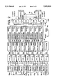
- FIG. 2 is a schematic block diagram of a movement compensator embodying the invention and suitable for use with the embodiments of FIGS. 1 and 2.
- a flying spot telecine such as the Ursa (RTM) telecine manufactured and sold by Rank Cintel Limited of Ware, Hertfordshire, England.
- RTM Ursa
- the invention is also applicable to other flying spot telecine and other types of telecine such as camera tube telecine, line array and area array telecine and cameras.
- a cathode ray tube (CRT) scanner 10 produces a raster scan 12 which is focussed by lens 14 onto cinematographic film 16.
- the scan is produced by vertical and horizontal deflection coils 18 under the control of digital scan generator 20 whose output is amplified by scan amplifier 22 prior to application to the defection coils.
- digital scan generator 20 whose output is amplified by scan amplifier 22 prior to application to the defection coils.
- the scan is usually a sequential raster scan, the position of the scan on the CRT faceplate and the nature of the scan may be varied by suitable control of the scan generator 20.
- Signal detectors 24 Light transmitted through the film on scanning is detected by signal detectors 24. These detectors are conventionally separate red, green and blue photo-multiplier tubes.
- the analog R, G, B video signals are converted into digital signals and then processed separately by signal processor 26 before conversion into an interlaced signal in frame store 28.
- the signal is output in any desired form, such as digital 4:2:2, Y Cr or RGB for recording or transmission.
- the signal processing stage 26 applies a number of corrections to the signal, such as aperture correction, afterglow correction, primary and secondary colour correction.
- the R, G, B signal is split after analog-to-digital conversion of the photo-multiplier output of the signal detectors 24.
- One signal path processes the signal in the normal manner described whereas the other path forms the input to movement compensator 30, the output of which provides horizontal and vertical scan shift controls for the scan generator 20.
- any known motion vector measurement may be employed with the system of FIG. 1 to detect the degree and direction of motion of images represented by a video signal. This measure of movement is then applied as a correction signal to the scan circuitry of the flying spot film scanner. This technique allows more accurate correction of small sub-pixel movements than a system which uses the detected movement as a correction signal for the addressing of a frame store to compensate for that motion. This latter type of system is employed in GB-A-2165417 discussed previously.
- the method of correction described would always result in the scan shift being applied one frame too late. This may be avoided by introducing a prescan which scans the film image only to measure the positional errors and is immediately followed by the normal, but corrected, telecine scan. As an alternative, a system using continuous correction during the frame could be used, compensating for film motion at a rate higher than the frame rate.
- the method described could be simplified by only detecting the direction of motion, and not its degree, and relying on the correction feedback to reduce the amplitude of the error to zero.
- a limited range of correction is necessary to reduce the effect of false corrections prompted by global changes in the picture caused, by example, by panning or scene shifting. Using only the most frequently occuring correlations reduces the effect of false corrections due to moving objects within the picture.
- the movement compensator 30 measures the direction only of the picture movement since the previous frame.
- the horizontal (X) and vertical (Y) correction signals are increased or decreased to move the scans in the same direction as the film. This process of measurement and correction is continued during the frame until the relative movement of the film and scans is zero. Subsequently, the movement of the film is tracked by the scans to provide a stable picture image.
- the algorithm chosen to measure the picture movement is as follows.
- P n pixel data from one of 8 (n) spatially surrounding pixels
- the movement compensator circuit operates as follows:
- the video input signal to the movement compensation circuit is fed to a series of delays 32a-j each arranged to provide eight signals which spatially surround a ⁇ present time ⁇ pixel. Each of these signals is subtracted from the present time signal delayed through 1 line and one pixel delay 32e by an arithmetic logic unit 34a-j.
- the relative delays may be appreciated by considering a block of 9 pixels a-j as follows:
- an additional alu. 34k is provided which subtracts the present time pixel from its counterpart in the previous frame which is provided by delaying the present time delay 32(e) of 1 line +1 pixel by a further 1 frame delay in delay element 32k.
- the output of the arithmetic unit 34k which represents the inter-frame difference for the centre pixel, is fed to a programmable read only memory device PROM 40 which outputs the reciprocal of the input from its look-up table.
- the outputs of the other alus 34a-j which represent the difference between the present time pixel and each of the neighbouring pixels are fed each to a respective multiplier 36a-j in which the (a-b) input from the alu 34 is multiplied by the reciprocal output from PROM 40.
- This operation effectively divides the spatial difference signals by the temporal difference.
- the scaling of the signals to the multipliers 36 is chosen such that the output m.s.b. is only true when the output signal exceeds 1.0.
- the number of pixels giving a true (1.0) result is counted for each of the eight spatial offsets using counters 38a-j and the first one to reach a maximum count gives the appropriate output pulse, corresponding to the spatial frequency offset with the most frequent true results, and resets all counters by outputting a logical high to eight input OR gate 42 whose output is coupled to the reset pins of each counter 38.
- the counter output pulse is then decoded by the OR gates 44a-d to increment or decrement the appropriate combination of the output X shift and output Y shift up-down counters 46 X, Y the output signal of which is fed to the scan generation circuitry 20 of FIG. 1.
- counters 38a-c correspond to the top left, top middle and top right pixels surrounding the present time pixel; counters 38d, f to the middle left and middle right; and counters 38g-j to the bottom left, bottom middle and bottom right, respectively.
- a true output from any of the three top row counters will increment the Y shift counter 46Y upwards whereas a true output from any of the bottom row counters will increment the Y shift count downwards.
- a true count from any of the left hand row a, d, g counters will increment the X counter 46X up and a true output from the left hand row c, f, j will increment X counter 46X downwards.
- the outputs from these up-down counters 46X, Y are added to the scan shifts generated by the scan generator 20 in such a direction as to compensate for the film unsteadiness. If, for example, the film moves slightly to the left then the fourth counter from the top will be enabled and after 16 clocks (assuming a 4 bit counter) will give an up count pulse to the X shift counter causing the scans to move very slightly in the same direction as the film and to reduce the next measurement.
- the circuit is therefore desirably unable to follow faster movements (greater than about 1 pixel per frame perhaps) such as might be due to picture object movement or camera pans, and would not react quick enough to cause local geometric picture distortions.
- the amount of movement due to one output counter step is arranged to be imperceptible to the eye and yet is more than the film would move between measurement results (i.e. in a 16 clock interval).
- the counters would be getting random enables and would take longer to reach maximum count, the one which happens to give an output pulse causes the scans to move which would ensure that the next output pulse is in the opposite direction, and maintain an average steady scan position, the pulse to pulse movement being too small to detect.
- the range of the output correction signals is limited to a small amount equivalent to the maximum expected film movement (perhaps ⁇ 4 pixels), thereby ensuring that the scans are not shifted significantly due to prolonged picture movement such as a camera pan.
- the 8 counters 38a-j are assumed to be 4 bit counters having a total count of 16.
- the total count can be chosen to optimise the performance.
- Another example would be to have a total count of say 1024 (10 bit counters) which is similar to the number of samples in a video line.
- the output pulse would correspond to the spatial offset with the most frequent true values over about one line of the scan. This will help to avoid false corrections from moving objects within the picture because they will generally be of less than a half line in width.
- the total count does not need to be an exact power of 2 nor does it need to be related to the numbers of pixels in a line.
- One problem which can arise from the embodiments described is the effect of the picture edge or blanking information. This may be overcome by producing an extended blanking or masking signal which can be applied to inhibit the counters when the scan is near or beyond the edge of the picture.
- a camera tube embodiment would operate in a manner similar to that illustrated in FIG. 1.
- the cathode ray tube is replaced with a light source and the photomultiplier tubes (signal detectors 24 in FIG. 1) replaced by camera tubes or by a single camera tube in the case of a single tube monochrome camera.
- the frame store is discarded.
- the scan amplifier then feeds the camera tubes rather than the CRT.
- the cathode ray tube is replaced by a light source and the photomultiplier tubes by line array CCD sensors.
- the scan generators and amplifiers are replaced by timing circuits feeding the CCD sensors.
- the CCD example operates in a slightly different manner. Rather than moving the scan position, the movement compensator adjusts for vertical picture displacement by advancing or delaying the time at which each line scan of the CCD sensor is initiated. By delaying the start of the scan the film image will have moved further due to its constant motion.
- One disadvantage of this method is that timing changes will cause fluctuations of picture brightness due to variations in the time for which light is applied to the sensor. This problem can be overcome by measuring the application time for each line and dividing the video signal by this value. Horizontal picture displacement may be similarly compensated by adjusting the relative timing between the CCD sensor scan initiation and the A to D conversion and video store writing pulses.
- Pre-scanning a frame of film as described previously would only work if two sets of line array sensors were used. The spacing of these would have to be determined accurately and problems would arise with variable film speed operation. A solution to these problems would be to prescan each line rather than each frame.
Landscapes
- Engineering & Computer Science (AREA)
- Multimedia (AREA)
- Signal Processing (AREA)
- Details Of Television Scanning (AREA)
- Facsimile Scanning Arrangements (AREA)
Abstract
Description
______________________________________
a                b     c
d                e     f
g                h     j
______________________________________
______________________________________
0              1p           2p
1L             1L + 1p      1L + 2p
2L             2L + 1p      2L + 2p
______________________________________
Claims (24)
Applications Claiming Priority (2)
| Application Number | Priority Date | Filing Date | Title |
|---|---|---|---|
| GB9223442A GB2272595B (en) | 1992-11-09 | 1992-11-09 | Measurement and correction of film instability |
| GB9223442 | 1992-11-09 |
Publications (1)
| Publication Number | Publication Date |
|---|---|
| US5650816A true US5650816A (en) | 1997-07-22 |
Family
ID=10724766
Family Applications (1)
| Application Number | Title | Priority Date | Filing Date |
|---|---|---|---|
| US08/148,398 Expired - Lifetime US5650816A (en) | 1992-11-09 | 1993-11-08 | Correction of film instability based on movement of the video image |
Country Status (2)
| Country | Link |
|---|---|
| US (1) | US5650816A (en) |
| GB (1) | GB2272595B (en) |
Cited By (6)
| Publication number | Priority date | Publication date | Assignee | Title |
|---|---|---|---|---|
| US6091446A (en) * | 1992-01-21 | 2000-07-18 | Walker; Bradley William | Consecutive frame scanning of cinematographic film |
| EP0893914A3 (en) * | 1997-07-24 | 2002-01-02 | Nikon Corporation | Image processing method, image processing apparatus, and storage medium for storing control process |
| US20030030812A1 (en) * | 2001-05-24 | 2003-02-13 | Eastman Kodak Company | Apparatus and method to measure film motion in a film gate |
| US20040028136A1 (en) * | 2000-10-06 | 2004-02-12 | Thomas Leonard | Device for correcting still image errors in a video signal |
| US6775419B2 (en) | 1997-07-24 | 2004-08-10 | Nikon Corporation | Image processing method, image processing apparatus, and storage medium for storing control process |
| EP3393116A1 (en) | 2017-04-21 | 2018-10-24 | Blackmagic Design Pty Ltd | Film scanner |
Families Citing this family (1)
| Publication number | Priority date | Publication date | Assignee | Title |
|---|---|---|---|---|
| DE19536691B4 (en) * | 1995-09-30 | 2008-04-24 | Bts Holding International B.V. | Method and device for correcting image frame errors in television filming |
Citations (4)
| Publication number | Priority date | Publication date | Assignee | Title |
|---|---|---|---|---|
| US3780222A (en) * | 1971-03-12 | 1973-12-18 | Evr Enterprises | Electronic weave compensation |
| US4897729A (en) * | 1988-03-07 | 1990-01-30 | Rank Cintel Limited | Telecine with electronically variable raster to produce picture effects |
| US5179314A (en) * | 1990-09-19 | 1993-01-12 | Walker David L | Non-sequential raster scanning apparatus and method |
| US5475423A (en) * | 1992-12-10 | 1995-12-12 | U.S. Philips Corporation | Film scanner which doubly scans to correct for film speed and position errors |
Family Cites Families (4)
| Publication number | Priority date | Publication date | Assignee | Title |
|---|---|---|---|---|
| US4823204A (en) * | 1987-06-18 | 1989-04-18 | Image Transform | Method and apparatus for film weave correction |
| DE3736790A1 (en) * | 1987-10-30 | 1989-05-11 | Broadcast Television Syst | METHOD FOR AUTOMATICALLY CORRECTING IMAGE ERRORS IN FILM SCANNING |
| WO1991006181A1 (en) * | 1989-10-20 | 1991-05-02 | Walker Digital Audio Video Systems, Inc. | Real time registration weave correction system |
| GB2244884B (en) * | 1990-05-21 | 1994-02-23 | Rank Cintel Ltd | Electronic film positioning |
-
1992
- 1992-11-09 GB GB9223442A patent/GB2272595B/en not_active Expired - Fee Related
-
1993
- 1993-11-08 US US08/148,398 patent/US5650816A/en not_active Expired - Lifetime
Patent Citations (4)
| Publication number | Priority date | Publication date | Assignee | Title |
|---|---|---|---|---|
| US3780222A (en) * | 1971-03-12 | 1973-12-18 | Evr Enterprises | Electronic weave compensation |
| US4897729A (en) * | 1988-03-07 | 1990-01-30 | Rank Cintel Limited | Telecine with electronically variable raster to produce picture effects |
| US5179314A (en) * | 1990-09-19 | 1993-01-12 | Walker David L | Non-sequential raster scanning apparatus and method |
| US5475423A (en) * | 1992-12-10 | 1995-12-12 | U.S. Philips Corporation | Film scanner which doubly scans to correct for film speed and position errors |
Cited By (10)
| Publication number | Priority date | Publication date | Assignee | Title |
|---|---|---|---|---|
| US6091446A (en) * | 1992-01-21 | 2000-07-18 | Walker; Bradley William | Consecutive frame scanning of cinematographic film |
| EP0893914A3 (en) * | 1997-07-24 | 2002-01-02 | Nikon Corporation | Image processing method, image processing apparatus, and storage medium for storing control process |
| US6775419B2 (en) | 1997-07-24 | 2004-08-10 | Nikon Corporation | Image processing method, image processing apparatus, and storage medium for storing control process |
| US20040028136A1 (en) * | 2000-10-06 | 2004-02-12 | Thomas Leonard | Device for correcting still image errors in a video signal |
| US7116720B2 (en) * | 2000-10-06 | 2006-10-03 | Thomson Licensing | Device for correcting still image errors in a video signal |
| US20030030812A1 (en) * | 2001-05-24 | 2003-02-13 | Eastman Kodak Company | Apparatus and method to measure film motion in a film gate |
| US6778277B2 (en) * | 2001-05-24 | 2004-08-17 | Eastman Kodak Company | Apparatus and method to measure film motion in a film gate |
| EP3393116A1 (en) | 2017-04-21 | 2018-10-24 | Blackmagic Design Pty Ltd | Film scanner |
| CN108737742A (en) * | 2017-04-21 | 2018-11-02 | 黑魔法设计私人有限公司 | Film scanning |
| US10681249B2 (en) | 2017-04-21 | 2020-06-09 | Blackmagic Design Pty Ltd | Film scanning method and apparatus determining image offset from imaged film transport perforations |
Also Published As
| Publication number | Publication date |
|---|---|
| GB2272595A (en) | 1994-05-18 |
| GB9223442D0 (en) | 1992-12-23 |
| GB2272595B (en) | 1996-08-07 |
Similar Documents
| Publication | Publication Date | Title |
|---|---|---|
| US5514865A (en) | Dither image scanner with compensation for individual detector response and gain correction | |
| US4903131A (en) | Method for the automatic correction of errors in image registration during film scanning | |
| US5208667A (en) | Motion compensated video standards converter and method of deriving motion vectors | |
| US5329309A (en) | Method of integrating format material and an interlace scan format signal | |
| US8027531B2 (en) | Apparatus and method for capturing a scene using staggered triggering of dense camera arrays | |
| USRE39278E1 (en) | Method for determining motion compensation | |
| US8441538B2 (en) | Image generation apparatus and image generation method | |
| US7432966B2 (en) | Image data correcting method and imaging device | |
| GB2231752A (en) | Motion dependent video signal processing | |
| EP0395276B1 (en) | Video signal to photographic film conversion | |
| JP4831760B2 (en) | 3D information detection method and apparatus | |
| US5650816A (en) | Correction of film instability based on movement of the video image | |
| US5157481A (en) | Registration and contour correction circuit and method for solid-state camera | |
| US7317482B2 (en) | Distance calculating method and imaging device | |
| EP0395269B1 (en) | Motion dependent video signal processing | |
| GB2305803A (en) | Correcting picture steadiness errors in telecine scanning | |
| EP0450889B1 (en) | Image shift correction for video cameras | |
| US6002434A (en) | Registration correction waveform determination method and system for a television camera | |
| USRE39279E1 (en) | Method for determining motion compensation | |
| US5299073A (en) | Video tape recorder speed control | |
| US5502483A (en) | Video camera apparatus | |
| JP2624507B2 (en) | Motion compensated telecine device | |
| JP2922905B2 (en) | Imaging device | |
| JPH0720238B2 (en) | Motion vector detection circuit | |
| JPH0888778A (en) | Image scanning device |
Legal Events
| Date | Code | Title | Description |
|---|---|---|---|
| AS | Assignment |
Owner name: RANK CINTEL LIMITED A UNITED KINGDOM CORPORATION, Free format text: ASSIGNMENT OF ASSIGNORS INTEREST;ASSIGNOR:MEAD, TERENCE WILLIAM;REEL/FRAME:006762/0145 Effective date: 19931103 |
|
| AS | Assignment |
Owner name: CINTEL INTERNATIONAL LIMITED, A U.K. CORP., UNITED Free format text: ASSIGNMENT OF ASSIGNORS INTEREST;ASSIGNOR:RANK CINTEL LIMITED;REEL/FRAME:008283/0114 Effective date: 19960928 |
|
| STCF | Information on status: patent grant |
Free format text: PATENTED CASE |
|
| REMI | Maintenance fee reminder mailed | ||
| FPAY | Fee payment |
Year of fee payment: 4 |
|
| SULP | Surcharge for late payment | ||
| FEPP | Fee payment procedure |
Free format text: PAT HOLDER CLAIMS SMALL ENTITY STATUS, ENTITY STATUS SET TO SMALL (ORIGINAL EVENT CODE: LTOS); ENTITY STATUS OF PATENT OWNER: SMALL ENTITY |
|
| REFU | Refund |
Free format text: REFUND - PAYMENT OF MAINTENANCE FEE, 8TH YEAR, LARGE ENTITY (ORIGINAL EVENT CODE: R1552); ENTITY STATUS OF PATENT OWNER: SMALL ENTITY |
|
| FPAY | Fee payment |
Year of fee payment: 8 |
|
| AS | Assignment |
Owner name: WARE REALISATIONS LIMITED, UNITED KINGDOM Free format text: CHANGE OF NAME;ASSIGNOR:CINTEL INTERNATIONAL LIMITED;REEL/FRAME:020105/0139 Effective date: 20001031 |
|
| AS | Assignment |
Owner name: CINTEL INTERNATIONAL LIMITED COMPANY, UNITED KINGD Free format text: ASSIGNMENT OF ASSIGNORS INTEREST;ASSIGNOR:WARE REALISATIONS LIMITED;REEL/FRAME:020105/0299 Effective date: 20070814 |
|
| FPAY | Fee payment |
Year of fee payment: 12 |
|
| AS | Assignment |
Owner name: BLACKMAGIC DESIGN PTY LTD, AUSTRALIA Free format text: ASSIGNMENT OF ASSIGNORS INTEREST;ASSIGNOR:CINTEL INTERNATIONAL LIMITED (IN LIQUIDATION) ACTING BY ITS JOINT LIQUIDATORS STEPHEN GERARD CLANCY AND STEVEN MUNCASTER;REEL/FRAME:030508/0036 Effective date: 20120629 |