US5642985A - Swept turbomachinery blade - Google Patents
Swept turbomachinery blade Download PDFInfo
- Publication number
- US5642985A US5642985A US08/559,965 US55996595A US5642985A US 5642985 A US5642985 A US 5642985A US 55996595 A US55996595 A US 55996595A US 5642985 A US5642985 A US 5642985A
- Authority
- US
- United States
- Prior art keywords
- blade
- shock
- radius
- airfoil
- tip
- Prior art date
- Legal status (The legal status is an assumption and is not a legal conclusion. Google has not performed a legal analysis and makes no representation as to the accuracy of the status listed.)
- Ceased
Links
Images


Classifications
-
- F—MECHANICAL ENGINEERING; LIGHTING; HEATING; WEAPONS; BLASTING
- F01—MACHINES OR ENGINES IN GENERAL; ENGINE PLANTS IN GENERAL; STEAM ENGINES
- F01D—NON-POSITIVE DISPLACEMENT MACHINES OR ENGINES, e.g. STEAM TURBINES
- F01D5/00—Blades; Blade-carrying members; Heating, heat-insulating, cooling or antivibration means on the blades or the members
- F01D5/12—Blades
- F01D5/14—Form or construction
- F01D5/16—Form or construction for counteracting blade vibration
-
- F—MECHANICAL ENGINEERING; LIGHTING; HEATING; WEAPONS; BLASTING
- F01—MACHINES OR ENGINES IN GENERAL; ENGINE PLANTS IN GENERAL; STEAM ENGINES
- F01D—NON-POSITIVE DISPLACEMENT MACHINES OR ENGINES, e.g. STEAM TURBINES
- F01D5/00—Blades; Blade-carrying members; Heating, heat-insulating, cooling or antivibration means on the blades or the members
- F01D5/12—Blades
- F01D5/14—Form or construction
- F01D5/141—Shape, i.e. outer, aerodynamic form
-
- F—MECHANICAL ENGINEERING; LIGHTING; HEATING; WEAPONS; BLASTING
- F04—POSITIVE - DISPLACEMENT MACHINES FOR LIQUIDS; PUMPS FOR LIQUIDS OR ELASTIC FLUIDS
- F04D—NON-POSITIVE-DISPLACEMENT PUMPS
- F04D21/00—Pump involving supersonic speed of pumped fluids
-
- F—MECHANICAL ENGINEERING; LIGHTING; HEATING; WEAPONS; BLASTING
- F04—POSITIVE - DISPLACEMENT MACHINES FOR LIQUIDS; PUMPS FOR LIQUIDS OR ELASTIC FLUIDS
- F04D—NON-POSITIVE-DISPLACEMENT PUMPS
- F04D29/00—Details, component parts, or accessories
- F04D29/26—Rotors specially for elastic fluids
- F04D29/32—Rotors specially for elastic fluids for axial flow pumps
- F04D29/321—Rotors specially for elastic fluids for axial flow pumps for axial flow compressors
- F04D29/324—Blades
-
- F—MECHANICAL ENGINEERING; LIGHTING; HEATING; WEAPONS; BLASTING
- F04—POSITIVE - DISPLACEMENT MACHINES FOR LIQUIDS; PUMPS FOR LIQUIDS OR ELASTIC FLUIDS
- F04D—NON-POSITIVE-DISPLACEMENT PUMPS
- F04D29/00—Details, component parts, or accessories
- F04D29/26—Rotors specially for elastic fluids
- F04D29/32—Rotors specially for elastic fluids for axial flow pumps
- F04D29/38—Blades
- F04D29/384—Blades characterised by form
- F04D29/386—Skewed blades
-
- F—MECHANICAL ENGINEERING; LIGHTING; HEATING; WEAPONS; BLASTING
- F05—INDEXING SCHEMES RELATING TO ENGINES OR PUMPS IN VARIOUS SUBCLASSES OF CLASSES F01-F04
- F05D—INDEXING SCHEME FOR ASPECTS RELATING TO NON-POSITIVE-DISPLACEMENT MACHINES OR ENGINES, GAS-TURBINES OR JET-PROPULSION PLANTS
- F05D2220/00—Application
- F05D2220/30—Application in turbines
- F05D2220/32—Application in turbines in gas turbines
- F05D2220/327—Application in turbines in gas turbines to drive shrouded, high solidity propeller
-
- F—MECHANICAL ENGINEERING; LIGHTING; HEATING; WEAPONS; BLASTING
- F05—INDEXING SCHEMES RELATING TO ENGINES OR PUMPS IN VARIOUS SUBCLASSES OF CLASSES F01-F04
- F05D—INDEXING SCHEME FOR ASPECTS RELATING TO NON-POSITIVE-DISPLACEMENT MACHINES OR ENGINES, GAS-TURBINES OR JET-PROPULSION PLANTS
- F05D2240/00—Components
- F05D2240/20—Rotors
- F05D2240/30—Characteristics of rotor blades, i.e. of any element transforming dynamic fluid energy to or from rotational energy and being attached to a rotor
- F05D2240/302—Characteristics of rotor blades, i.e. of any element transforming dynamic fluid energy to or from rotational energy and being attached to a rotor characteristics related to shock waves, transonic or supersonic flow
-
- F—MECHANICAL ENGINEERING; LIGHTING; HEATING; WEAPONS; BLASTING
- F05—INDEXING SCHEMES RELATING TO ENGINES OR PUMPS IN VARIOUS SUBCLASSES OF CLASSES F01-F04
- F05D—INDEXING SCHEME FOR ASPECTS RELATING TO NON-POSITIVE-DISPLACEMENT MACHINES OR ENGINES, GAS-TURBINES OR JET-PROPULSION PLANTS
- F05D2250/00—Geometry
- F05D2250/70—Shape
- F05D2250/71—Shape curved
- F05D2250/711—Shape curved convex
-
- F—MECHANICAL ENGINEERING; LIGHTING; HEATING; WEAPONS; BLASTING
- F05—INDEXING SCHEMES RELATING TO ENGINES OR PUMPS IN VARIOUS SUBCLASSES OF CLASSES F01-F04
- F05D—INDEXING SCHEME FOR ASPECTS RELATING TO NON-POSITIVE-DISPLACEMENT MACHINES OR ENGINES, GAS-TURBINES OR JET-PROPULSION PLANTS
- F05D2250/00—Geometry
- F05D2250/70—Shape
- F05D2250/71—Shape curved
- F05D2250/712—Shape curved concave
-
- F—MECHANICAL ENGINEERING; LIGHTING; HEATING; WEAPONS; BLASTING
- F05—INDEXING SCHEMES RELATING TO ENGINES OR PUMPS IN VARIOUS SUBCLASSES OF CLASSES F01-F04
- F05D—INDEXING SCHEME FOR ASPECTS RELATING TO NON-POSITIVE-DISPLACEMENT MACHINES OR ENGINES, GAS-TURBINES OR JET-PROPULSION PLANTS
- F05D2250/00—Geometry
- F05D2250/70—Shape
- F05D2250/71—Shape curved
- F05D2250/713—Shape curved inflexed
Definitions
- This invention relates to turbomachinery blades, and particularly to blades whose airfoils are swept to minimize the adverse effects of supersonic flow of a working medium over the airfoil surfaces.
- Gas turbine engines employ cascades of blades to exchange energy with a compressible working medium gas that flows axially through the engine.
- Each blade in the cascade has an attachment which engages a slot in a rotatable hub so that the blades extend radially outward from the hub.
- Each blade has a radially extending airfoil, and each airfoil cooperates with the airfoils of the neighboring blades to define a series of interblade flow passages through the cascade.
- the radially outer boundary of the flow passages is formed by a case which circumscribes the airfoil tips.
- the radially inner boundary of the passages is formed by abutting platforms which extend circumferentially from each blade.
- the hub and therefore the blades attached thereto, rotate about a longitudinally extending rotational axis.
- the velocity of the working medium relative to the blades increases with increasing radius. Accordingly, it is not uncommon for the airfoil leading edges to be swept forward or swept back to mitigate the adverse aerodynamic effects associated with the compressibility of the working medium at high velocities.
- a swept blade results from pressure waves which extend along the span of each airfoil suction surface and reflect off the surrounding case. Because the airfoil is swept, both the incident waves and the reflected waves are oblique to the case. The reflected waves interact with the incident waves and coalesce into a planar aerodynamic shock which extends across the interblade flow channel between neighboring airfoils. These "endwall shocks" extend radially inward a limited distance from the case. In addition, the compressibility of the working medium causes a passage shock, which is unrelated to the above described endwall shock, to extend across the passage from the leading edge of each blade to the suction surface of the adjacent blade.
- a blade for a blade cascade has an airfoil which is swept over at least a portion of its span, and the section of the airfoil radially coextensive with the endwall shock intercepts the endwall shock extending from the neighboring airfoil so that the endwall shock and the passage shock are coincident.
- the axially forwardmost extremity of the airfoil's leading edge defines an inner transition point located at an inner transition radius radially inward of the airfoil tip.
- An outer transition point is located at an outer transition radius radially intermediate the inner transition radius and the airfoil tip.
- the outer transition radius and the tip bound a blade tip region while the inner and outer transition radii bound an intermediate region.
- the leading edge is swept at a first sweep angle in the intermediate region and is swept at a second sweep angle over at least a portion of the tip region.
- the first sweep angle is generally nondecreasing with increasing radius and the second sweep angle is generally non-increasing with increasing radius.
- the invention has the advantage of limiting the number of shocks in each interblade passage so that engine efficiency is maximized.
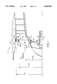
- FIG. 1 is a cross sectional side elevation of the fan section of a gas turbine engine showing a swept back fan blade according to the present invention.
- FIG. 2 is an enlarged view of the blade of FIG. 1 including an alternative leading edge profile shown by dotted lines and a prior art blade shown in phantom.
- FIG. 3 is a developed view taken along the line 3--3 of FIG. 2 illustrating the tips of four blades of the present invention along with four prior art blades shown in phantom.
- FIG. 4 is a schematic perspective view of an airfoil fragment illustrating the definition of sweep angle.
- FIG. 5 is a developed view similar to FIG. 3 illustrating an alternative embodiment of the invention and showing prior art blades in phantom.
- FIG. 6 is a cross sectional side elevation of the fan section of a gas turbine engine showing a forward swept fan blade according to the present invention and showing a prior art fan blade in phantom.
- FIG. 7 is a developed view taken along the line 7--7 of FIG. 6 illustrating the tips of four blades of the present invention along with four prior art blades shown in phantom.
- the forward end of a gas turbine engine includes a fan section 10 having a cascade of fan blades 12.
- Each blade has an attachment 14 for attaching the blade to a disk or hub 16 which is rotatable about a longitudinally extending rotational axis 18.
- Each blade also has a circumferentially extending platform 20 radially outward of the attachment.
- An airfoil 22 extending radially outward from each platform has a root 24, a tip 26, a leading edge 28, a trailing edge 30, a pressure surface 32 and a suction surface 34.
- the axially forwardmost extremity of the leading edge defines an inner transition point 40 at an inner transition radius r t -inner, radially inward of the tip.
- the blade cascade is circumscribed by a case 42 which forms the cascade's outer flowpath boundary.
- the case includes a rubstrip 46 which partially abrades away in the event that a rotating blade contacts the case during engine operation.
- a working medium fluid such as air 48 is pressurized as it flows axially through interblade passages 50 between neighboring airfoils.
- the hub 16 is attached to a shaft 52.
- a turbine (not shown) rotates the shaft, and therefore the hub and the blades, about the axis 18 in direction R.
- Each blade therefore, has a leading neighbor which precedes it and a trailing neighbor which follows it during rotation of the blades about the rotational axis.
- the axial velocity V x (FIG. 3) of the working medium is substantially constant across the radius of the flowpath.
- the linear velocity U of a rotating airfoil increases with increasing radius.
- the relative velocity V r of the working medium at the airfoil leading edge increases with increasing radius, and at high enough rotational speeds, the airfoil experiences supersonic working medium flow velocities in the vicinity of its tip.
- Supersonic flow over an airfoil while beneficial for maximizing the pressurization of the working medium, has the undesirable effect of reducing fan efficiency by introducing losses in the working medium's velocity and total pressure.
- the sweep angle ⁇ at any arbitrary radius is the acute angle between a line 54 tangent to the leading edge 28 of the airfoil 22 and a plane 56 perpendicular to the relative velocity vector V r .
- the sweep angle is measured in plane 58 which contains both the relative velocity vector and the tangent line and is perpendicular to plane 56.
- sweep angles ⁇ 1 and ⁇ 2 referred to hereinafter and illustrated in FIGS. 2, 3 and 6 are shown as projections of the actual sweep angle onto the plane of the illustrations.
- Sweeping the blade leading edge while useful for minimizing the adverse effects of supersonic working medium velocity, has the undesirable side effect of creating an endwall reflection shock.
- the flow of the working medium over the blade suction surface generates pressure waves 60 (shown only in FIG. 1) which extend along the span of the blade and reflect off the case.
- the reflected waves 62 and the incident waves 60 coalesce in the vicinity of the case to form an endwall shock 64 across each interblade passage.
- the endwall shock extends radially inward a limited distance, d, from the case.
- each endwall shock is also oblique to a plane 67 perpendicular to the rotational axis so that the shock extends axially and circumferentially.
- an endwall shock can extend across multiple interblade passages and affect the working medium entering those passages.
- expansion waves (as illustrated by the representative waves 68) propagate axially forward from each airfoil and weaken the endwall shock from the airfoil's leading neighbor so that each endwall shock usually affects only the passage where the endwall shock originated.
- the supersonic character of the flow causes passage shocks 66 to extend across the passages.
- the passage shocks which are unrelated to endwall reflections, extend from the leading edge of each blade to the suction surface of the blade's leading neighbor.
- the working medium is subjected to the aerodynamic losses of multiple shocks with a corresponding degradation of engine efficiency.
- the endwall shock can be eliminated by making the case wall perpendicular to the incident expansion waves so that the incident waves coincide with their reflections.
- design considerations such as constraints on the flowpath area and limitations on the case construction, may make this option unattractive or unavailable.
- coincidence of the endwall shock and the passage shock is achieved by uniquely shaping the airfoil so that the airfoil intercepts the endwall shock extending from the airfoil's leading neighbor and results in coincidence between the endwall shock and the passage shock.
- a swept back airfoil according to the present invention has a leading edge 28, a trailing edge 30, a root 24 and a tip 26 located at a tip radius r tip .
- An inner transition point 40 located at an inner transition radius r t -inner is the axially forwardmost point on the leading edge.
- the leading edge of the airfoil is swept back by a radially varying first sweep angle ⁇ 1 in an intermediate region 70 of the airfoil (in FIG. 2 plane 56 appears as the line defined by the plane's intersection with the plane of the illustration and in FIG. 3 the tangent line 54 appears as the point where the tangent line penetrates the plane of the Figure).
- the intermediate region 70 is the region radially bounded by the inner transition radius r t -inner and the outer transition radius r t -outer.
- the first sweep angle as is customary in the art, is nondecreasing with increasing radius, i.e. the sweep angle increases, or at least does not decrease, with increasing radius.
- the leading edge 28 of the airfoil is also swept back by a radially varying second sweep angle ⁇ 2 in a tip region 74 of the airfoil.
- the tip region is radially bounded by the outer transition radius r t -outer and a tip radius r tip .
- the second sweep angle is nonincreasing (decreases, or at least does not increase) with increasing radius. This is in sharp contrast to the prior art airfoil 22' whose sweep angle increases with increasing radius radially outward of the inner transition radius.
- FIG. 3 compares the invention (and the associated endwall and passage shocks) to a prior art blade (and its associated shocks) shown in phantom.
- the endwall shock 64 originates as a result of the pressure waves 60 (FIG. 1) extending along the suction surface of each blade.
- Each endwall shock is oblique to a plane 67 perpendicular to the rotational axis, and extends across the interblade passage of origin.
- the passage shock 66 also extends across the flow passage from the leading edge of a blade to the suction surface of the blade's leading neighbor. The working medium entering the passages is therefore adversely influenced by multiple shocks.
- the nonincreasing character of the second sweep angle of a swept back airfoil 22 causes a portion of the airfoil leading edge to be far enough forward (upstream) in the working medium flow that the section of the airfoil radially coextensive with the endwall shock extending from the airfoil's leading neighbor intercepts the endwall shock 64 (the unique sweep of the airfoil does not appreciably affect the location or orientation of the endwall shock; the phantom endwall shock associated with the prior art blade is illustrated slightly upstream of the endwall shock for the airfoil of the invention for illustrative clarity).
- the passage shock 66 (which remains attached to the airfoil leading edge and therefore is translated forward along with the leading edge) is brought into coincidence with the endwall shock so that the working medium does not encounter multiple shocks.
- FIGS. 2 and 3 illustrates a blade whose leading edge, in comparison to the leading edge of a conventional blade, has been translated axially forward parallel to the rotational axis (the corresponding translation of the trailing edge is an illustrative convenience--the location of the trailing edge is not embraced by the invention).
- the invention contemplates any blade whose airfoil intercepts the endwall shock to bring the passage shock into coincidence with the endwall shock.
- FIG. 5 illustrates an embodiment where a section of the tip region is displaced circumferentially (relative to the prior art blade) so that the blade intercepts the endwall shock 64 and brings it into coincidence with the passage shock 66.
- FIG. 5 illustrates an embodiment where a section of the tip region is displaced circumferentially (relative to the prior art blade) so that the blade intercepts the endwall shock 64 and brings it into coincidence with the passage shock 66.
- the displaced section extends radially inward far enough to intercept the endwall shock over its entire radial extent and brings it into coincidence with the passage shock 66.
- This embodiment functions as effectively as the embodiment of FIG. 3 in terms of bringing the passage shock into coincidence with the endwall shock.
- the airfoil tip is curled in the direction of rotation R. In the event that the blade tip contacts the rubstrip 46 during engine operation, the curled blade tip will gouge rather than abrade the rubstrip necessitating its replacement.
- Other alternative embodiments may also suffer from this or other disadvantages.
- a forward swept airfoil 122 according to the present invention has a leading edge 128, a trailing edge 130, a root 124 and a tip 126 located at a tip radius r tip .
- An inner transition point 140 located at an inner transition radius r t -inner is the axially aftmost point on the leading edge.
- the leading edge of the airfoil is swept forward by a radially varying first sweep angle ⁇ 1 in an intermediate region 70 of the airfoil.
- the intermediate region is radially bounded by the inner transition radius r t -inner and the outer transition radius r t -outer.
- the first sweep angle ⁇ 1 is nondecreasing with increasing radius, i.e. the sweep angle increases, or at least does not decrease, with increasing radius.
- the leading edge 128 of the airfoil is also swept forward by a radially varying second sweep angle ⁇ 2 in a tip region 74 of the airfoil.
- the tip region is radially bounded by the outer transition radius r t -outer and the tip radius r tip .
- the second sweep angle is nonincreasing (decreases, or at least does not increase) with increasing radius. This is in sharp contrast to the prior art airfoil 122' whose sweep angle increases with increasing radius radially outward of the inner transition radius.
- the nonincreasing sweep angle ⁇ 2 in the tip region 74 causes the endwall shock 64 to be coincident with the passage shock 66 for reducing the aerodynamic losses as discussed previously. This is in contrast to the prior art blade, shown in phantom where the endwall shock and the passage shock are distinct and therefore impose multiple aerodynamic losses on the working medium.
- the inner transition point is the axially forwardmost point on the leading edge.
- the leading edge is swept back at radii greater than the inner transition radius.
- the character of the leading edge sweep inward of the inner transition radius is not embraced by the invention.
- the inner transition point is the axially aftmost point on the leading edge.
- the leading edge is swept forward at radii greater than the inner transition radius.
- the character of the leading edge sweep inward of the inner transition radius is not embraced by the invention.
- the inner transition point is illustrated as being radially outward of the airfoil root.
- the invention also comprehends a blade whose inner transition point (axially forwardmost point for the swept back embodiment and axially aftmost point for the forward swept embodiment) is radially coincident with the leading edge of the root. This is shown, for example, by the dotted leading edge 28" of FIG. 2.
- the invention has been presented in the context of a fan blade for a gas turbine engine, however, the invention's applicability extends to any turbomachinery airfoil wherein flow passages between neighboring airfoils are subjected to multiple shocks.
Abstract
Description
Claims (3)
Priority Applications (13)
| Application Number | Priority Date | Filing Date | Title |
|---|---|---|---|
| US08/559,965 US5642985A (en) | 1995-11-17 | 1995-11-17 | Swept turbomachinery blade |
| JP30141696A JP3902278B2 (en) | 1995-11-17 | 1996-11-13 | Turbomachine blade |
| DE69634933T DE69634933T2 (en) | 1995-11-17 | 1996-11-15 | Chiseled turbo machine shovel |
| EP96308303A EP0774567B1 (en) | 1995-11-17 | 1996-11-15 | Swept turbomachinery blade |
| EP10012698A EP2278124A1 (en) | 1995-11-17 | 1996-11-15 | Swept turbomachinery blade |
| EP05008514A EP1571342B1 (en) | 1995-11-17 | 1996-11-15 | Swept turbomachinery blade |
| EP01112128A EP1138877B1 (en) | 1995-11-17 | 1996-11-15 | Swept turbomachinery blade |
| DE1138877T DE1138877T1 (en) | 1995-11-17 | 1996-11-15 | Swept turbomachine bucket |
| DE69622002T DE69622002T2 (en) | 1995-11-17 | 1996-11-15 | Swept turbo machine blade |
| US09/343,736 USRE38040E1 (en) | 1995-11-17 | 1999-06-30 | Swept turbomachinery blade |
| US09/874,931 USRE43710E1 (en) | 1995-11-17 | 2001-06-05 | Swept turbomachinery blade |
| JP2006302189A JP4417947B2 (en) | 1995-11-17 | 2006-11-08 | Turbomachine blade |
| US12/785,222 USRE45689E1 (en) | 1995-11-17 | 2010-05-21 | Swept turbomachinery blade |
Applications Claiming Priority (1)
| Application Number | Priority Date | Filing Date | Title |
|---|---|---|---|
| US08/559,965 US5642985A (en) | 1995-11-17 | 1995-11-17 | Swept turbomachinery blade |
Related Parent Applications (2)
| Application Number | Title | Priority Date | Filing Date |
|---|---|---|---|
| US09/343,736 Continuation USRE38040E1 (en) | 1995-11-17 | 1999-06-30 | Swept turbomachinery blade |
| US09/874,931 Continuation USRE43710E1 (en) | 1995-11-17 | 2001-06-05 | Swept turbomachinery blade |
Related Child Applications (3)
| Application Number | Title | Priority Date | Filing Date |
|---|---|---|---|
| US09/343,736 Reissue USRE38040E1 (en) | 1995-11-17 | 1999-06-30 | Swept turbomachinery blade |
| US09/874,931 Reissue USRE43710E1 (en) | 1995-11-17 | 2001-06-05 | Swept turbomachinery blade |
| US12/785,222 Reissue USRE45689E1 (en) | 1995-11-17 | 2010-05-21 | Swept turbomachinery blade |
Publications (1)
| Publication Number | Publication Date |
|---|---|
| US5642985A true US5642985A (en) | 1997-07-01 |
Family
ID=24235807
Family Applications (4)
| Application Number | Title | Priority Date | Filing Date |
|---|---|---|---|
| US08/559,965 Ceased US5642985A (en) | 1995-11-17 | 1995-11-17 | Swept turbomachinery blade |
| US09/343,736 Expired - Lifetime USRE38040E1 (en) | 1995-11-17 | 1999-06-30 | Swept turbomachinery blade |
| US09/874,931 Expired - Lifetime USRE43710E1 (en) | 1995-11-17 | 2001-06-05 | Swept turbomachinery blade |
| US12/785,222 Expired - Lifetime USRE45689E1 (en) | 1995-11-17 | 2010-05-21 | Swept turbomachinery blade |
Family Applications After (3)
| Application Number | Title | Priority Date | Filing Date |
|---|---|---|---|
| US09/343,736 Expired - Lifetime USRE38040E1 (en) | 1995-11-17 | 1999-06-30 | Swept turbomachinery blade |
| US09/874,931 Expired - Lifetime USRE43710E1 (en) | 1995-11-17 | 2001-06-05 | Swept turbomachinery blade |
| US12/785,222 Expired - Lifetime USRE45689E1 (en) | 1995-11-17 | 2010-05-21 | Swept turbomachinery blade |
Country Status (4)
| Country | Link |
|---|---|
| US (4) | US5642985A (en) |
| EP (4) | EP1571342B1 (en) |
| JP (2) | JP3902278B2 (en) |
| DE (3) | DE1138877T1 (en) |
Cited By (67)
| Publication number | Priority date | Publication date | Assignee | Title |
|---|---|---|---|---|
| US6071077A (en) * | 1996-04-09 | 2000-06-06 | Rolls-Royce Plc | Swept fan blade |
| US6195983B1 (en) | 1999-02-12 | 2001-03-06 | General Electric Company | Leaned and swept fan outlet guide vanes |
| US6299412B1 (en) | 1999-12-06 | 2001-10-09 | General Electric Company | Bowed compressor airfoil |
| US6312219B1 (en) | 1999-11-05 | 2001-11-06 | General Electric Company | Narrow waist vane |
| US6328533B1 (en) | 1999-12-21 | 2001-12-11 | General Electric Company | Swept barrel airfoil |
| US6338609B1 (en) | 2000-02-18 | 2002-01-15 | General Electric Company | Convex compressor casing |
| US6371721B1 (en) * | 1999-09-25 | 2002-04-16 | Rolls-Royce Plc | Gas turbine engine blade containment assembly |
| US6561761B1 (en) | 2000-02-18 | 2003-05-13 | General Electric Company | Fluted compressor flowpath |
| US20050031454A1 (en) * | 2003-08-05 | 2005-02-10 | Doloresco Bryan Keith | Counterstagger compressor airfoil |
| US20050249578A1 (en) * | 2004-05-07 | 2005-11-10 | Leblanc Andre D | Shockwave-induced boundary layer bleed |
| US20050254956A1 (en) * | 2004-05-14 | 2005-11-17 | Pratt & Whitney Canada Corp. | Fan blade curvature distribution for high core pressure ratio fan |
| US20060067821A1 (en) * | 2004-09-28 | 2006-03-30 | Wadia Aspi R | Methods and apparatus for aerodynamically self-enhancing rotor blades |
| US20060165520A1 (en) * | 2004-11-12 | 2006-07-27 | Volker Guemmer | Blade of a turbomachine with enlarged peripheral profile depth |
| US20060228206A1 (en) * | 2005-04-07 | 2006-10-12 | General Electric Company | Low solidity turbofan |
| DE102005059438B3 (en) * | 2005-12-13 | 2007-07-19 | Deutsches Zentrum für Luft- und Raumfahrt e.V. | Turbo-jet engine e.g. bypass engine, for e.g. commercial aircraft, has rotors arrowed in opposite directions in such a manner that rotor distance is increased with increasing radius, and rotor blades bent against each other in convex manner |
| US20070243068A1 (en) * | 2005-04-07 | 2007-10-18 | General Electric Company | Tip cambered swept blade |
| EP1905952A2 (en) | 2006-09-12 | 2008-04-02 | United Technologies Corporation | Turbine engine compressor vane and spacer |
| US20080131272A1 (en) * | 2006-11-30 | 2008-06-05 | General Electric Company | Advanced booster system |
| US20080286107A1 (en) * | 2007-04-27 | 2008-11-20 | Carsten Clemen | Course of leading edges for turbomachine components |
| US20090191049A1 (en) * | 2008-01-30 | 2009-07-30 | Snecma | Turbojet compressor |
| US20100054946A1 (en) * | 2008-09-04 | 2010-03-04 | John Orosa | Compressor blade with forward sweep and dihedral |
| US20100068064A1 (en) * | 2006-11-02 | 2010-03-18 | Mitsubishi Heavy Industries, Ltd. | Transonic airfoil and axial flow rotary machine |
| US20100215503A1 (en) * | 2009-02-25 | 2010-08-26 | Hitachi, Ltd | Transonic blade |
| US20100260609A1 (en) * | 2006-11-30 | 2010-10-14 | General Electric Company | Advanced booster rotor blade |
| US20130008170A1 (en) * | 2011-07-05 | 2013-01-10 | Gallagher Edward J | Subsonic swept fan blade |
| US20130224040A1 (en) * | 2012-02-29 | 2013-08-29 | Joseph C. Straccia | High order shaped curve region for an airfoil |
| US20130315726A1 (en) * | 2012-05-24 | 2013-11-28 | General Electric Company | Turbine and method for reducing shock losses in a turbine |
| US20140133982A1 (en) * | 2011-04-15 | 2014-05-15 | Centre De Recherche En Aeronautique Asbl-Cenaero | Propulsion device having unducted counter-rotating and coaxial rotors |
| CN103958833A (en) * | 2011-11-29 | 2014-07-30 | 斯奈克玛 | Turbine engine vane, in particular for a one-piece bladed disk |
| WO2015023325A1 (en) * | 2013-08-12 | 2015-02-19 | United Technologies Corporation | Non-axisymmetric fan flow path |
| US20150152880A1 (en) * | 2012-05-31 | 2015-06-04 | Snecma | Airplane turbojet fan blade of cambered profile in its root sections |
| US9140127B2 (en) | 2014-02-19 | 2015-09-22 | United Technologies Corporation | Gas turbine engine airfoil |
| US9163517B2 (en) * | 2014-02-19 | 2015-10-20 | United Technologies Corporation | Gas turbine engine airfoil |
| US9347323B2 (en) | 2014-02-19 | 2016-05-24 | United Technologies Corporation | Gas turbine engine airfoil total chord relative to span |
| US9353628B2 (en) | 2014-02-19 | 2016-05-31 | United Technologies Corporation | Gas turbine engine airfoil |
| US20160341213A1 (en) * | 2014-02-19 | 2016-11-24 | United Technologies Corporation | Gas turbine engine airfoil |
| RU2606294C1 (en) * | 2015-07-06 | 2017-01-10 | Федеральное государственное унитарное предприятие "Центральный институт авиационного моторостроения имени П.И. Баранова" | High-speed axial fan impeller |
| US20170022820A1 (en) * | 2015-07-20 | 2017-01-26 | Rolls-Royce Plc | Aerofoil |
| US9568009B2 (en) | 2013-03-11 | 2017-02-14 | Rolls-Royce Corporation | Gas turbine engine flow path geometry |
| US9567858B2 (en) | 2014-02-19 | 2017-02-14 | United Technologies Corporation | Gas turbine engine airfoil |
| US9574567B2 (en) | 2013-10-01 | 2017-02-21 | General Electric Company | Supersonic compressor and associated method |
| US9599064B2 (en) | 2014-02-19 | 2017-03-21 | United Technologies Corporation | Gas turbine engine airfoil |
| US9695695B2 (en) | 2012-01-30 | 2017-07-04 | Snecma | Turbojet fan blade |
| RU2629110C2 (en) * | 2011-09-09 | 2017-08-24 | Сименс Акциенгезелльшафт | Method of profiling a replacement shoot as a replacement parts for old pulley for a turbomachine with a two-direction of the flow |
| RU2635734C2 (en) * | 2012-04-04 | 2017-11-15 | Снекма | Turbomachine rotor blade |
| US9920653B2 (en) | 2012-12-20 | 2018-03-20 | United Technologies Corporation | Low pressure ratio fan engine having a dimensional relationship between inlet and fan size |
| US9932933B2 (en) * | 2012-12-20 | 2018-04-03 | United Technologies Corporation | Low pressure ratio fan engine having a dimensional relationship between inlet and fan size |
| US10036257B2 (en) | 2014-02-19 | 2018-07-31 | United Technologies Corporation | Gas turbine engine airfoil |
| US20180231020A1 (en) * | 2017-02-14 | 2018-08-16 | Rolls-Royce Plc | Gas turbine engine fan blade with axial lean |
| US20190162070A1 (en) * | 2017-11-24 | 2019-05-30 | Rolls-Royce Plc | Gas turbine engine |
| US10309414B2 (en) | 2014-02-19 | 2019-06-04 | United Technologies Corporation | Gas turbine engine airfoil |
| US10352331B2 (en) | 2014-02-19 | 2019-07-16 | United Technologies Corporation | Gas turbine engine airfoil |
| US10385866B2 (en) | 2014-02-19 | 2019-08-20 | United Technologies Corporation | Gas turbine engine airfoil |
| US10393139B2 (en) | 2014-02-19 | 2019-08-27 | United Technologies Corporation | Gas turbine engine airfoil |
| US10422226B2 (en) | 2014-02-19 | 2019-09-24 | United Technologies Corporation | Gas turbine engine airfoil |
| US10450879B2 (en) * | 2015-11-23 | 2019-10-22 | Rolls-Royce Plc | Gas turbine engine |
| US10458426B2 (en) | 2016-09-15 | 2019-10-29 | General Electric Company | Aircraft fan with low part-span solidity |
| US10479519B2 (en) * | 2015-12-31 | 2019-11-19 | United Technologies Corporation | Nacelle short inlet for fan blade removal |
| US10495106B2 (en) | 2014-02-19 | 2019-12-03 | United Technologies Corporation | Gas turbine engine airfoil |
| US10502229B2 (en) | 2014-02-19 | 2019-12-10 | United Technologies Corporation | Gas turbine engine airfoil |
| US10519971B2 (en) | 2014-02-19 | 2019-12-31 | United Technologies Corporation | Gas turbine engine airfoil |
| US10557477B2 (en) | 2014-02-19 | 2020-02-11 | United Technologies Corporation | Gas turbine engine airfoil |
| US10570915B2 (en) | 2014-02-19 | 2020-02-25 | United Technologies Corporation | Gas turbine engine airfoil |
| US10570916B2 (en) | 2014-02-19 | 2020-02-25 | United Technologies Corporation | Gas turbine engine airfoil |
| US10584715B2 (en) | 2014-02-19 | 2020-03-10 | United Technologies Corporation | Gas turbine engine airfoil |
| US10590775B2 (en) | 2014-02-19 | 2020-03-17 | United Technologies Corporation | Gas turbine engine airfoil |
| US10605259B2 (en) | 2014-02-19 | 2020-03-31 | United Technologies Corporation | Gas turbine engine airfoil |
Families Citing this family (19)
| Publication number | Priority date | Publication date | Assignee | Title |
|---|---|---|---|---|
| US5642985A (en) * | 1995-11-17 | 1997-07-01 | United Technologies Corporation | Swept turbomachinery blade |
| GB9607316D0 (en) * | 1996-04-09 | 1996-06-12 | Rolls Royce Plc | Swept fan blade |
| DE19812624A1 (en) * | 1998-03-23 | 1999-09-30 | Bmw Rolls Royce Gmbh | Rotor blade of an axial flow machine |
| EP0957236A1 (en) * | 1998-05-15 | 1999-11-17 | Asea Brown Boveri AG | Turbine rotor blade |
| US20030210980A1 (en) * | 2002-01-29 | 2003-11-13 | Ramgen Power Systems, Inc. | Supersonic compressor |
| US7334990B2 (en) * | 2002-01-29 | 2008-02-26 | Ramgen Power Systems, Inc. | Supersonic compressor |
| US7293955B2 (en) * | 2002-09-26 | 2007-11-13 | Ramgen Power Systrms, Inc. | Supersonic gas compressor |
| US7434400B2 (en) * | 2002-09-26 | 2008-10-14 | Lawlor Shawn P | Gas turbine power plant with supersonic shock compression ramps |
| FR2851798B1 (en) * | 2003-02-27 | 2005-04-29 | Snecma Moteurs | TURBOREACTOR TURBINE BOW |
| DE102004011607B4 (en) * | 2004-03-10 | 2016-11-24 | MTU Aero Engines AG | Compressor of a gas turbine and gas turbine |
| JP4863162B2 (en) | 2006-05-26 | 2012-01-25 | 株式会社Ihi | Fan blade of turbofan engine |
| GB0620769D0 (en) | 2006-10-19 | 2006-11-29 | Rolls Royce Plc | A fan blade |
| FR2908152B1 (en) * | 2006-11-08 | 2009-02-06 | Snecma Sa | TURBOMACHINE TURBINE BOW |
| US8087884B2 (en) | 2006-11-30 | 2012-01-03 | General Electric Company | Advanced booster stator vane |
| DE102007028788B4 (en) * | 2007-06-22 | 2013-04-18 | Thermo King Container-Denmark A/S | Refrigerated container for ships |
| WO2009000461A2 (en) * | 2007-06-22 | 2008-12-31 | Thermo King Deutschland Gmbh | Refrigerating container for land, road and rail vehicles |
| DE102007028787B4 (en) * | 2007-06-22 | 2013-05-23 | Ingersoll-Rand Klimasysteme Deutschland Gmbh | Refrigerated container for land, road and rail vehicles |
| JP2009008014A (en) * | 2007-06-28 | 2009-01-15 | Mitsubishi Electric Corp | Axial flow fan |
| FR3129686A1 (en) * | 2021-11-29 | 2023-06-02 | Safran Aircraft Engines | Blade for a ducted fan of a turbomachine |
Citations (18)
| Publication number | Priority date | Publication date | Assignee | Title |
|---|---|---|---|---|
| US1964525A (en) * | 1932-07-30 | 1934-06-26 | Gen Electric | Fan blade |
| US2154313A (en) * | 1938-04-01 | 1939-04-11 | Gen Electric | Directing vane |
| US2915238A (en) * | 1953-10-23 | 1959-12-01 | Szydlowski Joseph | Axial flow compressors |
| US2934259A (en) * | 1956-06-18 | 1960-04-26 | United Aircraft Corp | Compressor blading |
| US2935246A (en) * | 1949-06-02 | 1960-05-03 | Onera (Off Nat Aerospatiale) | Shock wave compressors, especially for use in connection with continuous flow engines for aircraft |
| US3416725A (en) * | 1967-10-12 | 1968-12-17 | Acme Engineering And Mfg Corp | Dihedral bladed ventilating fan |
| US3444817A (en) * | 1967-08-23 | 1969-05-20 | William J Caldwell | Fluid pump |
| US3692425A (en) * | 1969-01-02 | 1972-09-19 | Gen Electric | Compressor for handling gases at velocities exceeding a sonic value |
| US3989406A (en) * | 1974-11-26 | 1976-11-02 | Bolt Beranek And Newman, Inc. | Method of and apparatus for preventing leading edge shocks and shock-related noise in transonic and supersonic rotor blades and the like |
| US4012172A (en) * | 1975-09-10 | 1977-03-15 | Avco Corporation | Low noise blades for axial flow compressors |
| US4358246A (en) * | 1979-07-16 | 1982-11-09 | United Technologies Corporation | Noise reduction means for prop-fan and the construction thereof |
| US4408957A (en) * | 1972-02-22 | 1983-10-11 | General Motors Corporation | Supersonic blading |
| US4726737A (en) * | 1986-10-28 | 1988-02-23 | United Technologies Corporation | Reduced loss swept supersonic fan blade |
| US4737077A (en) * | 1986-09-12 | 1988-04-12 | Aciers Et Outillage Peugeot | Profiled blade of a fan and its application in motor-driven ventilating devices |
| US4784575A (en) * | 1986-11-19 | 1988-11-15 | General Electric Company | Counterrotating aircraft propulsor blades |
| SU1528965A1 (en) * | 1988-02-17 | 1989-12-15 | Ташкентский Политехнический Институт Им.А.Р.Бируни | Impeller of centrifugal fan |
| US5112192A (en) * | 1990-07-26 | 1992-05-12 | General Signal Corporation | Mixing impellers and impeller systems for mixing and blending liquids and liquid suspensions having a wide range of viscosities |
| US5167489A (en) * | 1991-04-15 | 1992-12-01 | General Electric Company | Forward swept rotor blade |
Family Cites Families (27)
| Publication number | Priority date | Publication date | Assignee | Title |
|---|---|---|---|---|
| US2735612A (en) * | 1956-02-21 | hausmann | ||
| US2628768A (en) | 1946-03-27 | 1953-02-17 | Kantrowitz Arthur | Axial-flow compressor |
| FR996967A (en) * | 1949-09-06 | 1951-12-31 | Rateau Soc | Improvement in turbine engine blades |
| US2689681A (en) | 1949-09-17 | 1954-09-21 | United Aircraft Corp | Reversely rotating screw type multiple impeller compressor |
| US2660401A (en) * | 1951-08-07 | 1953-11-24 | Gen Electric | Turbine bucket |
| US2830753A (en) * | 1951-11-10 | 1958-04-15 | Edward A Stalker | Axial flow compressors with circular arc blades |
| US3546882A (en) * | 1968-04-24 | 1970-12-15 | Gen Electric | Gas turbine engines |
| US3843277A (en) * | 1973-02-14 | 1974-10-22 | Gen Electric | Sound attenuating inlet duct |
| US4012165A (en) | 1975-12-08 | 1977-03-15 | United Technologies Corporation | Fan structure |
| US4123196A (en) * | 1976-11-01 | 1978-10-31 | General Electric Company | Supersonic compressor with off-design performance improvement |
| GB1598616A (en) | 1977-06-29 | 1981-09-23 | Kawasaki Heavy Ind Ltd | Diagonal-flow fan wheel with blades of developable surface shape |
| IT1165216B (en) * | 1979-06-15 | 1987-04-22 | Mancinelli Euro Emme | FAN GROUP FOR AIR CONVEYMENT THROUGH A CIRCULAR OPENING |
| US4370097A (en) | 1979-07-16 | 1983-01-25 | United Technologies Corporation | Noise reduction means for prop-fan |
| GB2164098B (en) * | 1984-09-07 | 1988-12-07 | Rolls Royce | Improvements in or relating to aerofoil section members for turbine engines |
| JPS62114105U (en) * | 1986-01-09 | 1987-07-20 | ||
| JPS63126501U (en) * | 1987-02-13 | 1988-08-18 | ||
| JPH0745801B2 (en) * | 1988-08-11 | 1995-05-17 | 三菱重工業株式会社 | Three-dimensional turbine rotor blade |
| US5064345A (en) | 1989-11-16 | 1991-11-12 | Airflow Research And Manufacturing Corporation | Multi-sweep blade with abrupt sweep transition |
| US5088892A (en) * | 1990-02-07 | 1992-02-18 | United Technologies Corporation | Bowed airfoil for the compression section of a rotary machine |
| JPH0527201U (en) * | 1991-09-19 | 1993-04-09 | 株式会社日立製作所 | Axial turbine |
| GB9307288D0 (en) | 1993-04-07 | 1993-06-02 | Rolls Royce Plc | Gas turbine engine casing construction |
| JPH07224794A (en) * | 1993-12-14 | 1995-08-22 | Mitsubishi Heavy Ind Ltd | Moving blade of axial flow machine |
| JP3118136B2 (en) * | 1994-03-28 | 2000-12-18 | 株式会社先進材料利用ガスジェネレータ研究所 | Axial compressor casing |
| US5584661A (en) | 1994-05-02 | 1996-12-17 | The United States Of America As Represented By The Administrator Of The National Aeronautics And Space Administration | Forward sweep, low noise rotor blade |
| US5642985A (en) | 1995-11-17 | 1997-07-01 | United Technologies Corporation | Swept turbomachinery blade |
| US6071077A (en) | 1996-04-09 | 2000-06-06 | Rolls-Royce Plc | Swept fan blade |
| GB9607316D0 (en) | 1996-04-09 | 1996-06-12 | Rolls Royce Plc | Swept fan blade |
-
1995
- 1995-11-17 US US08/559,965 patent/US5642985A/en not_active Ceased
-
1996
- 1996-11-13 JP JP30141696A patent/JP3902278B2/en not_active Expired - Lifetime
- 1996-11-15 EP EP05008514A patent/EP1571342B1/en not_active Expired - Lifetime
- 1996-11-15 EP EP96308303A patent/EP0774567B1/en not_active Expired - Lifetime
- 1996-11-15 DE DE1138877T patent/DE1138877T1/en active Pending
- 1996-11-15 EP EP01112128A patent/EP1138877B1/en not_active Expired - Lifetime
- 1996-11-15 EP EP10012698A patent/EP2278124A1/en not_active Withdrawn
- 1996-11-15 DE DE69622002T patent/DE69622002T2/en not_active Expired - Lifetime
- 1996-11-15 DE DE69634933T patent/DE69634933T2/en not_active Expired - Lifetime
-
1999
- 1999-06-30 US US09/343,736 patent/USRE38040E1/en not_active Expired - Lifetime
-
2001
- 2001-06-05 US US09/874,931 patent/USRE43710E1/en not_active Expired - Lifetime
-
2006
- 2006-11-08 JP JP2006302189A patent/JP4417947B2/en not_active Expired - Lifetime
-
2010
- 2010-05-21 US US12/785,222 patent/USRE45689E1/en not_active Expired - Lifetime
Patent Citations (18)
| Publication number | Priority date | Publication date | Assignee | Title |
|---|---|---|---|---|
| US1964525A (en) * | 1932-07-30 | 1934-06-26 | Gen Electric | Fan blade |
| US2154313A (en) * | 1938-04-01 | 1939-04-11 | Gen Electric | Directing vane |
| US2935246A (en) * | 1949-06-02 | 1960-05-03 | Onera (Off Nat Aerospatiale) | Shock wave compressors, especially for use in connection with continuous flow engines for aircraft |
| US2915238A (en) * | 1953-10-23 | 1959-12-01 | Szydlowski Joseph | Axial flow compressors |
| US2934259A (en) * | 1956-06-18 | 1960-04-26 | United Aircraft Corp | Compressor blading |
| US3444817A (en) * | 1967-08-23 | 1969-05-20 | William J Caldwell | Fluid pump |
| US3416725A (en) * | 1967-10-12 | 1968-12-17 | Acme Engineering And Mfg Corp | Dihedral bladed ventilating fan |
| US3692425A (en) * | 1969-01-02 | 1972-09-19 | Gen Electric | Compressor for handling gases at velocities exceeding a sonic value |
| US4408957A (en) * | 1972-02-22 | 1983-10-11 | General Motors Corporation | Supersonic blading |
| US3989406A (en) * | 1974-11-26 | 1976-11-02 | Bolt Beranek And Newman, Inc. | Method of and apparatus for preventing leading edge shocks and shock-related noise in transonic and supersonic rotor blades and the like |
| US4012172A (en) * | 1975-09-10 | 1977-03-15 | Avco Corporation | Low noise blades for axial flow compressors |
| US4358246A (en) * | 1979-07-16 | 1982-11-09 | United Technologies Corporation | Noise reduction means for prop-fan and the construction thereof |
| US4737077A (en) * | 1986-09-12 | 1988-04-12 | Aciers Et Outillage Peugeot | Profiled blade of a fan and its application in motor-driven ventilating devices |
| US4726737A (en) * | 1986-10-28 | 1988-02-23 | United Technologies Corporation | Reduced loss swept supersonic fan blade |
| US4784575A (en) * | 1986-11-19 | 1988-11-15 | General Electric Company | Counterrotating aircraft propulsor blades |
| SU1528965A1 (en) * | 1988-02-17 | 1989-12-15 | Ташкентский Политехнический Институт Им.А.Р.Бируни | Impeller of centrifugal fan |
| US5112192A (en) * | 1990-07-26 | 1992-05-12 | General Signal Corporation | Mixing impellers and impeller systems for mixing and blending liquids and liquid suspensions having a wide range of viscosities |
| US5167489A (en) * | 1991-04-15 | 1992-12-01 | General Electric Company | Forward swept rotor blade |
Cited By (124)
| Publication number | Priority date | Publication date | Assignee | Title |
|---|---|---|---|---|
| US6071077A (en) * | 1996-04-09 | 2000-06-06 | Rolls-Royce Plc | Swept fan blade |
| US6195983B1 (en) | 1999-02-12 | 2001-03-06 | General Electric Company | Leaned and swept fan outlet guide vanes |
| US6371721B1 (en) * | 1999-09-25 | 2002-04-16 | Rolls-Royce Plc | Gas turbine engine blade containment assembly |
| US6312219B1 (en) | 1999-11-05 | 2001-11-06 | General Electric Company | Narrow waist vane |
| US6299412B1 (en) | 1999-12-06 | 2001-10-09 | General Electric Company | Bowed compressor airfoil |
| US6328533B1 (en) | 1999-12-21 | 2001-12-11 | General Electric Company | Swept barrel airfoil |
| US6338609B1 (en) | 2000-02-18 | 2002-01-15 | General Electric Company | Convex compressor casing |
| US6561761B1 (en) | 2000-02-18 | 2003-05-13 | General Electric Company | Fluted compressor flowpath |
| US20050031454A1 (en) * | 2003-08-05 | 2005-02-10 | Doloresco Bryan Keith | Counterstagger compressor airfoil |
| US6899526B2 (en) * | 2003-08-05 | 2005-05-31 | General Electric Company | Counterstagger compressor airfoil |
| US7147426B2 (en) * | 2004-05-07 | 2006-12-12 | Pratt & Whitney Canada Corp. | Shockwave-induced boundary layer bleed |
| US20050249578A1 (en) * | 2004-05-07 | 2005-11-10 | Leblanc Andre D | Shockwave-induced boundary layer bleed |
| US7204676B2 (en) | 2004-05-14 | 2007-04-17 | Pratt & Whitney Canada Corp. | Fan blade curvature distribution for high core pressure ratio fan |
| US20050254956A1 (en) * | 2004-05-14 | 2005-11-17 | Pratt & Whitney Canada Corp. | Fan blade curvature distribution for high core pressure ratio fan |
| US20060067821A1 (en) * | 2004-09-28 | 2006-03-30 | Wadia Aspi R | Methods and apparatus for aerodynamically self-enhancing rotor blades |
| US7320575B2 (en) | 2004-09-28 | 2008-01-22 | General Electric Company | Methods and apparatus for aerodynamically self-enhancing rotor blades |
| US8382438B2 (en) * | 2004-11-12 | 2013-02-26 | Rolls-Royce Deutschland Ltd & Co Kg | Blade of a turbomachine with enlarged peripheral profile depth |
| US20060165520A1 (en) * | 2004-11-12 | 2006-07-27 | Volker Guemmer | Blade of a turbomachine with enlarged peripheral profile depth |
| US7476086B2 (en) | 2005-04-07 | 2009-01-13 | General Electric Company | Tip cambered swept blade |
| US20060228206A1 (en) * | 2005-04-07 | 2006-10-12 | General Electric Company | Low solidity turbofan |
| US20070243068A1 (en) * | 2005-04-07 | 2007-10-18 | General Electric Company | Tip cambered swept blade |
| US7374403B2 (en) | 2005-04-07 | 2008-05-20 | General Electric Company | Low solidity turbofan |
| DE102005059438B3 (en) * | 2005-12-13 | 2007-07-19 | Deutsches Zentrum für Luft- und Raumfahrt e.V. | Turbo-jet engine e.g. bypass engine, for e.g. commercial aircraft, has rotors arrowed in opposite directions in such a manner that rotor distance is increased with increasing radius, and rotor blades bent against each other in convex manner |
| US7726937B2 (en) | 2006-09-12 | 2010-06-01 | United Technologies Corporation | Turbine engine compressor vanes |
| EP1905952A2 (en) | 2006-09-12 | 2008-04-02 | United Technologies Corporation | Turbine engine compressor vane and spacer |
| US20100068064A1 (en) * | 2006-11-02 | 2010-03-18 | Mitsubishi Heavy Industries, Ltd. | Transonic airfoil and axial flow rotary machine |
| US8133012B2 (en) | 2006-11-02 | 2012-03-13 | Mitsubishi Heavy Industries, Ltd. | Transonic airfoil and axial flow rotary machine |
| US20080131272A1 (en) * | 2006-11-30 | 2008-06-05 | General Electric Company | Advanced booster system |
| US8517677B2 (en) | 2006-11-30 | 2013-08-27 | General Electric Company | Advanced booster system |
| US8292574B2 (en) * | 2006-11-30 | 2012-10-23 | General Electric Company | Advanced booster system |
| US20100260609A1 (en) * | 2006-11-30 | 2010-10-14 | General Electric Company | Advanced booster rotor blade |
| US7967571B2 (en) | 2006-11-30 | 2011-06-28 | General Electric Company | Advanced booster rotor blade |
| US20080286107A1 (en) * | 2007-04-27 | 2008-11-20 | Carsten Clemen | Course of leading edges for turbomachine components |
| US8047802B2 (en) | 2007-04-27 | 2011-11-01 | Rolls-Royce Deutschland Ltd & Co Kg | Course of leading edges for turbomachine components |
| US8152456B2 (en) * | 2008-01-30 | 2012-04-10 | Snecma | Turbojet compressor |
| US20090191049A1 (en) * | 2008-01-30 | 2009-07-30 | Snecma | Turbojet compressor |
| US20100054946A1 (en) * | 2008-09-04 | 2010-03-04 | John Orosa | Compressor blade with forward sweep and dihedral |
| US8147207B2 (en) | 2008-09-04 | 2012-04-03 | Siemens Energy, Inc. | Compressor blade having a ratio of leading edge sweep to leading edge dihedral in a range of 1:1 to 3:1 along the radially outer portion |
| US20100215503A1 (en) * | 2009-02-25 | 2010-08-26 | Hitachi, Ltd | Transonic blade |
| US8425185B2 (en) * | 2009-02-25 | 2013-04-23 | Hitachi, Ltd. | Transonic blade |
| US20140133982A1 (en) * | 2011-04-15 | 2014-05-15 | Centre De Recherche En Aeronautique Asbl-Cenaero | Propulsion device having unducted counter-rotating and coaxial rotors |
| US9593582B2 (en) * | 2011-04-15 | 2017-03-14 | Snecma | Propulsion device having unducted counter-rotating and coaxial rotors |
| US9790797B2 (en) * | 2011-07-05 | 2017-10-17 | United Technologies Corporation | Subsonic swept fan blade |
| US20130008170A1 (en) * | 2011-07-05 | 2013-01-10 | Gallagher Edward J | Subsonic swept fan blade |
| US9771803B2 (en) | 2011-09-09 | 2017-09-26 | Siemens Aktiengesellschaft | Method for profiling a replacement blade as a replacement part for an old blade for an axial-flow turbomachine |
| RU2629110C2 (en) * | 2011-09-09 | 2017-08-24 | Сименс Акциенгезелльшафт | Method of profiling a replacement shoot as a replacement parts for old pulley for a turbomachine with a two-direction of the flow |
| CN103958833B (en) * | 2011-11-29 | 2016-03-02 | 斯奈克玛 | A kind of turbine engine blade being used in particular for integral blade dish |
| CN103958833A (en) * | 2011-11-29 | 2014-07-30 | 斯奈克玛 | Turbine engine vane, in particular for a one-piece bladed disk |
| US9695695B2 (en) | 2012-01-30 | 2017-07-04 | Snecma | Turbojet fan blade |
| US20130224040A1 (en) * | 2012-02-29 | 2013-08-29 | Joseph C. Straccia | High order shaped curve region for an airfoil |
| US9726021B2 (en) | 2012-02-29 | 2017-08-08 | United Technologies Corporation | High order shaped curve region for an airfoil |
| US9017036B2 (en) * | 2012-02-29 | 2015-04-28 | United Technologies Corporation | High order shaped curve region for an airfoil |
| RU2635734C2 (en) * | 2012-04-04 | 2017-11-15 | Снекма | Turbomachine rotor blade |
| US20130315726A1 (en) * | 2012-05-24 | 2013-11-28 | General Electric Company | Turbine and method for reducing shock losses in a turbine |
| US9121285B2 (en) * | 2012-05-24 | 2015-09-01 | General Electric Company | Turbine and method for reducing shock losses in a turbine |
| US11333164B2 (en) * | 2012-05-31 | 2022-05-17 | Safran Aircraft Engines | Airplane turbojet fan blade of cambered profile in its root sections |
| US20150152880A1 (en) * | 2012-05-31 | 2015-06-04 | Snecma | Airplane turbojet fan blade of cambered profile in its root sections |
| US10301971B2 (en) | 2012-12-20 | 2019-05-28 | United Technologies Corporation | Low pressure ratio fan engine having a dimensional relationship between inlet and fan size |
| US9920653B2 (en) | 2012-12-20 | 2018-03-20 | United Technologies Corporation | Low pressure ratio fan engine having a dimensional relationship between inlet and fan size |
| US9932933B2 (en) * | 2012-12-20 | 2018-04-03 | United Technologies Corporation | Low pressure ratio fan engine having a dimensional relationship between inlet and fan size |
| US11781447B2 (en) | 2012-12-20 | 2023-10-10 | Rtx Corporation | Low pressure ratio fan engine having a dimensional relationship between inlet and fan size |
| US11781505B2 (en) | 2012-12-20 | 2023-10-10 | Rtx Corporation | Low pressure ratio fan engine having a dimensional relationship between inlet and fan size |
| US11286811B2 (en) | 2012-12-20 | 2022-03-29 | Raytheon Technologies Corporation | Low pressure ratio fan engine having a dimensional relationship between inlet and fan size |
| US11015550B2 (en) | 2012-12-20 | 2021-05-25 | Raytheon Technologies Corporation | Low pressure ratio fan engine having a dimensional relationship between inlet and fan size |
| US9568009B2 (en) | 2013-03-11 | 2017-02-14 | Rolls-Royce Corporation | Gas turbine engine flow path geometry |
| US10415505B2 (en) | 2013-08-12 | 2019-09-17 | United Technologies Corporation | Non-axisymmetric fan flow path |
| WO2015023325A1 (en) * | 2013-08-12 | 2015-02-19 | United Technologies Corporation | Non-axisymmetric fan flow path |
| US9574567B2 (en) | 2013-10-01 | 2017-02-21 | General Electric Company | Supersonic compressor and associated method |
| US9567858B2 (en) | 2014-02-19 | 2017-02-14 | United Technologies Corporation | Gas turbine engine airfoil |
| US10502229B2 (en) | 2014-02-19 | 2019-12-10 | United Technologies Corporation | Gas turbine engine airfoil |
| US9599064B2 (en) | 2014-02-19 | 2017-03-21 | United Technologies Corporation | Gas turbine engine airfoil |
| US9777580B2 (en) | 2014-02-19 | 2017-10-03 | United Technologies Corporation | Gas turbine engine airfoil |
| US9574574B2 (en) | 2014-02-19 | 2017-02-21 | United Technologies Corporation | Gas turbine engine airfoil |
| US11867195B2 (en) | 2014-02-19 | 2024-01-09 | Rtx Corporation | Gas turbine engine airfoil |
| US9140127B2 (en) | 2014-02-19 | 2015-09-22 | United Technologies Corporation | Gas turbine engine airfoil |
| US20160341213A1 (en) * | 2014-02-19 | 2016-11-24 | United Technologies Corporation | Gas turbine engine airfoil |
| US9988908B2 (en) | 2014-02-19 | 2018-06-05 | United Technologies Corporation | Gas turbine engine airfoil |
| US10036257B2 (en) | 2014-02-19 | 2018-07-31 | United Technologies Corporation | Gas turbine engine airfoil |
| US9163517B2 (en) * | 2014-02-19 | 2015-10-20 | United Technologies Corporation | Gas turbine engine airfoil |
| US10184483B2 (en) | 2014-02-19 | 2019-01-22 | United Technologies Corporation | Gas turbine engine airfoil |
| US11767856B2 (en) | 2014-02-19 | 2023-09-26 | Rtx Corporation | Gas turbine engine airfoil |
| US9482097B2 (en) * | 2014-02-19 | 2016-11-01 | United Technologies Corporation | Gas turbine engine airfoil |
| US11408436B2 (en) | 2014-02-19 | 2022-08-09 | Raytheon Technologies Corporation | Gas turbine engine airfoil |
| US10309414B2 (en) | 2014-02-19 | 2019-06-04 | United Technologies Corporation | Gas turbine engine airfoil |
| US11391294B2 (en) | 2014-02-19 | 2022-07-19 | Raytheon Technologies Corporation | Gas turbine engine airfoil |
| US10352331B2 (en) | 2014-02-19 | 2019-07-16 | United Technologies Corporation | Gas turbine engine airfoil |
| US10358925B2 (en) * | 2014-02-19 | 2019-07-23 | United Technologies Corporation | Gas turbine engine airfoil |
| US10385866B2 (en) | 2014-02-19 | 2019-08-20 | United Technologies Corporation | Gas turbine engine airfoil |
| US10393139B2 (en) | 2014-02-19 | 2019-08-27 | United Technologies Corporation | Gas turbine engine airfoil |
| US9399917B2 (en) | 2014-02-19 | 2016-07-26 | United Technologies Corporation | Gas turbine engine airfoil |
| US10422226B2 (en) | 2014-02-19 | 2019-09-24 | United Technologies Corporation | Gas turbine engine airfoil |
| US20150361797A1 (en) * | 2014-02-19 | 2015-12-17 | United Technologies Corporation | Gas turbine engine airfoil |
| US9347323B2 (en) | 2014-02-19 | 2016-05-24 | United Technologies Corporation | Gas turbine engine airfoil total chord relative to span |
| US10465702B2 (en) * | 2014-02-19 | 2019-11-05 | United Technologies Corporation | Gas turbine engine airfoil |
| US11209013B2 (en) | 2014-02-19 | 2021-12-28 | Raytheon Technologies Corporation | Gas turbine engine airfoil |
| US10495106B2 (en) | 2014-02-19 | 2019-12-03 | United Technologies Corporation | Gas turbine engine airfoil |
| US9752439B2 (en) | 2014-02-19 | 2017-09-05 | United Technologies Corporation | Gas turbine engine airfoil |
| US10519971B2 (en) | 2014-02-19 | 2019-12-31 | United Technologies Corporation | Gas turbine engine airfoil |
| US10550852B2 (en) | 2014-02-19 | 2020-02-04 | United Technologies Corporation | Gas turbine engine airfoil |
| US10557477B2 (en) | 2014-02-19 | 2020-02-11 | United Technologies Corporation | Gas turbine engine airfoil |
| US10570915B2 (en) | 2014-02-19 | 2020-02-25 | United Technologies Corporation | Gas turbine engine airfoil |
| US10570916B2 (en) | 2014-02-19 | 2020-02-25 | United Technologies Corporation | Gas turbine engine airfoil |
| US10584715B2 (en) | 2014-02-19 | 2020-03-10 | United Technologies Corporation | Gas turbine engine airfoil |
| US10590775B2 (en) | 2014-02-19 | 2020-03-17 | United Technologies Corporation | Gas turbine engine airfoil |
| US10605259B2 (en) | 2014-02-19 | 2020-03-31 | United Technologies Corporation | Gas turbine engine airfoil |
| US10890195B2 (en) | 2014-02-19 | 2021-01-12 | Raytheon Technologies Corporation | Gas turbine engine airfoil |
| US10914315B2 (en) | 2014-02-19 | 2021-02-09 | Raytheon Technologies Corporation | Gas turbine engine airfoil |
| US11193497B2 (en) | 2014-02-19 | 2021-12-07 | Raytheon Technologies Corporation | Gas turbine engine airfoil |
| US9353628B2 (en) | 2014-02-19 | 2016-05-31 | United Technologies Corporation | Gas turbine engine airfoil |
| US11041507B2 (en) | 2014-02-19 | 2021-06-22 | Raytheon Technologies Corporation | Gas turbine engine airfoil |
| US11193496B2 (en) | 2014-02-19 | 2021-12-07 | Raytheon Technologies Corporation | Gas turbine engine airfoil |
| RU2606294C1 (en) * | 2015-07-06 | 2017-01-10 | Федеральное государственное унитарное предприятие "Центральный институт авиационного моторостроения имени П.И. Баранова" | High-speed axial fan impeller |
| US10301942B2 (en) * | 2015-07-20 | 2019-05-28 | Rolls-Royce Plc | Aerofoil |
| US20170022820A1 (en) * | 2015-07-20 | 2017-01-26 | Rolls-Royce Plc | Aerofoil |
| US10450879B2 (en) * | 2015-11-23 | 2019-10-22 | Rolls-Royce Plc | Gas turbine engine |
| US10479519B2 (en) * | 2015-12-31 | 2019-11-19 | United Technologies Corporation | Nacelle short inlet for fan blade removal |
| US11300136B2 (en) | 2016-09-15 | 2022-04-12 | General Electric Company | Aircraft fan with low part-span solidity |
| US10458426B2 (en) | 2016-09-15 | 2019-10-29 | General Electric Company | Aircraft fan with low part-span solidity |
| US20180231020A1 (en) * | 2017-02-14 | 2018-08-16 | Rolls-Royce Plc | Gas turbine engine fan blade with axial lean |
| CN109838307A (en) * | 2017-11-24 | 2019-06-04 | 劳斯莱斯有限公司 | Gas-turbine unit |
| US20190162070A1 (en) * | 2017-11-24 | 2019-05-30 | Rolls-Royce Plc | Gas turbine engine |
| CN109838307B (en) * | 2017-11-24 | 2023-03-21 | 劳斯莱斯有限公司 | Gas turbine engine |
| US11346229B2 (en) | 2017-11-24 | 2022-05-31 | Rolls-Royce Plc | Gas turbine engine with optimized fan blade geometry |
| US10954798B2 (en) * | 2017-11-24 | 2021-03-23 | Rolls Royce Plc | Gas turbine engine with optimized fan blade geometry |
Also Published As
| Publication number | Publication date |
|---|---|
| DE69634933D1 (en) | 2005-08-18 |
| JPH09184451A (en) | 1997-07-15 |
| DE69622002T2 (en) | 2002-12-12 |
| EP2278124A1 (en) | 2011-01-26 |
| USRE43710E1 (en) | 2012-10-02 |
| EP1138877A1 (en) | 2001-10-04 |
| USRE45689E1 (en) | 2015-09-29 |
| EP0774567B1 (en) | 2002-06-26 |
| DE69622002D1 (en) | 2002-08-01 |
| DE69634933T2 (en) | 2006-05-24 |
| USRE38040E1 (en) | 2003-03-18 |
| EP0774567A1 (en) | 1997-05-21 |
| EP1571342B1 (en) | 2012-06-27 |
| JP2007032579A (en) | 2007-02-08 |
| JP4417947B2 (en) | 2010-02-17 |
| JP3902278B2 (en) | 2007-04-04 |
| EP1138877B1 (en) | 2005-07-13 |
| EP1571342A2 (en) | 2005-09-07 |
| EP1571342A3 (en) | 2006-01-11 |
| DE1138877T1 (en) | 2003-05-28 |
Similar Documents
| Publication | Publication Date | Title |
|---|---|---|
| US5642985A (en) | Swept turbomachinery blade | |
| EP1152122B1 (en) | Turbomachinery blade array | |
| JP3578769B2 (en) | Flow orientation assembly for the compression region of rotating machinery | |
| US6017186A (en) | Rotary turbomachine having a transonic compressor stage | |
| US6338609B1 (en) | Convex compressor casing | |
| US5313700A (en) | Forming a flow directing element for a turbine | |
| US6669445B2 (en) | Endwall shape for use in turbomachinery | |
| JP3894970B2 (en) | Gas turbine engine, method for improving air flow at blade tip, and combined body of case and blade | |
| US6375419B1 (en) | Flow directing element for a turbine engine | |
| US6213711B1 (en) | Steam turbine and blade or vane for a steam turbine | |
| US5088892A (en) | Bowed airfoil for the compression section of a rotary machine | |
| US6099248A (en) | Output stage for an axial-flow turbine | |
| GB2245312A (en) | Axial flow compressor surge margin improvement | |
| JPS60192899A (en) | Compressor casing with recessed section | |
| US5460488A (en) | Shrouded fan blade for a turbine engine | |
| JPH0631640B2 (en) | Compressor with recess | |
| US10408231B2 (en) | Rotor with non-uniform blade tip clearance | |
| JPH0960501A (en) | Turbine moving blade | |
| JPH07224794A (en) | Moving blade of axial flow machine | |
| JPH0689646B2 (en) | Axial turbine rotating blade |
Legal Events
| Date | Code | Title | Description |
|---|---|---|---|
| AS | Assignment |
Owner name: UNITED TECHNOLOGIES CORPORATION, CONNECTICUT Free format text: ASSIGNMENT OF ASSIGNORS INTEREST;ASSIGNORS:SPEAR, DAVID A.;BIEDERMAN, BRUCE P.;OROSA, JOHN A.;REEL/FRAME:007772/0767;SIGNING DATES FROM 19951018 TO 19951109 |
|
| STCF | Information on status: patent grant |
Free format text: PATENTED CASE |
|
| RF | Reissue application filed |
Effective date: 19990630 |
|
| FEPP | Fee payment procedure |
Free format text: PAYOR NUMBER ASSIGNED (ORIGINAL EVENT CODE: ASPN); ENTITY STATUS OF PATENT OWNER: LARGE ENTITY |
|
| REMI | Maintenance fee reminder mailed | ||
| FPAY | Fee payment |
Year of fee payment: 4 |
|
| SULP | Surcharge for late payment | ||
| FEPP | Fee payment procedure |
Free format text: PAYOR NUMBER ASSIGNED (ORIGINAL EVENT CODE: ASPN); ENTITY STATUS OF PATENT OWNER: LARGE ENTITY |
|
| RF | Reissue application filed |
Effective date: 20100521 |