US5634373A - Rotational to linear movement actuator with limiter - Google Patents
Rotational to linear movement actuator with limiter Download PDFInfo
- Publication number
- US5634373A US5634373A US08/506,079 US50607995A US5634373A US 5634373 A US5634373 A US 5634373A US 50607995 A US50607995 A US 50607995A US 5634373 A US5634373 A US 5634373A
- Authority
- US
- United States
- Prior art keywords
- output shaft
- drive
- actuator
- shaft
- linear movement
- Prior art date
- Legal status (The legal status is an assumption and is not a legal conclusion. Google has not performed a legal analysis and makes no representation as to the accuracy of the status listed.)
- Expired - Lifetime
Links
Images
Classifications
-
- F—MECHANICAL ENGINEERING; LIGHTING; HEATING; WEAPONS; BLASTING
- F16—ENGINEERING ELEMENTS AND UNITS; GENERAL MEASURES FOR PRODUCING AND MAINTAINING EFFECTIVE FUNCTIONING OF MACHINES OR INSTALLATIONS; THERMAL INSULATION IN GENERAL
- F16H—GEARING
- F16H25/00—Gearings comprising primarily only cams, cam-followers and screw-and-nut mechanisms
- F16H25/18—Gearings comprising primarily only cams, cam-followers and screw-and-nut mechanisms for conveying or interconverting oscillating or reciprocating motions
- F16H25/20—Screw mechanisms
- F16H2025/2062—Arrangements for driving the actuator
- F16H2025/2075—Coaxial drive motors
-
- Y—GENERAL TAGGING OF NEW TECHNOLOGICAL DEVELOPMENTS; GENERAL TAGGING OF CROSS-SECTIONAL TECHNOLOGIES SPANNING OVER SEVERAL SECTIONS OF THE IPC; TECHNICAL SUBJECTS COVERED BY FORMER USPC CROSS-REFERENCE ART COLLECTIONS [XRACs] AND DIGESTS
- Y10—TECHNICAL SUBJECTS COVERED BY FORMER USPC
- Y10T—TECHNICAL SUBJECTS COVERED BY FORMER US CLASSIFICATION
- Y10T74/00—Machine element or mechanism
- Y10T74/18—Mechanical movements
- Y10T74/18568—Reciprocating or oscillating to or from alternating rotary
- Y10T74/18576—Reciprocating or oscillating to or from alternating rotary including screw and nut
- Y10T74/18728—Backlash
-
- Y—GENERAL TAGGING OF NEW TECHNOLOGICAL DEVELOPMENTS; GENERAL TAGGING OF CROSS-SECTIONAL TECHNOLOGIES SPANNING OVER SEVERAL SECTIONS OF THE IPC; TECHNICAL SUBJECTS COVERED BY FORMER USPC CROSS-REFERENCE ART COLLECTIONS [XRACs] AND DIGESTS
- Y10—TECHNICAL SUBJECTS COVERED BY FORMER USPC
- Y10T—TECHNICAL SUBJECTS COVERED BY FORMER US CLASSIFICATION
- Y10T74/00—Machine element or mechanism
- Y10T74/19—Gearing
Definitions
- the present invention relates to an actuator for converting rotational movement to linear movement and more specifically to an actuator that transmits a predetermined limited linear force.
- Compact backlash free systems for converting a rotational movement to an accurate linear movement are known. Such devices are used, for example, for controlling the size of an opening through which material is metered.
- Such devices are used, for example, for controlling the size of an opening through which material is metered.
- a short section of the slice lip is moved precisely by a motor driven actuator and this movement or deflection of the slice lip requires a specific force. Too great a force causes too great a deflection and insufficient force does not provide sufficient movement.
- a slice lip actuator is a compact unit and converts a relatively high speed rotational movement of relatively low torque into an accurate linear movement to provide a relatively high output force.
- a high speed low torque motor drives a backlash free gear reducer which in turn rotates a drive nut.
- the drive nut drives an output shaft, which is restricted from rotating, to move the shaft linearly.
- the present invention provides an actuator for converting a rotational movement to a linear movement for transmitting a predetermined longitudinal force.
- the longitudinal output force can be controlled.
- This system avoids the necessity of having clutches to prevent excessive output force.
- the present invention provides a more simplified design than previous slice lip actuators, with fewer parts as no clutch is required.
- an internal linear potentiometer monitors displacement of the output shaft, thus both longitudinal force and longitudinal movement can be controlled.
- the present invention provides an actuator for converting a rotational movement to a linear movement for transmitting a predetermined longitudinal force, comprising a rotary electric motor within a fixed housing, the motor having a longitudinal axis with a rotating drive shaft extending thereon, a drive gear means, substantially free of backlash, the drive gear means having an intermediate shaft on the longitudinal axis connected to the rotating drive shaft, and an output connection about the longitudinal axis, the output connection rotating at a lower speed than the rotating drive shaft, a drive nut with internal screw thread rotatable in the fixed housing about the longitudinal axis, and joined to the output connection of the drive gear means, the drive nut rotatable but not movable longitudinally in the fixed housing, an output shaft with external screw thread engaging with the internal screw thread of the drive nut, the output shaft having means to prevent rotation within the housing and adapted to move linearly on the longitudinal axis when the drive nut is rotated, and voltage control means to set a voltage for the motor to provide the predetermined longitudinal force on the output shaft.
- the present invention also provides a method of applying a predetermined longitudinal force utilizing a rotary electric motor comprising the steps of rotating an electric motor on a longitudinal axis to rotate a drive nut through a drive gear means within a fixed housing, the drive nut rotating at a slower rotational speed than the electric motor, the drive nut rotatable but not movable longitudinally in the fixed housing on the longitudinal axis, an internal screw thread on the drive nut engaging with an external screw thread on an output shaft such that rotation of the drive nut moves the output shaft linearly on the longitudinal axis, and controlling voltage to the electric motor so that a set voltage provides the predetermined longitudinal force on the output shaft.
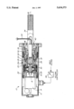
- the drawing which illustrates a sectional view showing an actuator for converting rotational movement to a linear movement according to one embodiment of the present invention.
- the actuator 10 as shown in the drawing has a housing 12 which has at one end a rotary electric motor 14 attached by motor shaft 16 to an intermediate shaft 18 which forms part of a harmonic pancake drive gear 20.
- the drive gear 20 has a static side 22 which engages the housing 12 so that it cannot rotate or slide.
- An output connection 24 on the outside face 20a of the drive gear 20 rotates and is joined to a drive nut 26.
- the motor 14, drive gear 20 and drive nut 26 are all on a rotational longitudinal axis 28.
- the drive gear 20 reduces the rotational speed so that the drive nut 26 is rotated at a considerably lower speed than the motor shaft 16. While the drive nut 26 can rotate, it is held to the drive gear 20 by the output connection 24 and therefore cannot move linearly in the housing 12.
- An internal thread 30 is provided in the drive nut 26 which engages an external thread 32 of an output shaft 34.
- the output shaft 34 has a spline shoulder 36 wherein splines engage in a series of internal grooves 38 in the housing 12.
- the output shaft 34 is hollow and has a linear potentiometer 40 fixed therein with a wiring connection 42 leading out of an aperture in the output shaft 34 to a monitoring device to measure displacement.
- a sensor shaft 44 is positioned on the longitudinal axis 28 extending into the potentiometer 40 in the drive shaft from an end face of the intermediate shaft 18.
- a return spring 45 keeps the sensor shaft 44 pushed up to the end face of the intermediate shaft 18.
- the electric motor 14 has a defined hysteresis so that by varying the voltage to the motor by voltage controller 48, the maximum output torque from the motor is determined.
- the relationship between motor voltage and longitudinal force of the output shaft 34 is determined based upon gear ratio and type of motor.
- the linear movement of the output shaft 34 can be monitored by the potentiometer 40.
- an operator is aware as to the exact distance moved by the output shaft 34. If for example this distance is not the required distance but the motor 14 has cut out, then the operator knows that there may be another reason such as a blockage that prevents the desired movement.
- the outside diameter of the housing 12 is 60 mm and the electric motor 14 produces a force of 1,000 lbs. at 16 volts. In another embodiment the motor 14 produces 1,500 lbs. at 24 volts. No clutch is needed as setting the voltage to the motor 14 automatically limits the force available from the output shaft 34.
- variable voltage control is provided which is adjustable for different voltages representing different longitudinal forces on the output shaft 34.
- seal 46 is positioned at the end of the housing 12 sealing the housing 12 to the output shaft 34.
Landscapes
- Engineering & Computer Science (AREA)
- General Engineering & Computer Science (AREA)
- Mechanical Engineering (AREA)
- Connection Of Motors, Electrical Generators, Mechanical Devices, And The Like (AREA)
- Transmission Devices (AREA)
Abstract
Description
Claims (13)
Priority Applications (2)
| Application Number | Priority Date | Filing Date | Title |
|---|---|---|---|
| US08/506,079 US5634373A (en) | 1995-07-24 | 1995-07-24 | Rotational to linear movement actuator with limiter |
| CA002158624A CA2158624C (en) | 1995-07-24 | 1995-09-19 | Rotational to linear movement actuator with limiter |
Applications Claiming Priority (1)
| Application Number | Priority Date | Filing Date | Title |
|---|---|---|---|
| US08/506,079 US5634373A (en) | 1995-07-24 | 1995-07-24 | Rotational to linear movement actuator with limiter |
Publications (1)
| Publication Number | Publication Date |
|---|---|
| US5634373A true US5634373A (en) | 1997-06-03 |
Family
ID=24013090
Family Applications (1)
| Application Number | Title | Priority Date | Filing Date |
|---|---|---|---|
| US08/506,079 Expired - Lifetime US5634373A (en) | 1995-07-24 | 1995-07-24 | Rotational to linear movement actuator with limiter |
Country Status (2)
| Country | Link |
|---|---|
| US (1) | US5634373A (en) |
| CA (1) | CA2158624C (en) |
Cited By (15)
| Publication number | Priority date | Publication date | Assignee | Title |
|---|---|---|---|---|
| EP1083036A1 (en) * | 1999-09-07 | 2001-03-14 | Negri Bossi S.P.A. | Electric injection assembly for injection presses for plastic materials |
| US6310455B1 (en) * | 1999-04-19 | 2001-10-30 | Max Stegmann Gmbh Antriebstechnik-Elektronik | Positioning and actuating drive |
| US6563305B1 (en) * | 1998-01-23 | 2003-05-13 | Metso Automation Oy | Actuator of a paper or board machine including hall element position sensor |
| EP1324002A1 (en) * | 2001-12-28 | 2003-07-02 | ESW-EXTEL SYSTEMS WEDEL Gesellschaft für Ausrüstung mbH | Apparatus for measuring the actual length of an electromechanical linear drive |
| US20030121363A1 (en) * | 2000-05-25 | 2003-07-03 | Frank Poehlau | Harmonic drive |
| EP1561969A1 (en) * | 2004-02-09 | 2005-08-10 | Société industrielle de Sonceboz S.A. | Linear actuator |
| US20050174796A1 (en) * | 2004-02-09 | 2005-08-11 | Societe Industrielle De Sonceboz S.A. | Headlight positioning device |
| EP1587205A1 (en) * | 2004-04-14 | 2005-10-19 | Transrol | Linear actuator with a piston rod provided with a sensor |
| CN102112780A (en) * | 2009-05-13 | 2011-06-29 | 冲电气工业株式会社 | Reciprocating and rotary actuator |
| US9500476B2 (en) | 2012-07-27 | 2016-11-22 | Waterman Industries, Llc | Linear position monitoring system |
| US10030756B2 (en) * | 2016-06-02 | 2018-07-24 | Honeywell International Inc. | Automatic flight control actuator systems |
| US10106245B2 (en) | 2015-10-19 | 2018-10-23 | Honeywell International Inc. | Automatic flight control actuator systems |
| US10605342B2 (en) * | 2018-02-02 | 2020-03-31 | Aries Engineering Company, Inc. | Linear actuator with torque limiter mounted to a driven sprocket |
| US10888994B2 (en) * | 2018-05-02 | 2021-01-12 | California Institute Of Technology | Actuator for subsea and wet environments |
| US11218095B2 (en) * | 2018-11-12 | 2022-01-04 | Minebea Mitsumi Inc. | Method for controlling an actuator |
Citations (5)
| Publication number | Priority date | Publication date | Assignee | Title |
|---|---|---|---|---|
| US4716785A (en) * | 1985-08-20 | 1988-01-05 | Tokico Ltd. | Playback industrial robot provided with a driving device having an electric motor |
| US4833941A (en) * | 1986-01-24 | 1989-05-30 | Devron-Hercules Inc. | Air motor harmonic drive slice lip automation device |
| US4909099A (en) * | 1987-09-04 | 1990-03-20 | Windwinder Corporation | Rotary/linear actuator |
| US4951518A (en) * | 1990-08-28 | 1990-08-28 | Candy Mfg. Co., Inc. | Zero back lash phase adjusting mechanism |
| US5370011A (en) * | 1991-08-20 | 1994-12-06 | Harmonic Drive Antriebstechnik Gmbh | Positioning actuator |
-
1995
- 1995-07-24 US US08/506,079 patent/US5634373A/en not_active Expired - Lifetime
- 1995-09-19 CA CA002158624A patent/CA2158624C/en not_active Expired - Fee Related
Patent Citations (5)
| Publication number | Priority date | Publication date | Assignee | Title |
|---|---|---|---|---|
| US4716785A (en) * | 1985-08-20 | 1988-01-05 | Tokico Ltd. | Playback industrial robot provided with a driving device having an electric motor |
| US4833941A (en) * | 1986-01-24 | 1989-05-30 | Devron-Hercules Inc. | Air motor harmonic drive slice lip automation device |
| US4909099A (en) * | 1987-09-04 | 1990-03-20 | Windwinder Corporation | Rotary/linear actuator |
| US4951518A (en) * | 1990-08-28 | 1990-08-28 | Candy Mfg. Co., Inc. | Zero back lash phase adjusting mechanism |
| US5370011A (en) * | 1991-08-20 | 1994-12-06 | Harmonic Drive Antriebstechnik Gmbh | Positioning actuator |
Cited By (26)
| Publication number | Priority date | Publication date | Assignee | Title |
|---|---|---|---|---|
| US6563305B1 (en) * | 1998-01-23 | 2003-05-13 | Metso Automation Oy | Actuator of a paper or board machine including hall element position sensor |
| US6310455B1 (en) * | 1999-04-19 | 2001-10-30 | Max Stegmann Gmbh Antriebstechnik-Elektronik | Positioning and actuating drive |
| EP1083036A1 (en) * | 1999-09-07 | 2001-03-14 | Negri Bossi S.P.A. | Electric injection assembly for injection presses for plastic materials |
| US6443722B1 (en) | 1999-09-07 | 2002-09-03 | Negri Bossi S.P.A. | Electric injection assembly for injection presses for plastic materials |
| US6772655B2 (en) * | 2000-05-25 | 2004-08-10 | Oechsler Ag | Harmonic drive |
| US20030121363A1 (en) * | 2000-05-25 | 2003-07-03 | Frank Poehlau | Harmonic drive |
| KR100999231B1 (en) * | 2001-12-28 | 2010-12-07 | 이에스더블유 게엠바하 | An arrangement detecting for the current length of an electromechanical linear drive |
| EP1324002A1 (en) * | 2001-12-28 | 2003-07-02 | ESW-EXTEL SYSTEMS WEDEL Gesellschaft für Ausrüstung mbH | Apparatus for measuring the actual length of an electromechanical linear drive |
| US7218022B2 (en) | 2004-02-09 | 2007-05-15 | Société Industrielle de Sonceboz, S.A. | Linear actuator |
| EP1561969A1 (en) * | 2004-02-09 | 2005-08-10 | Société industrielle de Sonceboz S.A. | Linear actuator |
| US20050173994A1 (en) * | 2004-02-09 | 2005-08-11 | Societe Industrielle De Sonceboz Sa | Linear actuator |
| US20050174796A1 (en) * | 2004-02-09 | 2005-08-11 | Societe Industrielle De Sonceboz S.A. | Headlight positioning device |
| FR2866089A1 (en) * | 2004-02-09 | 2005-08-12 | Sonceboz Sa | LINEAR ACTUATOR |
| US7223001B2 (en) | 2004-02-09 | 2007-05-29 | Société Industrielle de Sonceboz, S.A. | Headlight positioning device |
| FR2869168A1 (en) * | 2004-04-14 | 2005-10-21 | Transrol Soc Par Actions Simpl | SENSING ACTUATOR WITH SENSOR ASSOCIATED WITH ITS STEM |
| US20060101929A1 (en) * | 2004-04-14 | 2006-05-18 | Laurent Benoit | Actuating cylinder with sensor associated with its rod |
| EP1587205A1 (en) * | 2004-04-14 | 2005-10-19 | Transrol | Linear actuator with a piston rod provided with a sensor |
| US7856900B2 (en) * | 2004-04-14 | 2010-12-28 | Transrol | Actuating cylinder with sensor associated with its rod |
| CN102112780A (en) * | 2009-05-13 | 2011-06-29 | 冲电气工业株式会社 | Reciprocating and rotary actuator |
| CN102112780B (en) * | 2009-05-13 | 2014-09-03 | 冲电气工业株式会社 | Reciprocating and rotary actuator |
| US9500476B2 (en) | 2012-07-27 | 2016-11-22 | Waterman Industries, Llc | Linear position monitoring system |
| US10106245B2 (en) | 2015-10-19 | 2018-10-23 | Honeywell International Inc. | Automatic flight control actuator systems |
| US10030756B2 (en) * | 2016-06-02 | 2018-07-24 | Honeywell International Inc. | Automatic flight control actuator systems |
| US10605342B2 (en) * | 2018-02-02 | 2020-03-31 | Aries Engineering Company, Inc. | Linear actuator with torque limiter mounted to a driven sprocket |
| US10888994B2 (en) * | 2018-05-02 | 2021-01-12 | California Institute Of Technology | Actuator for subsea and wet environments |
| US11218095B2 (en) * | 2018-11-12 | 2022-01-04 | Minebea Mitsumi Inc. | Method for controlling an actuator |
Also Published As
| Publication number | Publication date |
|---|---|
| CA2158624A1 (en) | 1997-01-25 |
| CA2158624C (en) | 2003-02-11 |
Similar Documents
| Publication | Publication Date | Title |
|---|---|---|
| US5634373A (en) | Rotational to linear movement actuator with limiter | |
| US5265488A (en) | Double-acting type dynamic back spacing removed driving system | |
| US4947070A (en) | Control apparatus | |
| US2860266A (en) | Linear actuator | |
| EP0832370B1 (en) | Servo-clutch control system | |
| US4898249A (en) | Rotary electric tool | |
| JP3574820B2 (en) | Differential linear actuator | |
| US4869139A (en) | Rotating driver with automatic speed and torque switching | |
| EP0851982B1 (en) | Improvements in electrically-operated disc brake assemblies for vehicles | |
| DE602006000779T2 (en) | Planetenreibradantriebsvorrichtung and steering device with such | |
| CA2076071A1 (en) | Positioning actuator | |
| US5101684A (en) | Stand-by drive operable by a crank handle | |
| US5127281A (en) | Composite motion guide device | |
| US4660431A (en) | Rotary motion linear actuator | |
| US4672858A (en) | Nut/clutch for linear actuator power screw | |
| EP0250609A1 (en) | Shiftable transmission motor drive with assured input-output relationship | |
| WO2001094088A3 (en) | Arrangement on granulating devices | |
| CA2125587A1 (en) | Integrated Anti-Backlash Gearhead Motor | |
| CN111221367B (en) | Control method of multifunctional actuator combining motor and controllable clutch | |
| US6726560B2 (en) | Dual power path drive for a rotating threshing rotor of an agricultural combine and method for re-engaging the same | |
| US5323888A (en) | Electrical actuated multi-speed drive apparatus | |
| US4836349A (en) | Clutch type tightening apparatus for allowing free adjustment of tightening force | |
| DE60010909T2 (en) | A linear and rotary drive device for mixing and pressing in molding machines | |
| EP0080026B1 (en) | Setting device for a controlled adjustment of a stop connected to an actuator | |
| US5285879A (en) | Electrical actuated multi-speed drive apparatus |
Legal Events
| Date | Code | Title | Description |
|---|---|---|---|
| AS | Assignment |
Owner name: MEASUREX DEVRON INC., CANADA Free format text: ASSIGNMENT OF ASSIGNORS INTEREST;ASSIGNORS:CUFFE, ALBERT ANTHONY;JORDI, WERNER E.;REEL/FRAME:007622/0278 Effective date: 19950720 |
|
| STCF | Information on status: patent grant |
Free format text: PATENTED CASE |
|
| FEPP | Fee payment procedure |
Free format text: PAYOR NUMBER ASSIGNED (ORIGINAL EVENT CODE: ASPN); ENTITY STATUS OF PATENT OWNER: LARGE ENTITY |
|
| FPAY | Fee payment |
Year of fee payment: 4 |
|
| FEPP | Fee payment procedure |
Free format text: PAYER NUMBER DE-ASSIGNED (ORIGINAL EVENT CODE: RMPN); ENTITY STATUS OF PATENT OWNER: LARGE ENTITY Free format text: PAYOR NUMBER ASSIGNED (ORIGINAL EVENT CODE: ASPN); ENTITY STATUS OF PATENT OWNER: LARGE ENTITY |
|
| FPAY | Fee payment |
Year of fee payment: 8 |
|
| FPAY | Fee payment |
Year of fee payment: 12 |