US5606732A - Direct connect radio and antenna assembly - Google Patents
Direct connect radio and antenna assembly Download PDFInfo
- Publication number
- US5606732A US5606732A US08/233,289 US23328994A US5606732A US 5606732 A US5606732 A US 5606732A US 23328994 A US23328994 A US 23328994A US 5606732 A US5606732 A US 5606732A
- Authority
- US
- United States
- Prior art keywords
- antenna
- radio
- card
- gps receiver
- substantially flat
- Prior art date
- Legal status (The legal status is an assumption and is not a legal conclusion. Google has not performed a legal analysis and makes no representation as to the accuracy of the status listed.)
- Expired - Lifetime
Links
- 238000000034 method Methods 0.000 claims description 9
- 239000004020 conductor Substances 0.000 claims description 7
- 230000008878 coupling Effects 0.000 claims description 7
- 238000010168 coupling process Methods 0.000 claims description 7
- 238000005859 coupling reaction Methods 0.000 claims description 7
- 238000004891 communication Methods 0.000 claims description 6
- 239000003989 dielectric material Substances 0.000 claims description 6
- 230000002829 reductive effect Effects 0.000 claims description 6
- 238000003780 insertion Methods 0.000 claims description 3
- 230000037431 insertion Effects 0.000 claims description 3
- 230000013011 mating Effects 0.000 claims description 3
- 230000006870 function Effects 0.000 claims description 2
- 239000002184 metal Substances 0.000 claims 2
- 229910010293 ceramic material Inorganic materials 0.000 claims 1
- 230000008030 elimination Effects 0.000 claims 1
- 238000003379 elimination reaction Methods 0.000 claims 1
- 230000005540 biological transmission Effects 0.000 description 6
- 238000007373 indentation Methods 0.000 description 5
- 230000015556 catabolic process Effects 0.000 description 4
- 238000006731 degradation reaction Methods 0.000 description 4
- 239000000047 product Substances 0.000 description 3
- 230000003321 amplification Effects 0.000 description 2
- 238000010276 construction Methods 0.000 description 2
- 238000013461 design Methods 0.000 description 2
- 238000005516 engineering process Methods 0.000 description 2
- 238000012423 maintenance Methods 0.000 description 2
- 239000007769 metal material Substances 0.000 description 2
- 238000003199 nucleic acid amplification method Methods 0.000 description 2
- 239000000758 substrate Substances 0.000 description 2
- RYGMFSIKBFXOCR-UHFFFAOYSA-N Copper Chemical compound [Cu] RYGMFSIKBFXOCR-UHFFFAOYSA-N 0.000 description 1
- 239000000853 adhesive Substances 0.000 description 1
- 230000001070 adhesive effect Effects 0.000 description 1
- 230000002411 adverse Effects 0.000 description 1
- 229910052782 aluminium Inorganic materials 0.000 description 1
- XAGFODPZIPBFFR-UHFFFAOYSA-N aluminium Chemical compound [Al] XAGFODPZIPBFFR-UHFFFAOYSA-N 0.000 description 1
- 230000000712 assembly Effects 0.000 description 1
- 238000000429 assembly Methods 0.000 description 1
- 239000000919 ceramic Substances 0.000 description 1
- 239000002131 composite material Substances 0.000 description 1
- 229910052802 copper Inorganic materials 0.000 description 1
- 239000010949 copper Substances 0.000 description 1
- 230000003247 decreasing effect Effects 0.000 description 1
- 230000000694 effects Effects 0.000 description 1
- 239000011152 fibreglass Substances 0.000 description 1
- 231100001261 hazardous Toxicity 0.000 description 1
- 238000009434 installation Methods 0.000 description 1
- 230000002452 interceptive effect Effects 0.000 description 1
- 230000000670 limiting effect Effects 0.000 description 1
- 239000000463 material Substances 0.000 description 1
- 238000004806 packaging method and process Methods 0.000 description 1
- 239000000126 substance Substances 0.000 description 1
- 239000013589 supplement Substances 0.000 description 1
- 230000000153 supplemental effect Effects 0.000 description 1
Images


Classifications
-
- H—ELECTRICITY
- H01—ELECTRIC ELEMENTS
- H01Q—ANTENNAS, i.e. RADIO AERIALS
- H01Q1/00—Details of, or arrangements associated with, antennas
- H01Q1/12—Supports; Mounting means
- H01Q1/22—Supports; Mounting means by structural association with other equipment or articles
- H01Q1/2258—Supports; Mounting means by structural association with other equipment or articles used with computer equipment
- H01Q1/2275—Supports; Mounting means by structural association with other equipment or articles used with computer equipment associated to expansion card or bus, e.g. in PCMCIA, PC cards, Wireless USB
-
- G—PHYSICS
- G01—MEASURING; TESTING
- G01S—RADIO DIRECTION-FINDING; RADIO NAVIGATION; DETERMINING DISTANCE OR VELOCITY BY USE OF RADIO WAVES; LOCATING OR PRESENCE-DETECTING BY USE OF THE REFLECTION OR RERADIATION OF RADIO WAVES; ANALOGOUS ARRANGEMENTS USING OTHER WAVES
- G01S19/00—Satellite radio beacon positioning systems; Determining position, velocity or attitude using signals transmitted by such systems
- G01S19/01—Satellite radio beacon positioning systems transmitting time-stamped messages, e.g. GPS [Global Positioning System], GLONASS [Global Orbiting Navigation Satellite System] or GALILEO
- G01S19/13—Receivers
- G01S19/35—Constructional details or hardware or software details of the signal processing chain
- G01S19/36—Constructional details or hardware or software details of the signal processing chain relating to the receiver frond end
-
- G—PHYSICS
- G01—MEASURING; TESTING
- G01S—RADIO DIRECTION-FINDING; RADIO NAVIGATION; DETERMINING DISTANCE OR VELOCITY BY USE OF RADIO WAVES; LOCATING OR PRESENCE-DETECTING BY USE OF THE REFLECTION OR RERADIATION OF RADIO WAVES; ANALOGOUS ARRANGEMENTS USING OTHER WAVES
- G01S19/00—Satellite radio beacon positioning systems; Determining position, velocity or attitude using signals transmitted by such systems
- G01S19/01—Satellite radio beacon positioning systems transmitting time-stamped messages, e.g. GPS [Global Positioning System], GLONASS [Global Orbiting Navigation Satellite System] or GALILEO
- G01S19/13—Receivers
- G01S19/35—Constructional details or hardware or software details of the signal processing chain
- G01S19/37—Hardware or software details of the signal processing chain
-
- H—ELECTRICITY
- H01—ELECTRIC ELEMENTS
- H01Q—ANTENNAS, i.e. RADIO AERIALS
- H01Q23/00—Antennas with active circuits or circuit elements integrated within them or attached to them
-
- Y—GENERAL TAGGING OF NEW TECHNOLOGICAL DEVELOPMENTS; GENERAL TAGGING OF CROSS-SECTIONAL TECHNOLOGIES SPANNING OVER SEVERAL SECTIONS OF THE IPC; TECHNICAL SUBJECTS COVERED BY FORMER USPC CROSS-REFERENCE ART COLLECTIONS [XRACs] AND DIGESTS
- Y10—TECHNICAL SUBJECTS COVERED BY FORMER USPC
- Y10S—TECHNICAL SUBJECTS COVERED BY FORMER USPC CROSS-REFERENCE ART COLLECTIONS [XRACs] AND DIGESTS
- Y10S439/00—Electrical connectors
- Y10S439/916—Antenna
Definitions
- the present invention relates to radio and antenna structures and connectors, and methods of implementing them.
- the present invention is directed to such structures, connectors, and methods for improving signal reception and transmission by a computer-based device which utilizes the global positioning system (GPS).
- GPS global positioning system
- the GPS is a space-based radio navigation system that provides worldwide, all-weather determinations of position, altitude, time and velocity.
- the GPS is implemented using a passive radio receiver and is available to a virtually unlimited number of users.
- the GPS radio receiver detects and receives precise reference signals from a constellation of 24 GPS satellites orbiting the earth.
- Low cost GPS receivers have been available for several years in specific GPS-dedicated products. Typically, these GPS application-specific products have included such basic computer components of a display, Keyboard, power supply, processor and housing. Accordingly, it has been recognized that portable computers and the like are an excellent platform to utilize GPS technology.
- PCMCIA Personal Computer Memory Card International Association
- PDA personal digital assistant
- Antenna placement has been found to raise certain issues with regard to the particular positioning configuration of the antenna to maximize visibility of the antenna to the GPS satellites, yet minimize cumbersome external components and cables. Although such considerations are evident in a variety of wireless communications applications, an effective antenna placement and mounting structure has yet to be developed which provides for both simple and easy mounting and removal, while concurrently maximizing signal reception and quality.
- Coaxial cables tend to introduce undesirable signal degradation attributable to signal attenuation through the cable, added receiver system noise, as well as reflection losses attributable to mismatched impedances. Reflection losses are apparent transmission losses across the cable which result when the impedance of a load, e.g., an antenna, is mismatched with that of a generator, such as a radio transmitter. Consequently, transmission losses on the line result when a portion of the energy is reflected due to the discontinuity of the mismatched impedances in the transmission line.
- a load e.g., an antenna
- a conventional cable configuration may include a GPS radio receiver 100 coupled to a PCMCIA interface 102 via a cable arrangement, as illustrated in FIG. 1.
- the PCMCIA interface 102 is coupled to the GPS receiver 100 by a serial interface port cable 104.
- a patch-type antenna 106 is coupled to the receiver 100 via a coaxial cable and connector arrangement 108.
- this coaxial cable arrangement 108 may introduce reflection and transmission losses of approximately 2.5 dB to 5 dB maximum at 1575 megahertz (MHz).
- MHz megahertz
- a radio is directly coupled to a computer via a plug-in connection or receiving slot such as a PCMCIA interface slot.
- An antenna is mounted on the top surface of the radio via a coaxial connector having a first part and a second part.
- the antenna has a substantially flat bottom surface to which is coupled the first part of the coaxial connector.
- the second part of the coaxial connector is affixed to the top surface of the radio. Accordingly, when the first and second parts of the coaxial connector are affixed to the corresponding surfaces of the antenna and the radio, the top surface of the radio directly faces and is adjacent to the bottom surface of the antenna.
- the antenna comprises a patch-type antenna element having a size and shape that conforms to and is compatible with the size and shape of the radio.
- the patch antenna may be rigid or malleable, depending upon the particular radio operating conditions.
- the second part of the coaxial connector, which is coupled to the top surface of the radio is contained in an indent in the surface of the radio, and the first part of the coaxial connector coupled to the bottom surface of the patch antenna mates directly to the second part of the coaxial connector. Accordingly, the need for external and internal coaxial cables is eliminated, while signal degradation and losses inherently produced when using such cables can be significantly reduced.
- FIG. 1 is a perspective view of a prior art antenna arrangement.
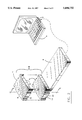
- FIG. 2 is a perspective view of a direct connect antenna according to a preferred embodiment of the present invention.
- FIG. 3 is a side cross-sectional view of a mounted direct connect antenna along lines 3--3 indicated in the embodiment of FIG. 2.
- FIG. 4 is a perspective view of an alternate embodiment of the present invention.
- a direct connect radio and antenna structure in accordance with an embodiment of the present invention is indicated generally at 10 in FIG. 2.
- the radio and antenna configuration includes a radio coupled to a plug-in computer-adaptable module or card 16, such as a PCMCIA interface card, and a directly connectable antenna 12.
- the radio component 14 comprises a GPS radio receiver.
- the receiver 14 may be directly coupled to a patch-type antenna 12.
- embodiments of the present invention provide GPS receiver capabilities embedded within a PCMCIA format.
- Antenna embodiments of the present invention provide for substantially reduced RF signal degradation typically attributable to distributed cable losses and attenuation introduced by conventional antenna cable arrangements.
- coaxial cables are typical sources of cable losses.
- embodiments of the present invention are directed to decreasing the amount and effects of coaxial cable reflection losses and distributed losses by eliminating unnecessary cabling. Consequently, the need to match the characteristic impedances of the interconnected components is likewise eliminated.
- embodiments of the present invention provide for an integrated antenna arrangement which allows for uncomplicated mounting of the antenna to a radio, and immediate installation of the integrated PCMCIA card and radio within the host computer.
- preferred embodiments of the present invention include a patch-type antenna 12 which can be directly coupled to a GPS radio receiver 14.
- the receiver 14 is coupled to and extends from a PCMCIA memory interface card 16.
- the antenna 12 may be mounted on, and thus supported by, the GPS receiver 14, as illustrated in FIGS. 2 and 3.
- the PC card 16 is an extended-form PCMCIA compliant Type II interface and is approximately half as thick as the GPS receiver 14.
- the PCMCIA card 16 may be thicker or thinner than that shown.
- the PC card 16 includes an application specific integrated circuit (ASIC), a universal asynchronous receiver transmitter (UART), and a read only memory (ROM).
- ASIC application specific integrated circuit
- UART universal asynchronous receiver transmitter
- ROM read only memory
- the ASIC for example, performs logic functions necessary for particular applications to interface the PCMCIA standard with the host computer 15.
- the UART provides a means of converting the serial data to a digital parallel format across a PCMCIA bus (not shown). When configured according to the standard communications port addresses, the UART acts as a standard serial interface.
- the antenna 12 is mounted to the radio receiver 14 via a two-part coaxial connector 18 and 20.
- Half of the coaxial connector 18, e.g., the male or female part, is defined on one surface of the antenna 12.
- the opposing part of the coaxial connector 20 is formed in an adjacent surface of the GPS receiver.
- the male and female components 18 and 20 of the coaxial connector are affixed to the antenna 12 and GPS receiver 14, respectively.
- the female component 18 is mounted to the underside 24 of the antenna 12.
- the female component 18 protrudes from the lower surface 24 of the antenna 12 for coupling with the male component 20 formed in the upper surface 22 of the GPS receiver 14.
- the male connector 20 is formed as an indent in the upper surface 22 of the receiver 14. In this way, the protruding female connector 18 can be quickly and simply inserted into the male connector 20 to provide a tight snap-fit in which little or no space is left between the surfaces 24 and 22 of the antenna 12 and the receiver 14, respectively.
- Such an arrangement allows minimal movement and shifting of the antenna relative to the GPS receiver and, consequently, substantially reduces the potential for breakage or loss of the received radio frequency (RF) signal.
- the particular connector configuration provides a repeatable ground plane for the antenna.
- the arrangement of the male and female coaxial connector components may be reversed, such that the male component is attached to the antenna, while the female component is coupled to the GPS receiver.
- either the male or female coaxial connector part may protrude from or be contained within its respective mounting surface.
- the male connector may be mounted to the lower surface 24 of the antenna 12 and protrude therefrom for insertion into an associated female connector defined within the upper surface 22 of the GPS receiver 14.
- connection arrangements in addition to coaxial connectors, may be used.
- the radio and antenna may be directly connected via single conductor cabling.
- the radio and antenna may be connected directly by a single line connection scheme.
- the male and female coaxial connectors may both be arranged to protrude slightly from the lower and upper surfaces of the antenna and the GPS receiver 14, respectively.
- the antenna 12 may be thinner than the GPS receiver 14, the connector component carried by the antenna 12 is preferably externally attached or otherwise protrudes from the lower surface 24 of the antenna 12. Such construction is preferred to avoid interference between the coaxial connector attachment and the antenna element disposed within the antenna 12.
- the antenna 12 is a patch-type antenna in which a metal material 13, such as copper, aluminum, or a composite substance, is bonded to opposite sides of a high-dielectric material (not shown) and encased within a radome structure 26.
- the dielectric material may comprise a ceramic or fiberglass substrate.
- the external surface of the metal material 13, which receives the RF signals, is etched to obtain the optimum receiving characteristics based on the dielectric constant of the materials used to form the substrate and the radome, the size of the patch element 13, and the received frequency. This arrangement helps to prevent resonant frequency drift with temperature variations. Consequently, the signal reception area may be maximized, while the antenna size and unnecessary protrusion are reduced.
- the coaxial connector components 18 and 20 are preferably mounted on the lower and upper surfaces of the antenna and GPS receiver, respectively. Accordingly, the female connector 18 is in contact with the internal conductive material of the antenna 12.
- the male connector 20, which is coupled to an RF interface (not shown) internal to the GPS receiver 14, can then be mated to the female connector 18 with the respective surfaces of the antenna 12 and the receiver 14 facing each other.
- Supplemental fastening devices and interconnecting structures may be implemented to secure the antenna 12 to the receiver 14.
- multiple indentations 40 are provided about the periphery of the antenna 12 for slidable mating with associated receiving slots 42 formed along the sides of the receiver 14.
- the indentation/slot structures act as guides to provide an uncomplicated means of aligning and coupling the two connector halves 18 and 20 together. Furthermore, such alignment prevents mismatching of the connector halves and possible connector damage. Accordingly, a user can easily attach the antenna to the receiver.
- the antenna can be quickly mounted and secured to the receiver without requiring extra careful attention to accurately match together the coaxial connector halves 18 and 20.
- the configuration and structure of the indentation and slot arrangement are particularly described, it will be recognized, however, that a variety of guide or alignment configurations may be employed.
- the antenna 12 may be mounted to the GPS receiver 14 by screws or other semi-permanent devices which supplement the snap-in connection provided by the coaxial connector. Screws generally will not detune the antenna as long as proper design criteria are followed. Such means of affixing the antenna to the GPS receiver or to another object is preferred if permanent or rigid antenna attachment is desired. In still further embodiments, different means such as an adhesive and the like may be used to secure the antenna to the GPS receiver.
- the upper exposed surface of the radome 26 comprises a curved shape, with the underside being relatively flat to conform to the shape of the GPS receiver 14, it will be recognized that other antenna shapes, configurations, and arrangements may be implemented.
- the antenna may be completely flat to minimize wind resistance, e.g., for use in or on a moving vehicle, or malleable to fit around or within limited, defined spaces.
- the antenna may have a variety of shapes or configurations to accommodate the receiver structure and mounting arrangement.
- the antenna 12 has an L-shape which conforms to one of the upper edges of the receiver 14.
- the male and female coaxial connector components may be coupled to either the underside 24 of the antenna 12 and the upper surface 22 of the receiver 14.
- the numerical references to the various elements of FIG. 4 are coincident with those of FIGS. 2 and 3 to indicate that, preferably, the shape of the antenna structure 12 should not affect the direct coupling arrangement of the antenna to the receiver.
- the patch antenna is tuned to match the net impedance of the antenna elements, including the dielectric material, ground plane and receiver input impedance to maximize the signal received by the GPS receiver 14.
- a constant impedance value is matched between the antenna and the GPS receiver.
- While the illustrated embodiment employs a GPS receiver which is thicker than the standard Type II PCMCIA interface card, it will be recognized that further embodiments may employ a substantially thinner or smaller GPS receiver, such that the entire unit can be inserted into the Type II slot.
- the memory card and GPS receiver may be permanently hard-wired into the host computer. The patch antenna may then be directly connected to the receiver components carried within the host computer.
Abstract
Description
Claims (17)
Priority Applications (3)
| Application Number | Priority Date | Filing Date | Title |
|---|---|---|---|
| US08/233,289 US5606732A (en) | 1994-04-26 | 1994-04-26 | Direct connect radio and antenna assembly |
| EP95101846A EP0680112A3 (en) | 1994-04-26 | 1995-02-10 | Direct connect radio and antenna assembly. |
| JP7101250A JPH07303052A (en) | 1994-04-26 | 1995-04-25 | Apparatus and improuing method for radiocommunication |
Applications Claiming Priority (1)
| Application Number | Priority Date | Filing Date | Title |
|---|---|---|---|
| US08/233,289 US5606732A (en) | 1994-04-26 | 1994-04-26 | Direct connect radio and antenna assembly |
Publications (1)
| Publication Number | Publication Date |
|---|---|
| US5606732A true US5606732A (en) | 1997-02-25 |
Family
ID=22876655
Family Applications (1)
| Application Number | Title | Priority Date | Filing Date |
|---|---|---|---|
| US08/233,289 Expired - Lifetime US5606732A (en) | 1994-04-26 | 1994-04-26 | Direct connect radio and antenna assembly |
Country Status (3)
| Country | Link |
|---|---|
| US (1) | US5606732A (en) |
| EP (1) | EP0680112A3 (en) |
| JP (1) | JPH07303052A (en) |
Cited By (59)
| Publication number | Priority date | Publication date | Assignee | Title |
|---|---|---|---|---|
| US5832247A (en) * | 1995-12-28 | 1998-11-03 | Trimble Navigation Limited | PCI card for receiving a GPS signal |
| US5955974A (en) * | 1997-09-11 | 1999-09-21 | Fujitsu Limited | Information processing apparatus with transfer or arrival precaution |
| US5987547A (en) * | 1997-03-31 | 1999-11-16 | Texas Instruments Incorporated | Network computer with interchangeable hard drive and data transceiver |
| US5990846A (en) * | 1998-05-28 | 1999-11-23 | Intel Corporation | Self-aligning global positioning system antenna |
| US6008774A (en) * | 1997-03-21 | 1999-12-28 | Celestica International Inc. | Printed antenna structure for wireless data communications |
| US6018784A (en) * | 1997-07-31 | 2000-01-25 | Trimble Navigation Limited | PCI card for receiving a GPS signal |
| US6072991A (en) * | 1996-09-03 | 2000-06-06 | Raytheon Company | Compact microwave terrestrial radio utilizing monolithic microwave integrated circuits |
| US6104620A (en) * | 1993-12-23 | 2000-08-15 | Symbol Technologies, Inc. | Shielded radio card assembly |
| US6150961A (en) * | 1998-11-24 | 2000-11-21 | International Business Machines Corporation | Automated traffic mapping |
| US6208506B1 (en) | 1999-05-19 | 2001-03-27 | Gei-Jon Pao | Space saving CD-ROM/DVD drive mechanism used with electronic devices |
| US6286063B1 (en) | 1998-06-08 | 2001-09-04 | Sonigistix Corporation | Microprocessor-controlled broadcast receiver embedded in an external peripheral with digital communications interface for bi-directional communication with a computer remotely located |
| US6295031B1 (en) | 1993-12-23 | 2001-09-25 | Symbol Technologies, Inc. | Memory card assembly having an integral antenna |
| US6333703B1 (en) | 1998-11-24 | 2001-12-25 | International Business Machines Corporation | Automated traffic mapping using sampling and analysis |
| US6348893B1 (en) * | 1999-05-07 | 2002-02-19 | Nokia Mobile Phones Ltd. | Antenna structure of an expansion card for an electronic device |
| US6351388B1 (en) * | 1997-11-21 | 2002-02-26 | Xybernaut Corporation | Mobile computer with PC housing for PC card and dongle |
| US6407709B1 (en) * | 1999-07-16 | 2002-06-18 | Garmin Corporation | Mounting device with integrated antenna |
| US6434648B1 (en) | 1998-12-10 | 2002-08-13 | Smart Modular Technologies, Inc. | PCMCIA compatible memory card with serial communication interface |
| US6437745B1 (en) * | 1999-10-20 | 2002-08-20 | Nokia Corporation | Expansion card for wireless data transmission and antenna structure for the same |
| US6480146B1 (en) * | 2001-11-29 | 2002-11-12 | Palm, Inc. | Intermittent use of a port in response to location data push |
| US20020169608A1 (en) * | 1999-10-04 | 2002-11-14 | Comsense Technologies Ltd. | Sonic/ultrasonic authentication device |
| WO2002100124A1 (en) * | 2001-06-04 | 2002-12-12 | Gordon Novel | Pc card for use in a telecommunications system |
| US6522299B2 (en) * | 1999-04-08 | 2003-02-18 | Cypress Semiconductor Corp. | PC card retractable antenna |
| US6525932B1 (en) | 1999-08-18 | 2003-02-25 | Fujitsu Limited | Expansion unit and electronic apparatus |
| US20030054856A1 (en) * | 2001-09-19 | 2003-03-20 | Glover Kenneth Matthew | All-in-one modular wireless device |
| US6556170B2 (en) | 2001-04-02 | 2003-04-29 | Fci Americas Technology, Inc. | Retractable and rotatable antenna for an electronic card |
| US20030099088A1 (en) * | 2001-11-23 | 2003-05-29 | Sumsung Electronics Co., Ltd. | Portable computer mounted with wireless LAN card |
| US20030144031A1 (en) * | 2001-02-26 | 2003-07-31 | Yasushi Ono | Communication card and communication device |
| US6607136B1 (en) | 1998-09-16 | 2003-08-19 | Beepcard Inc. | Physical presence digital authentication system |
| US20030176179A1 (en) * | 2002-03-18 | 2003-09-18 | Ken Hersey | Wireless local area network and antenna used therein |
| US20040027299A1 (en) * | 2001-03-13 | 2004-02-12 | Peter Sjoblom | Antenna device |
| US6693592B2 (en) | 2000-12-22 | 2004-02-17 | The Charles Stark Draper Laboratory, Inc. | Geographical navigation using multipath wireless navigation signals |
| US20040192075A1 (en) * | 2003-03-28 | 2004-09-30 | Yi-Hua Lu | Wireless interconnect device |
| US20040204102A1 (en) * | 2002-03-05 | 2004-10-14 | Kuehnel Thomas W. | Detachable radio module |
| US20040236819A1 (en) * | 2001-03-22 | 2004-11-25 | Beepcard Inc. | Method and system for remotely authenticating identification devices |
| US20050119029A1 (en) * | 1993-04-27 | 2005-06-02 | Kinney Patrick W. | Radio card having independent antenna interface supporting antenna diversity |
| US6928302B1 (en) * | 1993-04-27 | 2005-08-09 | Broadcom Corporation | Radio card having independent antenna interface supporting antenna diversity |
| US20050235086A1 (en) * | 1999-05-11 | 2005-10-20 | Mills Kevin J | Portable GPS methods and devices |
| US20050285800A1 (en) * | 2004-06-29 | 2005-12-29 | Reece John K | Antennae attachable to an electronic device enclosure or other structure |
| US20060058941A1 (en) * | 1999-04-19 | 2006-03-16 | Dekock Bruce W | System for providing traffic information |
| US20060114160A1 (en) * | 2004-11-29 | 2006-06-01 | Lexmark International, Inc. | Snap-in antenna assembly for wireless radio circuit card |
| US20060136544A1 (en) * | 1998-10-02 | 2006-06-22 | Beepcard, Inc. | Computer communications using acoustic signals |
| US7183929B1 (en) | 1998-07-06 | 2007-02-27 | Beep Card Inc. | Control of toys and devices by sounds |
| US7260221B1 (en) | 1998-11-16 | 2007-08-21 | Beepcard Ltd. | Personal communicator authentication |
| US7334735B1 (en) | 1998-10-02 | 2008-02-26 | Beepcard Ltd. | Card for interaction with a computer |
| US20080094279A1 (en) * | 2004-08-18 | 2008-04-24 | Koninklijke Philips Electronics N.V. | GPS Receiver And Related Method And Apparatus |
| US20080125145A1 (en) * | 1992-11-09 | 2008-05-29 | Adc Technology Inc. | Portable communicator |
| US20090102707A1 (en) * | 2005-01-19 | 2009-04-23 | Elwell Jr John M | Systems and methods for transparency mapping using multipath signals |
| US20090102711A1 (en) * | 2005-01-19 | 2009-04-23 | Elwell Jr John M | Systems and methods for transparency mapping using multipath signals |
| US20090287870A1 (en) * | 1999-05-11 | 2009-11-19 | Mills Kevin J | Removable wireless expansion card having a removable subscriber information module |
| US7679561B2 (en) | 2005-01-19 | 2010-03-16 | The Charles Stark Draper Laboratory, Inc. | Systems and methods for positioning using multipath signals |
| US7908080B2 (en) | 2004-12-31 | 2011-03-15 | Google Inc. | Transportation routing |
| US20110191000A1 (en) * | 2010-02-01 | 2011-08-04 | Bendix Commercial Vehicle Systems Llc | Engine control request from adaptive control with braking controller |
| US8019609B2 (en) | 1999-10-04 | 2011-09-13 | Dialware Inc. | Sonic/ultrasonic authentication method |
| US8606461B2 (en) | 2011-12-09 | 2013-12-10 | Bendix Commercial Vehicle Systems Llc | System and method for monitoring tire status |
| US8907774B2 (en) | 2011-03-01 | 2014-12-09 | Bendix Commercial Vehicle Systems Llc | System and method for monitoring tire condition |
| EP2884581A1 (en) * | 2013-12-10 | 2015-06-17 | Alcatel-Lucent Shanghai Bell Co., Ltd. | Radome and antenna system housing |
| US9067466B2 (en) | 2013-01-30 | 2015-06-30 | Bendix Commercial Vehicle Systems Llc | Diversity antenna |
| EP3261171A4 (en) * | 2015-02-19 | 2018-08-29 | Tokyo Cosmos Electric Co., Ltd. | Antenna and communication device |
| US11614545B2 (en) * | 2020-03-26 | 2023-03-28 | Novatel Inc. | Systems and methods for utilizing a connector with an external antenna to utilize multifrequency GNSS functionality of a mobile device |
Families Citing this family (9)
| Publication number | Priority date | Publication date | Assignee | Title |
|---|---|---|---|---|
| GB9501506D0 (en) * | 1995-01-26 | 1995-03-15 | Symbionics Dev Ltd | Antennas |
| KR100408264B1 (en) * | 1996-08-21 | 2004-04-14 | 삼성전자주식회사 | Computer |
| FR2753569B1 (en) * | 1996-09-16 | 1998-10-09 | Alcatel Espace | RADIANT ELEMENT DEVICE |
| GB2320815B (en) * | 1996-12-23 | 2001-12-12 | Nokia Mobile Phones Ltd | Antenna assembly |
| GB2357189B (en) * | 1999-11-15 | 2001-11-07 | Psion Connect Ltd | Removable wireless device |
| JP2001237625A (en) * | 2000-02-21 | 2001-08-31 | Sony Corp | Radio communication equipment |
| KR100443707B1 (en) * | 2001-06-05 | 2004-08-09 | 정동회 | Compact Flash Type GPS Receiver |
| EP1589680B1 (en) * | 2004-02-17 | 2008-02-27 | Matsushita Electric Works, Ltd | Antenna unit |
| US20100138155A1 (en) * | 2008-12-02 | 2010-06-03 | Sterling Du | Notebook computers with integrated satellite navigation systems |
Citations (10)
| Publication number | Priority date | Publication date | Assignee | Title |
|---|---|---|---|---|
| JPS59178511A (en) * | 1983-03-30 | 1984-10-09 | Hitachi Ltd | Setting-up structure of electronic apparatus or the like |
| JPH02246402A (en) * | 1989-03-17 | 1990-10-02 | Matsushita Electric Ind Co Ltd | Antenna system |
| US4980694A (en) * | 1989-04-14 | 1990-12-25 | Goldstar Products Company, Limited | Portable communication apparatus with folded-slot edge-congruent antenna |
| US5007863A (en) * | 1990-09-17 | 1991-04-16 | Jialuo Xuan | Module-type multi-function electrical power adapter for automobiles and the like |
| US5198824A (en) * | 1992-01-17 | 1993-03-30 | Texas Instruments Incorporated | High temperature co-fired ceramic integrated phased array packaging |
| US5335276A (en) * | 1992-12-16 | 1994-08-02 | Texas Instruments Incorporated | Communication system and methods for enhanced information transfer |
| US5361061A (en) * | 1992-10-19 | 1994-11-01 | Motorola, Inc. | Computer card data receiver having a foldable antenna |
| US5373149A (en) * | 1993-02-01 | 1994-12-13 | At&T Bell Laboratories | Folding electronic card assembly |
| US5391094A (en) * | 1992-11-20 | 1995-02-21 | Murata Mfg. Co., Ltd. | Card-type line interface device |
| US5470233A (en) * | 1994-03-17 | 1995-11-28 | Arkenstone, Inc. | System and method for tracking a pedestrian |
Family Cites Families (6)
| Publication number | Priority date | Publication date | Assignee | Title |
|---|---|---|---|---|
| US5272485A (en) * | 1992-02-04 | 1993-12-21 | Trimble Navigation Limited | Microstrip antenna with integral low-noise amplifier for use in global positioning system (GPS) receivers |
| US5239669A (en) * | 1992-02-04 | 1993-08-24 | Trimble Navigation Limited | Coupler for eliminating a hardwire connection between a handheld global positioning system (GPS) receiver and a stationary remote antenna |
| GB9203002D0 (en) * | 1992-02-12 | 1992-03-25 | Secr Defence | Navigational equipment |
| JPH06314924A (en) * | 1993-04-19 | 1994-11-08 | Wireless Access Inc | Partly shorted microstrip antenna |
| CA2161675A1 (en) * | 1993-04-27 | 1994-11-10 | Patrick W. Kinney | Multiple antenna selection and antenna cap for computer devices utilizing radio and modem cards |
| WO1994028379A1 (en) * | 1993-05-28 | 1994-12-08 | Trimble Navigation Limited | Combined pc/104 and satellite positioning system |
-
1994
- 1994-04-26 US US08/233,289 patent/US5606732A/en not_active Expired - Lifetime
-
1995
- 1995-02-10 EP EP95101846A patent/EP0680112A3/en not_active Withdrawn
- 1995-04-25 JP JP7101250A patent/JPH07303052A/en not_active Withdrawn
Patent Citations (10)
| Publication number | Priority date | Publication date | Assignee | Title |
|---|---|---|---|---|
| JPS59178511A (en) * | 1983-03-30 | 1984-10-09 | Hitachi Ltd | Setting-up structure of electronic apparatus or the like |
| JPH02246402A (en) * | 1989-03-17 | 1990-10-02 | Matsushita Electric Ind Co Ltd | Antenna system |
| US4980694A (en) * | 1989-04-14 | 1990-12-25 | Goldstar Products Company, Limited | Portable communication apparatus with folded-slot edge-congruent antenna |
| US5007863A (en) * | 1990-09-17 | 1991-04-16 | Jialuo Xuan | Module-type multi-function electrical power adapter for automobiles and the like |
| US5198824A (en) * | 1992-01-17 | 1993-03-30 | Texas Instruments Incorporated | High temperature co-fired ceramic integrated phased array packaging |
| US5361061A (en) * | 1992-10-19 | 1994-11-01 | Motorola, Inc. | Computer card data receiver having a foldable antenna |
| US5391094A (en) * | 1992-11-20 | 1995-02-21 | Murata Mfg. Co., Ltd. | Card-type line interface device |
| US5335276A (en) * | 1992-12-16 | 1994-08-02 | Texas Instruments Incorporated | Communication system and methods for enhanced information transfer |
| US5373149A (en) * | 1993-02-01 | 1994-12-13 | At&T Bell Laboratories | Folding electronic card assembly |
| US5470233A (en) * | 1994-03-17 | 1995-11-28 | Arkenstone, Inc. | System and method for tracking a pedestrian |
Non-Patent Citations (5)
| Title |
|---|
| Micro Pulse, L1 GPS Airborne Antenna, Miniarinc, Aug. 1993. * |
| Micro Pulse, L1 GPS Lightweight Survey Antenna, Jul. 1993. * |
| Mobile Office, "How to Upgrade Your Cellular Phone in Two Easy Steps", Jan. 1993. |
| Mobile Office, How to Upgrade Your Cellular Phone in Two Easy Steps , Jan. 1993. * |
| Socket, Global Positioning System Antenna Cable, 1993. * |
Cited By (111)
| Publication number | Priority date | Publication date | Assignee | Title |
|---|---|---|---|---|
| US8103313B2 (en) | 1992-11-09 | 2012-01-24 | Adc Technology Inc. | Portable communicator |
| US20080125145A1 (en) * | 1992-11-09 | 2008-05-29 | Adc Technology Inc. | Portable communicator |
| US7953444B2 (en) | 1993-04-27 | 2011-05-31 | Broadcom Corporation | Radio card having independent antenna interface supporting antenna diversity |
| US20050119029A1 (en) * | 1993-04-27 | 2005-06-02 | Kinney Patrick W. | Radio card having independent antenna interface supporting antenna diversity |
| US6928302B1 (en) * | 1993-04-27 | 2005-08-09 | Broadcom Corporation | Radio card having independent antenna interface supporting antenna diversity |
| US7469150B2 (en) | 1993-04-27 | 2008-12-23 | Broadcom Corporation | Radio card having independent antenna interface supporting antenna diversity |
| US20090167618A1 (en) * | 1993-04-27 | 2009-07-02 | Broadcom Corporation | Radio card having independent antenna interface supporting antenna diversity |
| US6295031B1 (en) | 1993-12-23 | 2001-09-25 | Symbol Technologies, Inc. | Memory card assembly having an integral antenna |
| US6104620A (en) * | 1993-12-23 | 2000-08-15 | Symbol Technologies, Inc. | Shielded radio card assembly |
| US5832247A (en) * | 1995-12-28 | 1998-11-03 | Trimble Navigation Limited | PCI card for receiving a GPS signal |
| US6072991A (en) * | 1996-09-03 | 2000-06-06 | Raytheon Company | Compact microwave terrestrial radio utilizing monolithic microwave integrated circuits |
| US6008774A (en) * | 1997-03-21 | 1999-12-28 | Celestica International Inc. | Printed antenna structure for wireless data communications |
| US5987547A (en) * | 1997-03-31 | 1999-11-16 | Texas Instruments Incorporated | Network computer with interchangeable hard drive and data transceiver |
| US6018784A (en) * | 1997-07-31 | 2000-01-25 | Trimble Navigation Limited | PCI card for receiving a GPS signal |
| US5955974A (en) * | 1997-09-11 | 1999-09-21 | Fujitsu Limited | Information processing apparatus with transfer or arrival precaution |
| US6351388B1 (en) * | 1997-11-21 | 2002-02-26 | Xybernaut Corporation | Mobile computer with PC housing for PC card and dongle |
| US5990846A (en) * | 1998-05-28 | 1999-11-23 | Intel Corporation | Self-aligning global positioning system antenna |
| US6286063B1 (en) | 1998-06-08 | 2001-09-04 | Sonigistix Corporation | Microprocessor-controlled broadcast receiver embedded in an external peripheral with digital communications interface for bi-directional communication with a computer remotely located |
| US7183929B1 (en) | 1998-07-06 | 2007-02-27 | Beep Card Inc. | Control of toys and devices by sounds |
| US20100256976A1 (en) * | 1998-09-16 | 2010-10-07 | Beepcard Ltd. | Physical presence digital authentication system |
| US9607475B2 (en) | 1998-09-16 | 2017-03-28 | Dialware Inc | Interactive toys |
| US7568963B1 (en) | 1998-09-16 | 2009-08-04 | Beepcard Ltd. | Interactive toys |
| US20090264205A1 (en) * | 1998-09-16 | 2009-10-22 | Beepcard Ltd. | Interactive toys |
| US7706838B2 (en) | 1998-09-16 | 2010-04-27 | Beepcard Ltd. | Physical presence digital authentication system |
| US8843057B2 (en) | 1998-09-16 | 2014-09-23 | Dialware Inc. | Physical presence digital authentication system |
| US20110034251A1 (en) * | 1998-09-16 | 2011-02-10 | Beepcard Ltd. | Interactive toys |
| US8509680B2 (en) | 1998-09-16 | 2013-08-13 | Dialware Inc. | Physical presence digital authentication system |
| US6607136B1 (en) | 1998-09-16 | 2003-08-19 | Beepcard Inc. | Physical presence digital authentication system |
| US8425273B2 (en) | 1998-09-16 | 2013-04-23 | Dialware Inc. | Interactive toys |
| US9275517B2 (en) | 1998-09-16 | 2016-03-01 | Dialware Inc. | Interactive toys |
| US8078136B2 (en) | 1998-09-16 | 2011-12-13 | Dialware Inc. | Physical presence digital authentication system |
| US20040031856A1 (en) * | 1998-09-16 | 2004-02-19 | Alon Atsmon | Physical presence digital authentication system |
| US9830778B2 (en) | 1998-09-16 | 2017-11-28 | Dialware Communications, Llc | Interactive toys |
| US8062090B2 (en) | 1998-09-16 | 2011-11-22 | Dialware Inc. | Interactive toys |
| US9361444B2 (en) | 1998-10-02 | 2016-06-07 | Dialware Inc. | Card for interaction with a computer |
| US8544753B2 (en) | 1998-10-02 | 2013-10-01 | Dialware Inc. | Card for interaction with a computer |
| US20060136544A1 (en) * | 1998-10-02 | 2006-06-22 | Beepcard, Inc. | Computer communications using acoustic signals |
| US7480692B2 (en) | 1998-10-02 | 2009-01-20 | Beepcard Inc. | Computer communications using acoustic signals |
| US7941480B2 (en) | 1998-10-02 | 2011-05-10 | Beepcard Inc. | Computer communications using acoustic signals |
| US7334735B1 (en) | 1998-10-02 | 2008-02-26 | Beepcard Ltd. | Card for interaction with a computer |
| US20110182445A1 (en) * | 1998-10-02 | 2011-07-28 | Beepcard Inc. | Computer communications using acoustic signals |
| US20080173717A1 (en) * | 1998-10-02 | 2008-07-24 | Beepcard Ltd. | Card for interaction with a computer |
| US7383297B1 (en) | 1998-10-02 | 2008-06-03 | Beepcard Ltd. | Method to use acoustic signals for computer communications |
| US20090067291A1 (en) * | 1998-10-02 | 2009-03-12 | Beepcard Inc. | Computer communications using acoustic signals |
| US8935367B2 (en) | 1998-10-02 | 2015-01-13 | Dialware Inc. | Electronic device and method of configuring thereof |
| US7260221B1 (en) | 1998-11-16 | 2007-08-21 | Beepcard Ltd. | Personal communicator authentication |
| US6333703B1 (en) | 1998-11-24 | 2001-12-25 | International Business Machines Corporation | Automated traffic mapping using sampling and analysis |
| US6150961A (en) * | 1998-11-24 | 2000-11-21 | International Business Machines Corporation | Automated traffic mapping |
| US6434648B1 (en) | 1998-12-10 | 2002-08-13 | Smart Modular Technologies, Inc. | PCMCIA compatible memory card with serial communication interface |
| US6522299B2 (en) * | 1999-04-08 | 2003-02-18 | Cypress Semiconductor Corp. | PC card retractable antenna |
| US6762725B2 (en) | 1999-04-08 | 2004-07-13 | Cypress Semiconductor Corp. | PC card retractable antenna |
| US20060058941A1 (en) * | 1999-04-19 | 2006-03-16 | Dekock Bruce W | System for providing traffic information |
| US6348893B1 (en) * | 1999-05-07 | 2002-02-19 | Nokia Mobile Phones Ltd. | Antenna structure of an expansion card for an electronic device |
| US20050235086A1 (en) * | 1999-05-11 | 2005-10-20 | Mills Kevin J | Portable GPS methods and devices |
| US20090287870A1 (en) * | 1999-05-11 | 2009-11-19 | Mills Kevin J | Removable wireless expansion card having a removable subscriber information module |
| US6208506B1 (en) | 1999-05-19 | 2001-03-27 | Gei-Jon Pao | Space saving CD-ROM/DVD drive mechanism used with electronic devices |
| US6407709B1 (en) * | 1999-07-16 | 2002-06-18 | Garmin Corporation | Mounting device with integrated antenna |
| US6525932B1 (en) | 1999-08-18 | 2003-02-25 | Fujitsu Limited | Expansion unit and electronic apparatus |
| US8019609B2 (en) | 1999-10-04 | 2011-09-13 | Dialware Inc. | Sonic/ultrasonic authentication method |
| US8447615B2 (en) | 1999-10-04 | 2013-05-21 | Dialware Inc. | System and method for identifying and/or authenticating a source of received electronic data by digital signal processing and/or voice authentication |
| US7280970B2 (en) | 1999-10-04 | 2007-10-09 | Beepcard Ltd. | Sonic/ultrasonic authentication device |
| US20040220807A9 (en) * | 1999-10-04 | 2004-11-04 | Comsense Technologies Ltd. | Sonic/ultrasonic authentication device |
| US20020169608A1 (en) * | 1999-10-04 | 2002-11-14 | Comsense Technologies Ltd. | Sonic/ultrasonic authentication device |
| US9489949B2 (en) | 1999-10-04 | 2016-11-08 | Dialware Inc. | System and method for identifying and/or authenticating a source of received electronic data by digital signal processing and/or voice authentication |
| US6437745B1 (en) * | 1999-10-20 | 2002-08-20 | Nokia Corporation | Expansion card for wireless data transmission and antenna structure for the same |
| US6693592B2 (en) | 2000-12-22 | 2004-02-17 | The Charles Stark Draper Laboratory, Inc. | Geographical navigation using multipath wireless navigation signals |
| US20030144031A1 (en) * | 2001-02-26 | 2003-07-31 | Yasushi Ono | Communication card and communication device |
| US7043269B2 (en) * | 2001-02-26 | 2006-05-09 | Matsushita Electric Industrial Co., Ltd. | Communication card and communication device |
| US20040027299A1 (en) * | 2001-03-13 | 2004-02-12 | Peter Sjoblom | Antenna device |
| US6903695B2 (en) * | 2001-03-13 | 2005-06-07 | Gigaant Ab | Antenna device |
| US9219708B2 (en) | 2001-03-22 | 2015-12-22 | DialwareInc. | Method and system for remotely authenticating identification devices |
| US20040236819A1 (en) * | 2001-03-22 | 2004-11-25 | Beepcard Inc. | Method and system for remotely authenticating identification devices |
| US6556170B2 (en) | 2001-04-02 | 2003-04-29 | Fci Americas Technology, Inc. | Retractable and rotatable antenna for an electronic card |
| WO2002100124A1 (en) * | 2001-06-04 | 2002-12-12 | Gordon Novel | Pc card for use in a telecommunications system |
| US7215977B2 (en) * | 2001-09-19 | 2007-05-08 | Enfora, L.P. | All-in-one modular wireless device |
| US20030054856A1 (en) * | 2001-09-19 | 2003-03-20 | Glover Kenneth Matthew | All-in-one modular wireless device |
| US6985354B2 (en) * | 2001-11-23 | 2006-01-10 | Samsung Electronics Co., Ltd. | Portable computer mounted with wireless LAN card |
| US20030099088A1 (en) * | 2001-11-23 | 2003-05-29 | Sumsung Electronics Co., Ltd. | Portable computer mounted with wireless LAN card |
| US6480146B1 (en) * | 2001-11-29 | 2002-11-12 | Palm, Inc. | Intermittent use of a port in response to location data push |
| US7024224B2 (en) * | 2002-03-05 | 2006-04-04 | Microsoft Corporation | Detachable radio module |
| US20060129736A1 (en) * | 2002-03-05 | 2006-06-15 | Microsoft Corporation | Detachable radio module |
| US20040204102A1 (en) * | 2002-03-05 | 2004-10-14 | Kuehnel Thomas W. | Detachable radio module |
| US7149544B2 (en) * | 2002-03-05 | 2006-12-12 | Microsoft Corporation | Detachable radio module |
| US20030176179A1 (en) * | 2002-03-18 | 2003-09-18 | Ken Hersey | Wireless local area network and antenna used therein |
| US20040192075A1 (en) * | 2003-03-28 | 2004-09-30 | Yi-Hua Lu | Wireless interconnect device |
| US7834810B2 (en) * | 2004-06-29 | 2010-11-16 | Intel Corporation | Antennae attachable to an electronic device enclosure or other structure |
| US20050285800A1 (en) * | 2004-06-29 | 2005-12-29 | Reece John K | Antennae attachable to an electronic device enclosure or other structure |
| US7916079B2 (en) * | 2004-08-18 | 2011-03-29 | U-Blox Ag | GPS signal samples with timing data |
| US20080094279A1 (en) * | 2004-08-18 | 2008-04-24 | Koninklijke Philips Electronics N.V. | GPS Receiver And Related Method And Apparatus |
| US7262735B2 (en) | 2004-11-29 | 2007-08-28 | Lexmark International, Inc. | Snap-in antenna assembly for wireless radio circuit card |
| US20060114160A1 (en) * | 2004-11-29 | 2006-06-01 | Lexmark International, Inc. | Snap-in antenna assembly for wireless radio circuit card |
| US9709415B2 (en) | 2004-12-31 | 2017-07-18 | Google Inc. | Transportation routing |
| US8606514B2 (en) | 2004-12-31 | 2013-12-10 | Google Inc. | Transportation routing |
| US8798917B2 (en) | 2004-12-31 | 2014-08-05 | Google Inc. | Transportation routing |
| US7908080B2 (en) | 2004-12-31 | 2011-03-15 | Google Inc. | Transportation routing |
| US11092455B2 (en) | 2004-12-31 | 2021-08-17 | Google Llc | Transportation routing |
| US9945686B2 (en) | 2004-12-31 | 2018-04-17 | Google Llc | Transportation routing |
| US9778055B2 (en) | 2004-12-31 | 2017-10-03 | Google Inc. | Transportation routing |
| US8279119B2 (en) | 2005-01-19 | 2012-10-02 | The Charles Stark Draper Laboratory, Inc. | Systems and methods for transparency mapping using multipath signals |
| US7679561B2 (en) | 2005-01-19 | 2010-03-16 | The Charles Stark Draper Laboratory, Inc. | Systems and methods for positioning using multipath signals |
| US7973716B2 (en) | 2005-01-19 | 2011-07-05 | The Charles Stark Draper Laboratory, Inc. | Systems and methods for transparency mapping using multipath signals |
| US20090102711A1 (en) * | 2005-01-19 | 2009-04-23 | Elwell Jr John M | Systems and methods for transparency mapping using multipath signals |
| US20090102707A1 (en) * | 2005-01-19 | 2009-04-23 | Elwell Jr John M | Systems and methods for transparency mapping using multipath signals |
| US8577579B2 (en) | 2010-02-01 | 2013-11-05 | Bendix Commercial Vehicle Systems Llc | Engine control request from adaptive control with braking controller |
| US20110191000A1 (en) * | 2010-02-01 | 2011-08-04 | Bendix Commercial Vehicle Systems Llc | Engine control request from adaptive control with braking controller |
| US8907774B2 (en) | 2011-03-01 | 2014-12-09 | Bendix Commercial Vehicle Systems Llc | System and method for monitoring tire condition |
| US8606461B2 (en) | 2011-12-09 | 2013-12-10 | Bendix Commercial Vehicle Systems Llc | System and method for monitoring tire status |
| US9067466B2 (en) | 2013-01-30 | 2015-06-30 | Bendix Commercial Vehicle Systems Llc | Diversity antenna |
| EP2884581A1 (en) * | 2013-12-10 | 2015-06-17 | Alcatel-Lucent Shanghai Bell Co., Ltd. | Radome and antenna system housing |
| EP3261171A4 (en) * | 2015-02-19 | 2018-08-29 | Tokyo Cosmos Electric Co., Ltd. | Antenna and communication device |
| US11614545B2 (en) * | 2020-03-26 | 2023-03-28 | Novatel Inc. | Systems and methods for utilizing a connector with an external antenna to utilize multifrequency GNSS functionality of a mobile device |
Also Published As
| Publication number | Publication date |
|---|---|
| JPH07303052A (en) | 1995-11-14 |
| EP0680112A2 (en) | 1995-11-02 |
| EP0680112A3 (en) | 1996-05-22 |
Similar Documents
| Publication | Publication Date | Title |
|---|---|---|
| US5606732A (en) | Direct connect radio and antenna assembly | |
| US6999032B2 (en) | Antenna system employing floating ground plane | |
| US6115762A (en) | PC wireless communications utilizing an embedded antenna comprising a plurality of radiating and receiving elements responsive to steering circuitry to form a direct antenna beam | |
| EP1443599B1 (en) | Printed circuit board dipole antenna structure with impedance matching trace | |
| US5373300A (en) | Mobile data terminal with external antenna | |
| US5677698A (en) | Slot antenna arrangement for portable personal computers | |
| US7372412B2 (en) | Transceiver-integrated antenna | |
| US5918163A (en) | Electronic card assembly having a retractable antenna | |
| US6567055B1 (en) | Method and system for generating a balanced feed for RF circuit | |
| US6628226B2 (en) | Vehicle-mounted radio wave radar | |
| EP0735609A1 (en) | An antenna | |
| US20030197651A1 (en) | Dual antenna capable of transmitting and receiving circularly polarized electromagnetic wave and linearly polarized electromagnetic wave | |
| EP0938190A3 (en) | Integrated global positioning system receiver | |
| SE9904617D0 (en) | Slot antenna device | |
| CA2737937C (en) | Em shield for internal antenna of handheld terminals | |
| US6535166B1 (en) | Capacitively coupled plated antenna | |
| US5945950A (en) | Stacked microstrip antenna for wireless communication | |
| EP1091445A2 (en) | Antenna apparatus and communication system | |
| US20020149522A1 (en) | Antenna assembly | |
| US5668563A (en) | Integral type flat antenna provided with converter function | |
| US20060007046A1 (en) | Antenna unit | |
| US6879288B2 (en) | Interior patch antenna with ground plane assembly | |
| US8866696B2 (en) | Antenna with integrated RF module | |
| GB2347560A (en) | Radio apparatus | |
| EP1198023B1 (en) | Circuit for matching and coupling a GPS antenna to its receiver system through a glass plate |
Legal Events
| Date | Code | Title | Description |
|---|---|---|---|
| AS | Assignment |
Owner name: ROCKWELL INTERNATIONAL CORPORATION, CALIFORNIA Free format text: ASSIGNMENT OF ASSIGNORS INTEREST;ASSIGNOR:VIGNONE, EDWARD J., SR.;REEL/FRAME:007017/0599 Effective date: 19940419 |
|
| STCF | Information on status: patent grant |
Free format text: PATENTED CASE |
|
| AS | Assignment |
Owner name: CREDIT SUISSE FIRST BOSTON, NEW YORK Free format text: SECURITY INTEREST;ASSIGNORS:CONEXANT SYSTEMS, INC.;BROOKTREE CORPORATION;BROOKTREE WORLDWIDE SALES CORPORATION;AND OTHERS;REEL/FRAME:009719/0537 Effective date: 19981221 |
|
| AS | Assignment |
Owner name: CONEXANT SYSTEMS, INC., CALIFORNIA Free format text: ASSIGNMENT OF ASSIGNORS INTEREST;ASSIGNOR:ROCKWELL SCIENCE CENTER, LLC;REEL/FRAME:010415/0761 Effective date: 19981210 |
|
| FPAY | Fee payment |
Year of fee payment: 4 |
|
| AS | Assignment |
Owner name: CONEXANT SYSTEMS, INC., CALIFORNIA Free format text: RELEASE OF SECURITY INTEREST;ASSIGNOR:CREDIT SUISSE FIRST BOSTON;REEL/FRAME:012252/0413 Effective date: 20011018 Owner name: BROOKTREE CORPORATION, CALIFORNIA Free format text: RELEASE OF SECURITY INTEREST;ASSIGNOR:CREDIT SUISSE FIRST BOSTON;REEL/FRAME:012252/0413 Effective date: 20011018 Owner name: BROOKTREE WORLDWIDE SALES CORPORATION, CALIFORNIA Free format text: RELEASE OF SECURITY INTEREST;ASSIGNOR:CREDIT SUISSE FIRST BOSTON;REEL/FRAME:012252/0413 Effective date: 20011018 Owner name: CONEXANT SYSTEMS WORLDWIDE, INC., CALIFORNIA Free format text: RELEASE OF SECURITY INTEREST;ASSIGNOR:CREDIT SUISSE FIRST BOSTON;REEL/FRAME:012252/0413 Effective date: 20011018 |
|
| AS | Assignment |
Owner name: CONEXANT SYSTEMS, INC., CALIFORNIA Free format text: SECURITY INTEREST;ASSIGNOR:ALPHA INDUSTRIES, INC.;REEL/FRAME:013240/0860 Effective date: 20020625 |
|
| AS | Assignment |
Owner name: ALPHA INDUSTRIES, INC., MASSACHUSETTS Free format text: RELEASE AND RECONVEYANCE/SECURITY INTEREST;ASSIGNOR:CONEXANT SYSTEMS, INC.;REEL/FRAME:014580/0880 Effective date: 20030307 |
|
| FPAY | Fee payment |
Year of fee payment: 8 |
|
| FEPP | Fee payment procedure |
Free format text: PAYOR NUMBER ASSIGNED (ORIGINAL EVENT CODE: ASPN); ENTITY STATUS OF PATENT OWNER: LARGE ENTITY |
|
| AS | Assignment |
Owner name: ROCKWELL SCIENCE CENTER, INC., CALIFORNIA Free format text: ASSIGNMENT OF ASSIGNORS INTEREST;ASSIGNOR:ROCKWELL INTERNATIONAL CORPORATION;REEL/FRAME:018463/0963 Effective date: 19961115 |
|
| AS | Assignment |
Owner name: ROCKWELL SCIENCE CENTER, LLC, CALIFORNIA Free format text: MERGER;ASSIGNOR:ROCKWELL SCIENCE CENTER, INC.;REEL/FRAME:018498/0201 Effective date: 19970827 |
|
| AS | Assignment |
Owner name: WASHINGTON SUB, INC., CALIFORNIA Free format text: ASSIGNMENT OF ASSIGNORS INTEREST;ASSIGNOR:CONEXANT SYSTEMS, INC.;REEL/FRAME:018515/0099 Effective date: 20020625 |
|
| AS | Assignment |
Owner name: ALPHA INDUSTRIES, INC., MASSACHUSETTS Free format text: MERGER;ASSIGNOR:WASHINGTON SUB, INC.;REEL/FRAME:018515/0671 Effective date: 20020625 |
|
| AS | Assignment |
Owner name: SKYWORKS SOLUTIONS, INC., CALIFORNIA Free format text: ASSIGNMENT OF ASSIGNORS INTEREST;ASSIGNOR:ALPHA INDUSTRIES, INC.;REEL/FRAME:018552/0071 Effective date: 20020625 |
|
| FPAY | Fee payment |
Year of fee payment: 12 |
|
| REMI | Maintenance fee reminder mailed |