US5585581A - Gel drumhead transducing - Google Patents
Gel drumhead transducing Download PDFInfo
- Publication number
- US5585581A US5585581A US08/584,316 US58431696A US5585581A US 5585581 A US5585581 A US 5585581A US 58431696 A US58431696 A US 58431696A US 5585581 A US5585581 A US 5585581A
- Authority
- US
- United States
- Prior art keywords
- gel
- drumhead
- mechanoelectrical
- accordance
- transducing
- Prior art date
- Legal status (The legal status is an assumption and is not a legal conclusion. Google has not performed a legal analysis and makes no representation as to the accuracy of the status listed.)
- Expired - Fee Related
Links
Images


Classifications
-
- G—PHYSICS
- G10—MUSICAL INSTRUMENTS; ACOUSTICS
- G10D—STRINGED MUSICAL INSTRUMENTS; WIND MUSICAL INSTRUMENTS; ACCORDIONS OR CONCERTINAS; PERCUSSION MUSICAL INSTRUMENTS; AEOLIAN HARPS; SINGING-FLAME MUSICAL INSTRUMENTS; MUSICAL INSTRUMENTS NOT OTHERWISE PROVIDED FOR
- G10D13/00—Percussion musical instruments; Details or accessories therefor
- G10D13/10—Details of, or accessories for, percussion musical instruments
- G10D13/14—Mutes or dampers
-
- G—PHYSICS
- G10—MUSICAL INSTRUMENTS; ACOUSTICS
- G10D—STRINGED MUSICAL INSTRUMENTS; WIND MUSICAL INSTRUMENTS; ACCORDIONS OR CONCERTINAS; PERCUSSION MUSICAL INSTRUMENTS; AEOLIAN HARPS; SINGING-FLAME MUSICAL INSTRUMENTS; MUSICAL INSTRUMENTS NOT OTHERWISE PROVIDED FOR
- G10D13/00—Percussion musical instruments; Details or accessories therefor
- G10D13/01—General design of percussion musical instruments
- G10D13/02—Drums; Tambourines with drumheads
-
- G—PHYSICS
- G10—MUSICAL INSTRUMENTS; ACOUSTICS
- G10D—STRINGED MUSICAL INSTRUMENTS; WIND MUSICAL INSTRUMENTS; ACCORDIONS OR CONCERTINAS; PERCUSSION MUSICAL INSTRUMENTS; AEOLIAN HARPS; SINGING-FLAME MUSICAL INSTRUMENTS; MUSICAL INSTRUMENTS NOT OTHERWISE PROVIDED FOR
- G10D13/00—Percussion musical instruments; Details or accessories therefor
- G10D13/10—Details of, or accessories for, percussion musical instruments
- G10D13/26—Mechanical details of electronic drums
Definitions
- the present invention relates in general to drumhead transducing and more particularly concerns gel drumhead transducing.
- the drumhead has an energy absorbing gel material as a playing surface coupled to a mechanoelectrical transducer.
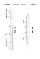
- FIG. 1A is a diametrical sectional view through a gel drumhead according to the invention.
- FIG. 1B is a diametrical sectional view through a gel drumhead according to the invention having the gel encapsulated in a pouch;
- FIG. 2 is a diagrammatical diametrical sectional view of a conventional drumhead illustrating a typical range of deflection when struck;
- FIG. 3 is a diagrammatical representation of a suitable piezoelectric transducer for attachment to the underside of the gel pad drumhead;
- FIG. 4 is an exploded view of a piezoelectric transducer assembly suitable for use in the invention.
- FIG. 5 is a diagrammatical diametrical sectional view showing the assembly of FIG. 4 mechanically coupled to the gel drumhead according to the invention
- FIG. 6 is a diagrammatical diametrical sectional view of another embodiment using a piezoelectric film sandwiched between the gel drumhead and the solid plate;
- FIG. 7 is another alternative embodiment of the invention showing an exploded view of a force sensing resistor sandwiched between the gel drumhead and the solid plate;
- FIG. 8A is a perspective view of another embodiment of the invention suitable for use as an electronic bass drum
- FIG. 8B is a front view of the back plate of FIG. 8A.
- FIG. 9 is an exploded diagrammatic elevation view of another embodiment of the invention using a voice coil transducer.
- a gel is a two-phase colloidal system consisting of a solid and a liquid in more solid form than a sol, a sol being a colloidal solution consisting of a suitable dispersion medium, which may be gas, liquid, or solid and the colloidal substance, the disperse phase, which is distributed throughout the dispersion medium.
- the gel 12 typically comprises a base material, such as Kraton, polyurethane, PVC (polyvinyl chloride) and silicon.
- the gel 12 may have a durometer range of 5 shore-00 to 80 shore-00.
- the 00 scale is a standard scale for measuring some foams and very soft substrates.
- the Kraton gel 12 is a styrene, oil and rubber based gel commercially available from Shell Oil Company sold under the trademark Kraton.
- FIG. 1B there is shown a diametrical sectional view of a drumhead 11' with a gel 12' encapsulated in a pouch 13' typically made of urethane.
- Gel 12' maybe PVC, polyurethane or silicone.
- the polyurethane pouch 13' is typically 60 durometer shore-A which provides a nonstick barrier for shore 00 compounds of polyurethane, PVC and silicone.
- the Kraton gel 12 is especially advantageous for drumheads because it may be pelletized and injection-molded. For a bass drum pad (FIGS. 8A and 8B) polyurethane gel has been advantageously used.
- the shore 00 durometers selected for the gel is preferably related to the acoustical drum being simulated by a gel-headed electronic drum according to the invention. It is preferred that the give or throw of the gel drumhead and the restoring force that returns the gel drumhead surface to its rest position correspond to that of the acoustic drum being simulated.
- the gel drumhead is preferably thick enough to absorb enough energy from the stick, mallet or beater before the average drummer will exceed the damping properties of the gel which would occur when the gel compresses at the point of impact to where the top surface is substantially in contact with the bottom surface of the gel and is preferably at least 0.250 inch thick.
- FIG. 2 there is shown a diagrammatic representation of conventional drumhead 11" in its rest position and in the flex position 11'" after being struck.
- FIG. 3 there is shown a diagrammatic elevation view of a piezoelectric transducer structure including a ceramic crystal 14 attached to a metal disc 15 that furnishes a transduced signal between leads 16.
- the resonant characteristics of the device are related to the diameter and thickness of disc 15.
- the voltage output is proportional to the thickness of the ceramic crystal 14 and the magnitude of the force applied to the assembly.
- the assembly used in the invention preferably has a resonant frequency below 1500 Hz.
- FIG. 4 there is shown an exploded diagrammatic representation in elevation of a suitable piezoelectric assembly for use in the invention.
- Metal disc 15 is attached to a solid plate 16 by an annular spacer gasket 17 and carries a weight 18 attached to the center of disc 15.
- FIG. 5 there is shown a diagrammatical representation in elevation of the assembly of FIG. 4 mechanically coupled to gel head 11 through a polyester film 21 attached to solid plate 16.
- Polyester film 21 is formed with an annular convolution 21A embracing solid plate 16.
- the resonant frequency of the assembly is reduced to a value near that of the natural frequency of gel head 11 and the driving force frequency, both of which are typically below 100 Hz. Because the spring mass system of FIG. 6 is more a shock sensor than a strain sensor, the output signal is more nearly uniform with respect to the striking position on the gel drumhead surface; that is, edge-vs.-center.
- the spring mass resonant frequency is related to the thickness of gel head 11 and plate 16. Increasing thickness of plate 16 is preferably accompanied by an increase in the mass of the assembly suspended from spacer gasket 17 to increase sensitivity by correspondingly lowering the resonance of the assembly attached to plate 16. A resonance of 160 Hz has been found to be especially advantageous.
- Polyester suspension film 21 helps provide a suspension system independent of the suspension of ceramic disc 14 and provides a barrier to outside vibration. Varying the thickness of polyester film 21 and the radius of convolution 21A affects the rebound of the stick striking gel head 11. As a result, a combination of the durometer of gel 12 and these properties of polyester film 21 allows achieving the throw and rebound of the various tunings of an acoustic drum being simulated.
- MIDI musical instrument digital interface
- FIG. 6 there is shown a diagrammatic representation in elevation of another embodiment of the invention having a piezoelectric film 22 sandwiched between the gel drumhead 11 and a solid plate 16'.
- FIG. 7 there is shown a diagrammatic exploded view in elevation of another embodiment of the invention with a force-sensing resistor 23 sandwiched between gel drumhead 11 and solid plate 16'.
- FIG. 8A there is shown a perspective view of an electronic bass drum comprising a back plate 31 attached to the top of vertical arms 32 and 33 pivotally attached at the bottom to an axle 34 supported in the rear ends of horizontal arms 35 and 36 attached at their front ends to front horizontal bar 37.
- Stay arms 41 and 42 are pivotally attached at their top to the middle of vertical arms 32 and 33, respectively and at their bottom ends to studs, such as 43 so that the unit can collapse downward for transport.
- Backplate 31 carries a piezoelectric transducer 44.
- FIG. 8B there is shown a front view of backplate 31 having gel 11" secured by retaining ring 45.
- FIG. 9 there is shown a diagrammatic exploded view in elevation of another embodiment of the invention using a loudspeaker transducing assembly.
- Gel head 11 is attached to mylar head 51 formed with an annular convolution 51A embracing a stiffening plate 52.
- Driver assembly 53 is attached to stiffening plate 52 and includes a spider 53A supporting a voice coil 53B free to move in the gap 53C of the permanent magnet structure 53D that creates a magnetic field in gap 53C.
- a mounting screw 54 passing through spacer 55 secures driver assembly 53 to shell 56 that carries a connector 57 connected by leads 58 to voice coil 53B.
- the drumhead convolution 51A and spider 53A are preferably constructed and arranged so that a maximum of 70 milliseconds decay time is reached with no peaks greater than 50% of the original peak when observing the output signal furnished by connector 57 on an oscilloscope.
- the system resonant frequency is preferably above 50 Hz. Controlling the resonant frequency of the system helps avoid confusing the threshold of the input comparator of a MIDI computer by multiple oscillations caused by ringing of the mass-spring system.
- stiffening plate 52 have a flex modulus of at least 200,000 psi to achieve good transmission from gel drumhead 11 to the transducer.
- the system suspension is preferably tuned closer to a midrange loudspeaker, with the dimensions closer to those of a woofer, a typical diameter of gel drumhead 11 being 10 inches.
Landscapes
- Physics & Mathematics (AREA)
- Engineering & Computer Science (AREA)
- Acoustics & Sound (AREA)
- Multimedia (AREA)
- Piezo-Electric Transducers For Audible Bands (AREA)
Abstract
Description
Claims (8)
Priority Applications (2)
| Application Number | Priority Date | Filing Date | Title |
|---|---|---|---|
| US08/584,316 US5585581A (en) | 1992-06-23 | 1996-01-16 | Gel drumhead transducing |
| JP9005891A JPH09311684A (en) | 1996-01-16 | 1997-01-16 | Gel drumhead transducer |
Applications Claiming Priority (2)
| Application Number | Priority Date | Filing Date | Title |
|---|---|---|---|
| US07/902,715 US5637819A (en) | 1992-06-23 | 1992-06-23 | Percussion instrument damping |
| US08/584,316 US5585581A (en) | 1992-06-23 | 1996-01-16 | Gel drumhead transducing |
Related Parent Applications (1)
| Application Number | Title | Priority Date | Filing Date |
|---|---|---|---|
| US07/902,715 Continuation-In-Part US5637819A (en) | 1992-06-23 | 1992-06-23 | Percussion instrument damping |
Publications (1)
| Publication Number | Publication Date |
|---|---|
| US5585581A true US5585581A (en) | 1996-12-17 |
Family
ID=46202836
Family Applications (1)
| Application Number | Title | Priority Date | Filing Date |
|---|---|---|---|
| US08/584,316 Expired - Fee Related US5585581A (en) | 1992-06-23 | 1996-01-16 | Gel drumhead transducing |
Country Status (1)
| Country | Link |
|---|---|
| US (1) | US5585581A (en) |
Cited By (26)
| Publication number | Priority date | Publication date | Assignee | Title |
|---|---|---|---|---|
| US5920026A (en) * | 1996-07-04 | 1999-07-06 | Roland Kabsuhiki Kaisha | Electronic percussion instrument with a net-like material to minimize noise |
| US6271458B1 (en) | 1996-07-04 | 2001-08-07 | Roland Kabushiki Kaisha | Electronic percussion instrumental system and percussion detecting apparatus therein |
| US20040083873A1 (en) * | 1996-07-04 | 2004-05-06 | Roland Kabushiki Kaisha | Electronic percussion instrumental system and percussion detecting apparatus therein |
| US20040118269A1 (en) * | 2002-12-17 | 2004-06-24 | Roland Corporation | Electronic percussion instrument and vibration detection apparatus |
| US6762353B2 (en) * | 2002-01-18 | 2004-07-13 | Yamaha Corporation | Percussion instrument head |
| US20040134332A1 (en) * | 2003-01-14 | 2004-07-15 | Roland Corporation | Acoustic instrument triggering device and method |
| US20040211310A1 (en) * | 2003-04-25 | 2004-10-28 | Takashi Hagiwara | Sound pickup device for percussion instrument |
| US20050211062A1 (en) * | 2004-03-08 | 2005-09-29 | Yamaha Corporation | Pad for electronic drum and electronic drum |
| US20050281634A1 (en) * | 2004-06-18 | 2005-12-22 | Patricia Tibbenham | Waffle stud for insert molded plastic members |
| US20060230912A1 (en) * | 2005-04-13 | 2006-10-19 | Pickens Keith A | Hybrid electric/acoustic percussion instrument |
| US20060283311A1 (en) * | 2002-02-26 | 2006-12-21 | Hosler David L | Transducer for converting between mechanical vibration and electrical signal |
| US20070017345A1 (en) * | 2005-07-25 | 2007-01-25 | Russell Stoneback | Electromagnetic musical instruments |
| US20070017344A1 (en) * | 2005-07-25 | 2007-01-25 | Russell Stoneback | Electromagnetic musical instrument systems and related methods |
| US20070137460A1 (en) * | 2005-12-19 | 2007-06-21 | Korg Inc. | Percussion-instrument pickup and electric percussion instrument |
| US20080156169A1 (en) * | 2007-01-03 | 2008-07-03 | Twu Hwei-Ming | Viola/Violin Shoulder Rest |
| US7985908B1 (en) * | 2008-07-25 | 2011-07-26 | Offworld Percussion | Practice drum pad assembly and rim therefor |
| US20130098227A1 (en) * | 2011-10-20 | 2013-04-25 | Guo-Hsiung Wei | Detachable electronic drum |
| US20140069265A1 (en) * | 2012-09-12 | 2014-03-13 | Ai-Musics Technology Inc. | Electric Drum And Cymbal With Spider Web-Like Sensor |
| US20140216234A1 (en) * | 2012-07-05 | 2014-08-07 | Ai-Musics Technology Inc. | Detachable Electronic Drum |
| US20140260920A1 (en) * | 2013-03-12 | 2014-09-18 | Yamaha Corporation | Electronic percussion instrument |
| US9053694B2 (en) | 2013-03-12 | 2015-06-09 | Yamaha Corporation | Electronic percussion instrument |
| US9142202B2 (en) * | 2013-08-20 | 2015-09-22 | Yamaha Corporation | Electronic percussion pad and method of manufacturing electronic percussion pad |
| US9153220B2 (en) | 2013-03-12 | 2015-10-06 | Yamaha Corporation | Electronic percussion instrument |
| US9196237B2 (en) | 2013-03-12 | 2015-11-24 | Yamaha Corporation | Electronic percussion instrument |
| US20160140945A1 (en) * | 2013-06-21 | 2016-05-19 | Parsek Lab S.R.L. | Electronic Musical Instrument Percussion System with Electromagnetic Sensor |
| US9460699B2 (en) | 2013-03-12 | 2016-10-04 | Yamaha Corporation | Electronic percussion instrument |
Citations (3)
| Publication number | Priority date | Publication date | Assignee | Title |
|---|---|---|---|---|
| US4282793A (en) * | 1978-05-30 | 1981-08-11 | Research Development Systems, Inc. | Composite drum head |
| US5385076A (en) * | 1994-06-20 | 1995-01-31 | Remo, Inc. | Reinforced drumhead |
| US5430245A (en) * | 1993-01-14 | 1995-07-04 | Rtom Corporation | Electroacoustical drum |
-
1996
- 1996-01-16 US US08/584,316 patent/US5585581A/en not_active Expired - Fee Related
Patent Citations (3)
| Publication number | Priority date | Publication date | Assignee | Title |
|---|---|---|---|---|
| US4282793A (en) * | 1978-05-30 | 1981-08-11 | Research Development Systems, Inc. | Composite drum head |
| US5430245A (en) * | 1993-01-14 | 1995-07-04 | Rtom Corporation | Electroacoustical drum |
| US5385076A (en) * | 1994-06-20 | 1995-01-31 | Remo, Inc. | Reinforced drumhead |
Cited By (50)
| Publication number | Priority date | Publication date | Assignee | Title |
|---|---|---|---|---|
| US5920026A (en) * | 1996-07-04 | 1999-07-06 | Roland Kabsuhiki Kaisha | Electronic percussion instrument with a net-like material to minimize noise |
| US6121538A (en) * | 1996-07-04 | 2000-09-19 | Roland Corporation | Electronic percussion instrumental system and percussion detecting apparatus therein |
| US6271458B1 (en) | 1996-07-04 | 2001-08-07 | Roland Kabushiki Kaisha | Electronic percussion instrumental system and percussion detecting apparatus therein |
| US20040083873A1 (en) * | 1996-07-04 | 2004-05-06 | Roland Kabushiki Kaisha | Electronic percussion instrumental system and percussion detecting apparatus therein |
| US6756535B1 (en) | 1996-07-04 | 2004-06-29 | Roland Corporation | Electronic percussion instrumental system and percussion detecting apparatus therein |
| US7385135B2 (en) | 1996-07-04 | 2008-06-10 | Roland Corporation | Electronic percussion instrumental system and percussion detecting apparatus therein |
| US20050223880A1 (en) * | 1996-07-04 | 2005-10-13 | Kiyoshi Yoshino | Electronic percussion instrumental system and percussion detecting apparatus therein |
| US6921857B2 (en) | 1996-07-04 | 2005-07-26 | Roland Corporation | Electronic percussion instrumental system and percussion detecting apparatus therein |
| US6762353B2 (en) * | 2002-01-18 | 2004-07-13 | Yamaha Corporation | Percussion instrument head |
| US20060283311A1 (en) * | 2002-02-26 | 2006-12-21 | Hosler David L | Transducer for converting between mechanical vibration and electrical signal |
| US7667128B2 (en) * | 2002-02-26 | 2010-02-23 | Taylor-Listug, Inc. | Transducer for converting between mechanical vibration and electrical signal |
| US20040118269A1 (en) * | 2002-12-17 | 2004-06-24 | Roland Corporation | Electronic percussion instrument and vibration detection apparatus |
| US7038117B2 (en) | 2002-12-17 | 2006-05-02 | Roland Corporation | Electronic percussion instrument and vibration detection apparatus |
| US6794569B2 (en) | 2003-01-14 | 2004-09-21 | Roland Corporation | Acoustic instrument triggering device and method |
| US20040134332A1 (en) * | 2003-01-14 | 2004-07-15 | Roland Corporation | Acoustic instrument triggering device and method |
| US20040211310A1 (en) * | 2003-04-25 | 2004-10-28 | Takashi Hagiwara | Sound pickup device for percussion instrument |
| US7256342B2 (en) * | 2003-04-25 | 2007-08-14 | Yamaha Corporation | Sound pickup device for percussion instrument |
| US20050211062A1 (en) * | 2004-03-08 | 2005-09-29 | Yamaha Corporation | Pad for electronic drum and electronic drum |
| US7439432B2 (en) * | 2004-03-08 | 2008-10-21 | Yamaha Corporation | Pad for electronic drum and electronic drum |
| US20050281634A1 (en) * | 2004-06-18 | 2005-12-22 | Patricia Tibbenham | Waffle stud for insert molded plastic members |
| US7156598B2 (en) * | 2004-06-18 | 2007-01-02 | Ford Global Technologies, Llc | Waffle stud for insert molded plastic members |
| US20060230912A1 (en) * | 2005-04-13 | 2006-10-19 | Pickens Keith A | Hybrid electric/acoustic percussion instrument |
| US7179985B2 (en) * | 2005-04-13 | 2007-02-20 | Kieffa Drums, Llc | Hybrid electric/acoustic percussion instrument |
| US20070169610A1 (en) * | 2005-04-13 | 2007-07-26 | Pickens Keith A | Acoustic practice percussion instrument and practice kit |
| US7429698B2 (en) * | 2005-04-13 | 2008-09-30 | Kieffa Drums, Llc | Acoustic practice percussion instrument and practice kit |
| US20070214940A1 (en) * | 2005-07-25 | 2007-09-20 | Russell Stoneback | Electromagnetic musical instrument frequency conversion systems and related methods |
| US20070017345A1 (en) * | 2005-07-25 | 2007-01-25 | Russell Stoneback | Electromagnetic musical instruments |
| US7777119B2 (en) * | 2005-07-25 | 2010-08-17 | Russell Stoneback | Electromagnetic musical instruments |
| US7777120B2 (en) * | 2005-07-25 | 2010-08-17 | Russell Stoneback | Electromagnetic musical instrument frequency conversion systems and related methods |
| US20070017344A1 (en) * | 2005-07-25 | 2007-01-25 | Russell Stoneback | Electromagnetic musical instrument systems and related methods |
| US7777118B2 (en) * | 2005-07-25 | 2010-08-17 | Russell Stoneback | Electromagnetic musical instrument systems and related methods |
| US20070137460A1 (en) * | 2005-12-19 | 2007-06-21 | Korg Inc. | Percussion-instrument pickup and electric percussion instrument |
| US7488887B2 (en) * | 2005-12-19 | 2009-02-10 | Korg Inc. | Percussion-instrument pickup and electric percussion instrument |
| US20080156169A1 (en) * | 2007-01-03 | 2008-07-03 | Twu Hwei-Ming | Viola/Violin Shoulder Rest |
| US7659463B2 (en) * | 2007-01-03 | 2010-02-09 | Twu Hwei-Ming | Viola/violin shoulder rest |
| US7985908B1 (en) * | 2008-07-25 | 2011-07-26 | Offworld Percussion | Practice drum pad assembly and rim therefor |
| US20130098227A1 (en) * | 2011-10-20 | 2013-04-25 | Guo-Hsiung Wei | Detachable electronic drum |
| US8841538B2 (en) * | 2011-10-20 | 2014-09-23 | Ai-Musics Technology Inc. | Detachable electronic drum |
| US20140216234A1 (en) * | 2012-07-05 | 2014-08-07 | Ai-Musics Technology Inc. | Detachable Electronic Drum |
| US9202451B2 (en) * | 2012-07-05 | 2015-12-01 | Ai-Musics Technology Inc. | Detachable electronic drum |
| US20140069265A1 (en) * | 2012-09-12 | 2014-03-13 | Ai-Musics Technology Inc. | Electric Drum And Cymbal With Spider Web-Like Sensor |
| US8841527B2 (en) * | 2012-09-12 | 2014-09-23 | Al-Musics Technology Inc. | Electric drum and cymbal with spider web-like sensor |
| US9053694B2 (en) | 2013-03-12 | 2015-06-09 | Yamaha Corporation | Electronic percussion instrument |
| US9129585B2 (en) * | 2013-03-12 | 2015-09-08 | Yamaha Corporation | Electronic percussion instrument |
| US9153220B2 (en) | 2013-03-12 | 2015-10-06 | Yamaha Corporation | Electronic percussion instrument |
| US9196237B2 (en) | 2013-03-12 | 2015-11-24 | Yamaha Corporation | Electronic percussion instrument |
| US20140260920A1 (en) * | 2013-03-12 | 2014-09-18 | Yamaha Corporation | Electronic percussion instrument |
| US9460699B2 (en) | 2013-03-12 | 2016-10-04 | Yamaha Corporation | Electronic percussion instrument |
| US20160140945A1 (en) * | 2013-06-21 | 2016-05-19 | Parsek Lab S.R.L. | Electronic Musical Instrument Percussion System with Electromagnetic Sensor |
| US9142202B2 (en) * | 2013-08-20 | 2015-09-22 | Yamaha Corporation | Electronic percussion pad and method of manufacturing electronic percussion pad |
Similar Documents
| Publication | Publication Date | Title |
|---|---|---|
| US5585581A (en) | Gel drumhead transducing | |
| JP3818203B2 (en) | Electronic percussion instrument | |
| US9761212B2 (en) | Magnetically secured instrument trigger | |
| US4567805A (en) | Compliant bridge transducer for rigid body string musical instruments | |
| US10096309B2 (en) | Magnetically secured instrument trigger | |
| JP3484143B2 (en) | Speaker device | |
| US5430245A (en) | Electroacoustical drum | |
| US5123326A (en) | String musical instrument with tone engendering structures | |
| US4750397A (en) | Electronic musical instrument with elastomeric strings and shielded bimorphic transducers | |
| GB2166022A (en) | Piezoelectric vibrator | |
| US3733425A (en) | Pick up device for stringed instrument | |
| JP3192100B2 (en) | Microphone | |
| US20050039593A1 (en) | Percussion transducer | |
| JPH04502215A (en) | Conversion device for musical instruments | |
| US5396024A (en) | Electric percussion instrument equipped with vibration sensor supported by retainer of vibration-transmissive substance | |
| GB2196462A (en) | Electronic drum | |
| JPH09244633A (en) | Electronic drum pad | |
| CN106560890B (en) | Vibration isolation pickup unit for stringed instrument | |
| WO2016005729A2 (en) | Electronic percussion instruments and triggers | |
| US3311712A (en) | Sonic transducer | |
| JP3434509B2 (en) | Analog electronic drum set, parts for analog electronic drum set, raw drum set, sound collecting method for raw drum set, sound collecting method for drum system parts of raw drum set, sound collecting method for cymbal of raw drum set, and raw drum set Sound collection method for hi-hat cymbals | |
| US2703343A (en) | Phonograph pickup | |
| JPH09311684A (en) | Gel drumhead transducer | |
| Omata | New type transducer for measuring contact compliances of a soft body | |
| US5552562A (en) | Inertial acoustic pickup |
Legal Events
| Date | Code | Title | Description |
|---|---|---|---|
| AS | Assignment |
Owner name: RTOM CORPORATION, A NEW JERSEY CORPORATION, NEW JE Free format text: ASSIGNMENT OF ASSIGNORS INTEREST;ASSIGNOR:ROGERS, THOMAS P.;REEL/FRAME:007861/0729 Effective date: 19960304 |
|
| AS | Assignment |
Owner name: ALESIS CORPORATION, CALIFORNIA Free format text: SECURITY AGREEMENT;ASSIGNOR:RTOM CORPORATION;REEL/FRAME:008933/0909 Effective date: 19971015 |
|
| FPAY | Fee payment |
Year of fee payment: 4 |
|
| REMI | Maintenance fee reminder mailed | ||
| LAPS | Lapse for failure to pay maintenance fees | ||
| STCH | Information on status: patent discontinuation |
Free format text: PATENT EXPIRED DUE TO NONPAYMENT OF MAINTENANCE FEES UNDER 37 CFR 1.362 |
|
| FP | Expired due to failure to pay maintenance fee |
Effective date: 20041217 |