US5575624A - Metal contoured blade for a reversible ceiling fan - Google Patents
Metal contoured blade for a reversible ceiling fan Download PDFInfo
- Publication number
- US5575624A US5575624A US08/601,396 US60139696A US5575624A US 5575624 A US5575624 A US 5575624A US 60139696 A US60139696 A US 60139696A US 5575624 A US5575624 A US 5575624A
- Authority
- US
- United States
- Prior art keywords
- fan
- blade
- ceiling
- edge
- metal
- Prior art date
- Legal status (The legal status is an assumption and is not a legal conclusion. Google has not performed a legal analysis and makes no representation as to the accuracy of the status listed.)
- Expired - Lifetime
Links
Images
Classifications
-
- F—MECHANICAL ENGINEERING; LIGHTING; HEATING; WEAPONS; BLASTING
- F04—POSITIVE - DISPLACEMENT MACHINES FOR LIQUIDS; PUMPS FOR LIQUIDS OR ELASTIC FLUIDS
- F04D—NON-POSITIVE-DISPLACEMENT PUMPS
- F04D29/00—Details, component parts, or accessories
- F04D29/26—Rotors specially for elastic fluids
- F04D29/32—Rotors specially for elastic fluids for axial flow pumps
- F04D29/38—Blades
- F04D29/384—Blades characterised by form
Definitions
- the present invention is directed to ceiling fans and in particular to a ceiling fan manufactured with metal contoured blades for controlling the direction of the air flow.
- 4,892,460 discloses a ceiling fan having a fan blade 2 with a trailing edge to which an auxiliary blade 1 is attached; note that the auxiliary blade 1 is merely arcuate and is not contoured like applicant's invention and that this patented fan would not operate in the reverse direction, that the blade 24 is twisted at its free end 27, and that such blade does not utilize a constant contour as used by applicant.
- U.S. Pat. No. 3,174,681 discloses a reversible propeller wherein each blade has an S-shaped cross section which is not constant but rather varies from the central hub to the tip thereof.
- U.S. Pat. No. 2,609,055 shows a reversible propeller blade having opposite sides which are not S-shaped and which are constructed by two separate sections that are joined together.
- U.S. Pat. No. 1,506,937 relates to a fan blade which is twisted along its longitudinal axis and which has a contour that is not constant but rather varies along such axis.
- the present invention is summarized in the combination of a reversible ceiling fan and a contoured unitary blade, which fan is adapted to be secured to a ceiling or the like; wherein each blade is metal and has contoured upper and lower surfaces defining an S-shaped configuration for selectively directing the air flow from the blade upward or downward in accordance with the direction of rotation of the blade.
- An object of the present invention is to simplify the construction of a reversible ceiling fan by means of a contoured metal blade to direct air flow according to the direction of rotation of the fan.
- This invention has another object in that a reversible ceiling fan is mounted adjacent to the ceiling which may be utilized to facilitate changing the upward direction of the air flow to a generally downward direction.
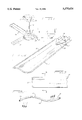
- FIG. 1 is a perspective view of an overhead fan suspended from a ceiling and constructed in accordance with the present invention
- FIG. 2 is a perspective view of a contoured metal fan blade shown in FIG. 1;
- FIG. 3 is a top plan view of a portion of the blade in FIG. 2;
- FIG. 4 is a cross sectional view taken along line 4--4 in FIG. 3.
- a ceiling fan includes an upper supporting portion 10 secured to a ceiling C by any suitable means (not shown) and a support shaft 12 leading to a lower housing 14 for a conventional electric reversible motor.
- a plurality of spaced fan blades 16 (three in this instance) are fixed at their inner end to the housing 14 for rotation therewith by means of a mounting plate 18.
- Two cap bolts (not shown) fasten the plate 18 to the rim of housing 14 while three cap bolts 22 fasten the plate 18 along with three bushings (not shown) to the end portion of blade 16 which is provided with three matching holes 23 (FIG. 2).
- the metal blade 16 is S-shaped in width with the middle of the S defining the longitudinal axis of the blade. As is apparent in FIG. 2, the S-shape presents a contour for the metal blade 16 which is constant for the length of the longitudinal axis of the blade.
- the width of the blade 16 shows the S-shape to be a flattened curve or an opened ended S.
- a control switch may take the form of a 3-way switch having a first off position, a second on position for clockwise rotation and a third on position for counterwise position.
- Operation of the contoured fan is accomplished by moving the switch from the first off position to the second on position whereby the fan is rotated in a clockwise direction and the air is moved in a generally upwardly direction (FIG. 4) as would be helpful in large greenhouses and/or poultry farmhouses.
- Wintertime operation of the contoured fan is effected by moving the switch to the third on position whereby the fan is rotated in a counterclockwise direction and the air is moved generally downwardly (FIG. 4) as would be helpful to exhaust the air through open windows; by closing the windows the air would be diverted from the ceiling downwardly toward the floor.
- the construction utilizes the ceiling for redirecting the air flow; this simple arrangement removes the expensive and cumbersome features of the prior art devices.
- a residential style fan is mounted in an 8 foot ceiling and uses a flat wooden paddle blade that operates in either direction with minimal air flow.
- a commercial and industrial fan operates in spacious areas with ceiling heights from 12 to 80 feet and requires a contour blade and a large motor to achieve maximum performance.
- a standard metal contoured blade achieves air flow in a clockwise rotation but at the same time the back of the blade rolls the air off in the clockwise direction.
- the metal blade of the present invention overcomes the above problems in that one-half is designed for forward operation while the other half free wheels. When this rotation is reversed, the free wheel is on the opposite side, thus producing opposite air delivery with minimal drag or resistance.
- This new blade serves as a dual purpose product. In effect, instead of manually changing the blade set to up side down for reverse operations, the new blade is two blades in one. It is virtually impossible to change blades when the mounting heights of the fans are 12 to 85 feet in the air. With the new blade, the feature of reversing the air flow is achieved without changing the blade set.
- ceiling fans are installed in rooms having ceilings of approximately 8 feet in height.
- the current safety standard permits ceiling fans to be suspended in applications where the height from blade to floor exceeds 7 feet provided the blade thickness is a minimum of 3/16 inch at the forward impact edge.
- Such safety standard was set upon the thickness of wooden paddle fan blades and virtually eliminated the use of metal blades.
- the present invention solves the above problem by designing the edge of the metal blade to duplicate the edge of the wooden paddle, i.e., 3/16 inch.
- the three outer edges of the contoured metal blade 16 are each rolled back to form a 3/16 inch roll. It is recognized that a contoured aerodynamic metal blade has superior air velocity compared to a flat wooden blade design. This unique rolled edge metal blade design permits the metal high velocity blade to be used in low ceiling areas that heretofore were precluded for metal blades.
- the reversing contoured metal blade 16 includes a continuous rolled edge 17 defined by the leading and trailing edges and the end shape therebetween.
- the trailing edge 3/16 inch piece of metal acts as an air brake which increases the drag on the motor and causes the temperature heat rise of the motor.
- the back side of the rolled edge 17 is shown in FIG. 4 as being filled with filler putty 19 whereby the drag is eliminated.
Landscapes
- Engineering & Computer Science (AREA)
- Mechanical Engineering (AREA)
- General Engineering & Computer Science (AREA)
- Structures Of Non-Positive Displacement Pumps (AREA)
Abstract
Description
Claims (3)
Priority Applications (3)
| Application Number | Priority Date | Filing Date | Title |
|---|---|---|---|
| US08/601,396 US5575624A (en) | 1996-02-14 | 1996-02-14 | Metal contoured blade for a reversible ceiling fan |
| PCT/US1997/001413 WO1997030290A1 (en) | 1996-02-14 | 1997-02-07 | Metal contoured blade for a reversible ceiling fan |
| AU18607/97A AU1860797A (en) | 1996-02-14 | 1997-02-07 | Metal contoured blade for a reversible ceiling fan |
Applications Claiming Priority (1)
| Application Number | Priority Date | Filing Date | Title |
|---|---|---|---|
| US08/601,396 US5575624A (en) | 1996-02-14 | 1996-02-14 | Metal contoured blade for a reversible ceiling fan |
Publications (1)
| Publication Number | Publication Date |
|---|---|
| US5575624A true US5575624A (en) | 1996-11-19 |
Family
ID=24407326
Family Applications (1)
| Application Number | Title | Priority Date | Filing Date |
|---|---|---|---|
| US08/601,396 Expired - Lifetime US5575624A (en) | 1996-02-14 | 1996-02-14 | Metal contoured blade for a reversible ceiling fan |
Country Status (3)
| Country | Link |
|---|---|
| US (1) | US5575624A (en) |
| AU (1) | AU1860797A (en) |
| WO (1) | WO1997030290A1 (en) |
Cited By (28)
| Publication number | Priority date | Publication date | Assignee | Title |
|---|---|---|---|---|
| US6164919A (en) * | 1997-12-12 | 2000-12-26 | Vanmoor; Arthur | Propeller and impeller blade configuration |
| US20040156716A1 (en) * | 2003-02-12 | 2004-08-12 | Samsung Electronics Co., Ltd. | Air circulating device |
| US20050129523A1 (en) * | 2003-12-11 | 2005-06-16 | Liu Ching Wen W. | Ceiling fan blade |
| US20070104582A1 (en) * | 2005-11-04 | 2007-05-10 | Rahai Hamid R | Vertical axis wind turbine with optimized blade profile |
| US20080069700A1 (en) * | 2006-09-14 | 2008-03-20 | Karun Laisathit | Reversible Fan Blade For a Ceiling-Suspended Fan |
| US20090324416A1 (en) * | 2008-06-30 | 2009-12-31 | Ge Wind Energy Gmbh | Wind turbine blades with multiple curvatures |
| US8807938B2 (en) | 2005-07-13 | 2014-08-19 | Beacon Lighting International Limited | Combined light fitting and ceiling fan |
| CN104747497A (en) * | 2013-12-27 | 2015-07-01 | 广东美的环境电器制造有限公司 | Fan blade and fan with same |
| USD761949S1 (en) * | 2015-01-12 | 2016-07-19 | Hunter Fan Company | Ceiling fan |
| USD861153S1 (en) | 2018-06-05 | 2019-09-24 | Chia-Teh Chen | Ceiling fan with light |
| USD880682S1 (en) | 2018-07-10 | 2020-04-07 | Hunter Fan Company | Ceiling fan blade |
| USD880684S1 (en) | 2018-07-10 | 2020-04-07 | Hunter Fan Company | Ceiling fan blade |
| USD880680S1 (en) | 2018-07-10 | 2020-04-07 | Hunter Fan Company | Ceiling fan blade |
| USD880681S1 (en) | 2018-07-10 | 2020-04-07 | Hunter Fan Company | Ceiling fan blade |
| USD880683S1 (en) | 2018-07-10 | 2020-04-07 | Hunter Fan Company | Ceiling fan blade |
| USD902377S1 (en) | 2018-07-10 | 2020-11-17 | Hunter Fan Company | Ceiling fan blade |
| USD903091S1 (en) | 2018-07-10 | 2020-11-24 | Hunter Fan Company | Ceiling fan blade |
| USD903092S1 (en) | 2018-07-10 | 2020-11-24 | Hunter Fan Company | Ceiling fan blade |
| USD905226S1 (en) | 2018-07-10 | 2020-12-15 | Hunter Fan Company | Ceiling fan blade |
| USD905227S1 (en) | 2018-07-10 | 2020-12-15 | Hunter Fan Company | Ceiling fan blade |
| USD905845S1 (en) | 2018-07-10 | 2020-12-22 | Hunter Fan Company | Ceiling fan blade |
| USD906511S1 (en) | 2018-07-10 | 2020-12-29 | Hunter Fan Company | Ceiling fan blade |
| US11111930B2 (en) | 2018-07-10 | 2021-09-07 | Hunter Fan Company | Ceiling fan blade |
| US11193502B2 (en) | 2015-12-14 | 2021-12-07 | Hunter Fan Company | Ceiling fan |
| USD957619S1 (en) | 2018-07-10 | 2022-07-12 | Hunter Fan Company | Ceiling fan blade |
| USD957617S1 (en) | 2018-07-10 | 2022-07-12 | Hunter Fan Company | Ceiling fan blade |
| USD957618S1 (en) | 2018-07-10 | 2022-07-12 | Hunter Fan Compnay | Ceiling fan blade |
| USD980408S1 (en) | 2018-07-10 | 2023-03-07 | Hunter Fan Company | Ceiling fan blade |
Citations (9)
| Publication number | Priority date | Publication date | Assignee | Title |
|---|---|---|---|---|
| US1473066A (en) * | 1922-03-20 | 1923-11-06 | Merritt R Wells | Fan for automobile radiators or the like |
| US1506937A (en) * | 1923-03-09 | 1924-09-02 | Tom Moore | Blade |
| US1597175A (en) * | 1925-03-17 | 1926-08-24 | Boening Ernest | Propeller |
| US1628716A (en) * | 1925-08-28 | 1927-05-17 | Fischer Joseph | Aerial propeller |
| US1818607A (en) * | 1928-08-27 | 1931-08-11 | Chrysler Corp | Fan |
| US2175609A (en) * | 1938-01-29 | 1939-10-10 | Leeb Frank | Airplane propeller blade |
| US2609055A (en) * | 1949-11-08 | 1952-09-02 | Hartzell Propeller Fan Company | Reversible propeller blade |
| US3174681A (en) * | 1963-02-27 | 1965-03-23 | Aerovent Fan Company Inc | Reversible propeller |
| US4892460A (en) * | 1989-01-30 | 1990-01-09 | Volk Steve J | Propeller breeze enhancing blades for conventional ceiling fans |
-
1996
- 1996-02-14 US US08/601,396 patent/US5575624A/en not_active Expired - Lifetime
-
1997
- 1997-02-07 AU AU18607/97A patent/AU1860797A/en not_active Abandoned
- 1997-02-07 WO PCT/US1997/001413 patent/WO1997030290A1/en active Application Filing
Patent Citations (9)
| Publication number | Priority date | Publication date | Assignee | Title |
|---|---|---|---|---|
| US1473066A (en) * | 1922-03-20 | 1923-11-06 | Merritt R Wells | Fan for automobile radiators or the like |
| US1506937A (en) * | 1923-03-09 | 1924-09-02 | Tom Moore | Blade |
| US1597175A (en) * | 1925-03-17 | 1926-08-24 | Boening Ernest | Propeller |
| US1628716A (en) * | 1925-08-28 | 1927-05-17 | Fischer Joseph | Aerial propeller |
| US1818607A (en) * | 1928-08-27 | 1931-08-11 | Chrysler Corp | Fan |
| US2175609A (en) * | 1938-01-29 | 1939-10-10 | Leeb Frank | Airplane propeller blade |
| US2609055A (en) * | 1949-11-08 | 1952-09-02 | Hartzell Propeller Fan Company | Reversible propeller blade |
| US3174681A (en) * | 1963-02-27 | 1965-03-23 | Aerovent Fan Company Inc | Reversible propeller |
| US4892460A (en) * | 1989-01-30 | 1990-01-09 | Volk Steve J | Propeller breeze enhancing blades for conventional ceiling fans |
Cited By (42)
| Publication number | Priority date | Publication date | Assignee | Title |
|---|---|---|---|---|
| US6164919A (en) * | 1997-12-12 | 2000-12-26 | Vanmoor; Arthur | Propeller and impeller blade configuration |
| US6168384B1 (en) * | 1997-12-12 | 2001-01-02 | Arthur Vanmoor | Propeller blade configuration |
| US20040156716A1 (en) * | 2003-02-12 | 2004-08-12 | Samsung Electronics Co., Ltd. | Air circulating device |
| US20050129523A1 (en) * | 2003-12-11 | 2005-06-16 | Liu Ching Wen W. | Ceiling fan blade |
| US6991431B2 (en) * | 2003-12-11 | 2006-01-31 | Winston Liu Ching Wen | Ceiling fan blade |
| US8807938B2 (en) | 2005-07-13 | 2014-08-19 | Beacon Lighting International Limited | Combined light fitting and ceiling fan |
| US20070104582A1 (en) * | 2005-11-04 | 2007-05-10 | Rahai Hamid R | Vertical axis wind turbine with optimized blade profile |
| US7393177B2 (en) * | 2005-11-04 | 2008-07-01 | Rahai Hamid R | Vertical axis wind turbine with optimized blade profile |
| US20080069700A1 (en) * | 2006-09-14 | 2008-03-20 | Karun Laisathit | Reversible Fan Blade For a Ceiling-Suspended Fan |
| US20090324416A1 (en) * | 2008-06-30 | 2009-12-31 | Ge Wind Energy Gmbh | Wind turbine blades with multiple curvatures |
| CN104747497A (en) * | 2013-12-27 | 2015-07-01 | 广东美的环境电器制造有限公司 | Fan blade and fan with same |
| CN104747497B (en) * | 2013-12-27 | 2017-11-14 | 广东美的环境电器制造有限公司 | Fan vane and there is its fan |
| USD761949S1 (en) * | 2015-01-12 | 2016-07-19 | Hunter Fan Company | Ceiling fan |
| USD811578S1 (en) | 2015-01-12 | 2018-02-27 | Hunter Fan Company | Ceiling fan housing |
| USD825736S1 (en) | 2015-01-12 | 2018-08-14 | Hunter Fan Company | Ceiling fan housing |
| USD844771S1 (en) | 2015-01-12 | 2019-04-02 | Hunter Fan Company | Combined ceiling fan blade and ring |
| USD844772S1 (en) | 2015-01-12 | 2019-04-02 | Hunter Fan Company | Combined ceiling fan motor housing and ring |
| US11788556B2 (en) | 2015-12-14 | 2023-10-17 | Hunter Fan Company | Ceiling fan |
| US11668327B2 (en) | 2015-12-14 | 2023-06-06 | Hunter Fan Company | Ceiling fan |
| US11525462B2 (en) | 2015-12-14 | 2022-12-13 | Hunter Fan Compnay | Ceiling fan |
| US11193502B2 (en) | 2015-12-14 | 2021-12-07 | Hunter Fan Company | Ceiling fan |
| USD861153S1 (en) | 2018-06-05 | 2019-09-24 | Chia-Teh Chen | Ceiling fan with light |
| USD890322S1 (en) | 2018-06-05 | 2020-07-14 | Luminex International Co., Ltd. | Ceiling fan with light |
| USD880680S1 (en) | 2018-07-10 | 2020-04-07 | Hunter Fan Company | Ceiling fan blade |
| USD902377S1 (en) | 2018-07-10 | 2020-11-17 | Hunter Fan Company | Ceiling fan blade |
| USD903091S1 (en) | 2018-07-10 | 2020-11-24 | Hunter Fan Company | Ceiling fan blade |
| USD903092S1 (en) | 2018-07-10 | 2020-11-24 | Hunter Fan Company | Ceiling fan blade |
| USD905226S1 (en) | 2018-07-10 | 2020-12-15 | Hunter Fan Company | Ceiling fan blade |
| USD905227S1 (en) | 2018-07-10 | 2020-12-15 | Hunter Fan Company | Ceiling fan blade |
| USD905845S1 (en) | 2018-07-10 | 2020-12-22 | Hunter Fan Company | Ceiling fan blade |
| USD906511S1 (en) | 2018-07-10 | 2020-12-29 | Hunter Fan Company | Ceiling fan blade |
| US11111930B2 (en) | 2018-07-10 | 2021-09-07 | Hunter Fan Company | Ceiling fan blade |
| USD880683S1 (en) | 2018-07-10 | 2020-04-07 | Hunter Fan Company | Ceiling fan blade |
| USD957619S1 (en) | 2018-07-10 | 2022-07-12 | Hunter Fan Company | Ceiling fan blade |
| USD957617S1 (en) | 2018-07-10 | 2022-07-12 | Hunter Fan Company | Ceiling fan blade |
| USD957618S1 (en) | 2018-07-10 | 2022-07-12 | Hunter Fan Compnay | Ceiling fan blade |
| USD880681S1 (en) | 2018-07-10 | 2020-04-07 | Hunter Fan Company | Ceiling fan blade |
| US11566633B2 (en) | 2018-07-10 | 2023-01-31 | Hunter Fan Company | Ceiling fan blade |
| USD980408S1 (en) | 2018-07-10 | 2023-03-07 | Hunter Fan Company | Ceiling fan blade |
| USD880684S1 (en) | 2018-07-10 | 2020-04-07 | Hunter Fan Company | Ceiling fan blade |
| USD880682S1 (en) | 2018-07-10 | 2020-04-07 | Hunter Fan Company | Ceiling fan blade |
| US11927196B2 (en) | 2018-07-10 | 2024-03-12 | Hunter Fan Company | Ceiling fan blade |
Also Published As
| Publication number | Publication date |
|---|---|
| WO1997030290A1 (en) | 1997-08-21 |
| AU1860797A (en) | 1997-09-02 |
Similar Documents
| Publication | Publication Date | Title |
|---|---|---|
| US5575624A (en) | Metal contoured blade for a reversible ceiling fan | |
| US7210910B1 (en) | Enhancements to high efficiency ceiling fan | |
| US5645403A (en) | Metal contoured blade with rolled edges at impact surfaces | |
| US4776761A (en) | Articulated blades ceiling fan-lamps combination | |
| US4974633A (en) | System for controlling the flow of a fluid medium relative to an object | |
| US4988847A (en) | Electrically heated air blower unit for defogging bathroom mirrors | |
| US2899128A (en) | Vaghi | |
| US5860788A (en) | Low drag fan assembly | |
| US20200003224A1 (en) | Stepped leading edge fan blade | |
| US10273964B2 (en) | Stepped-louvre heating, ventilating and air conditioning unit used in high-velocity, low speed fan | |
| US3174681A (en) | Reversible propeller | |
| US20040042903A1 (en) | Combination structure of the blade rack and the blade of a ceiling fan | |
| US1150241A (en) | Fan-blade. | |
| US4822246A (en) | Fan for moving fluid axially and radially | |
| EP3889436A1 (en) | Fans for ventilation | |
| JPS61116918U (en) | ||
| US2824507A (en) | Roof ventilators | |
| US20060216139A1 (en) | Advanced ventilator vane structure | |
| JP2516634Y2 (en) | Blowout guider | |
| US1980614A (en) | Electric fan | |
| US2790371A (en) | Adjustable air outlet grill | |
| JP2000110790A5 (en) | ||
| SU1462026A1 (en) | Centrifugal fan impeller | |
| JPS61186697U (en) | ||
| JPS6260849U (en) |
Legal Events
| Date | Code | Title | Description |
|---|---|---|---|
| STCF | Information on status: patent grant |
Free format text: PATENTED CASE |
|
| AS | Assignment |
Owner name: MARLEY COMPANY, THE, NORTH CAROLINA Free format text: ASSIGNMENT OF ASSIGNORS INTEREST;ASSIGNOR:LEADING EDGE, INC.;REEL/FRAME:009367/0665 Effective date: 19980527 |
|
| FEPP | Fee payment procedure |
Free format text: PAT HLDR NO LONGER CLAIMS SMALL ENT STAT AS INDIV INVENTOR (ORIGINAL EVENT CODE: LSM1); ENTITY STATUS OF PATENT OWNER: LARGE ENTITY |
|
| FPAY | Fee payment |
Year of fee payment: 4 |
|
| AS | Assignment |
Owner name: CHASE MANHATTAN BANK AS COLLATERAL AGENT, THE, TEX Free format text: SECURITY INTEREST;ASSIGNOR:MARLEY COMPANY (DE CORPORATION), THE;REEL/FRAME:012219/0449 Effective date: 20010710 |
|
| AS | Assignment |
Owner name: MARLEY ENGINEERED PRODUCTS, LLC, NORTH CAROLINA Free format text: ASSIGNMENT OF ASSIGNORS INTEREST;ASSIGNOR:THE MARLEY COMPANY;REEL/FRAME:014119/0969 Effective date: 20030107 |
|
| AS | Assignment |
Owner name: JPMORGAN CHASE BANK, AS COLLATERAL AGENT, TEXAS Free format text: SECURITY INTEREST;ASSIGNOR:MARLEY ENGINEERED PRODUCTS LLC (DELAWARE LIMITED LIABILITY COMPANY);REEL/FRAME:014154/0544 Effective date: 20031113 |
|
| FPAY | Fee payment |
Year of fee payment: 8 |
|
| AS | Assignment |
Owner name: MARLEY ENGINEERED PRODUCTS LLC, NORTH CAROLINA Free format text: TERMINATION AND RELEASE OF SECURITY INTEREST IN PATENT RIGHTS (PREVIOUSLY RECORDED AT REEL 14154 FRAME 0544);ASSIGNOR:JPMORGAN CHASE BANK, N.A., AS COLLATERAL AGENT;REEL/FRAME:016844/0392 Effective date: 20051118 |
|
| AS | Assignment |
Owner name: THE MARLEY COMPANY LLC (FORMERLY KNOWN AS THE MARL Free format text: TERMINATION AND RELEASE OF SECURITY INTEREST IN PATENT RIGHTS (PREVIOUSLY RECORDED AT REEL 12219 FRAME 0449);ASSIGNOR:JPMORGAN CHASE BANK, N.A., AS COLLATERAL AGENT;REEL/FRAME:016851/0796 Effective date: 20051118 |
|
| FPAY | Fee payment |
Year of fee payment: 12 |
|
| REMI | Maintenance fee reminder mailed |