US5573391A - Method for reducing nitrogen oxides - Google Patents
Method for reducing nitrogen oxides Download PDFInfo
- Publication number
- US5573391A US5573391A US08/322,758 US32275894A US5573391A US 5573391 A US5573391 A US 5573391A US 32275894 A US32275894 A US 32275894A US 5573391 A US5573391 A US 5573391A
- Authority
- US
- United States
- Prior art keywords
- primary
- fuel
- combustion zone
- gaseous fuel
- combustion products
- Prior art date
- Legal status (The legal status is an assumption and is not a legal conclusion. Google has not performed a legal analysis and makes no representation as to the accuracy of the status listed.)
- Expired - Lifetime
Links
Images


Classifications
-
- F—MECHANICAL ENGINEERING; LIGHTING; HEATING; WEAPONS; BLASTING
- F23—COMBUSTION APPARATUS; COMBUSTION PROCESSES
- F23D—BURNERS
- F23D14/00—Burners for combustion of a gas, e.g. of a gas stored under pressure as a liquid
- F23D14/20—Non-premix gas burners, i.e. in which gaseous fuel is mixed with combustion air on arrival at the combustion zone
- F23D14/22—Non-premix gas burners, i.e. in which gaseous fuel is mixed with combustion air on arrival at the combustion zone with separate air and gas feed ducts, e.g. with ducts running parallel or crossing each other
- F23D14/24—Non-premix gas burners, i.e. in which gaseous fuel is mixed with combustion air on arrival at the combustion zone with separate air and gas feed ducts, e.g. with ducts running parallel or crossing each other at least one of the fluids being submitted to a swirling motion
-
- F—MECHANICAL ENGINEERING; LIGHTING; HEATING; WEAPONS; BLASTING
- F23—COMBUSTION APPARATUS; COMBUSTION PROCESSES
- F23C—METHODS OR APPARATUS FOR COMBUSTION USING FLUID FUEL OR SOLID FUEL SUSPENDED IN A CARRIER GAS OR AIR
- F23C6/00—Combustion apparatus characterised by the combination of two or more combustion chambers or combustion zones, e.g. for staged combustion
- F23C6/04—Combustion apparatus characterised by the combination of two or more combustion chambers or combustion zones, e.g. for staged combustion in series connection
- F23C6/045—Combustion apparatus characterised by the combination of two or more combustion chambers or combustion zones, e.g. for staged combustion in series connection with staged combustion in a single enclosure
- F23C6/047—Combustion apparatus characterised by the combination of two or more combustion chambers or combustion zones, e.g. for staged combustion in series connection with staged combustion in a single enclosure with fuel supply in stages
-
- F—MECHANICAL ENGINEERING; LIGHTING; HEATING; WEAPONS; BLASTING
- F23—COMBUSTION APPARATUS; COMBUSTION PROCESSES
- F23C—METHODS OR APPARATUS FOR COMBUSTION USING FLUID FUEL OR SOLID FUEL SUSPENDED IN A CARRIER GAS OR AIR
- F23C9/00—Combustion apparatus characterised by arrangements for returning combustion products or flue gases to the combustion chamber
- F23C9/08—Combustion apparatus characterised by arrangements for returning combustion products or flue gases to the combustion chamber for reducing temperature in combustion chamber, e.g. for protecting walls of combustion chamber
-
- F—MECHANICAL ENGINEERING; LIGHTING; HEATING; WEAPONS; BLASTING
- F23—COMBUSTION APPARATUS; COMBUSTION PROCESSES
- F23D—BURNERS
- F23D14/00—Burners for combustion of a gas, e.g. of a gas stored under pressure as a liquid
- F23D14/34—Burners specially adapted for use with means for pressurising the gaseous fuel or the combustion air
- F23D14/36—Burners specially adapted for use with means for pressurising the gaseous fuel or the combustion air in which the compressor and burner form a single unit
Definitions
- This invention relates to a burner apparatus and method for reducing nitrogen oxides, formed during combustion of gaseous fuel, by operating with a fuel-lean primary combustion chamber, staged fuel injection and internal flue gas recirculation within a secondary combustion zone, external flue gas recirculation from downstream of the secondary combustion zone back to the primary combustion zone, and/or bypass of a portion of primary gaseous fuel and excess oxidant from the primary combustion zone to the secondary combustion zone.
- Another known method for reducing peak flame temperatures relates to a combustion process that operates with a fuel-lean primary combustion zone and fuel staging in order to raise the equivalence ratio.
- staged fuel combustion rely upon a diffusion flame to produce the lean primary stage.
- External flue gas recirculation has been added to such known methods for further reducing NO x .
- NO x is formed primarily through fixation of molecular nitrogen and oxygen in the combustion air. It is known that thermal NO x formation depends on the existence of flame regions with relatively high temperatures and excess oxygen. Many conventional combustion methods for reducing NO x are based upon avoiding such conditions.
- U.S. Pat. No. 5,275,554 discloses a combustion system for reducing NO x emissions by recirculating flue gas and a secondary fuel into a combustion chamber of a heat exchanger, adjacent an outlet end of a burner.
- a low NO x manifold housing is rigidly coupled between the heat exchanger and a conventional gas and oil burner.
- the '554 patent apparently teaches stoichiometric combustion within the burner.
- Martin et al. U.S. Pat. No. 5,044,932 teaches a process and apparatus for reducing NO x content of flue gas effluent by internally recirculating flue gas into a primary combustion zone. Fluid driven eductors are used to enhance the amounts of collected internally recirculated flue gas into the primary combustion zone.
- the above and other objects of this invention are accomplished with a burner apparatus and method for reducing nitrogen oxides (NO x ), which are formed during combustion of gaseous fuel, wherein primary gaseous fuel and excess air are combined to form a fuel/air mixture that is fuel-lean.
- the fuel/air mixture is introduced into a primary combustion zone and combusted to form primary combustion products.
- the primary combustion products are introduced into a secondary combustion zone, along with secondary gaseous fuel, which is combusted and forms secondary combustion products.
- a portion of the secondary combustion products are internally recirculated and introduced into the secondary combustion zone.
- at least a portion of the secondary combustion products are recirculated back to the primary combustion zone.
- At a least a portion of fuel/air mixture can be bypassed around the primary combustion zone and introduced directly into the secondary combustion zone.
- the excess air is introduced within a blower housing.
- the external flue gas recirculation can be achieved by returning a portion of the overall combustion products to an inlet in communication with the blower housing or to an inlet of a blower.
- the burner apparatus of this invention is designed to form a central primary flame envelope wherein primary combustion occurs, which is peripherally surrounded by a secondary flame envelope wherein secondary combustion occurs.
- a plurality of staged gas ports are used to inject the secondary gaseous fuel and recirculated secondary combustion products, so that the secondary flame envelope surrounds the primary flame envelope.
- FIG. 1 is a schematic flow diagram showing a two-stage combustion method with staged fuel injection, according to one preferred embodiment of this invention
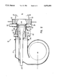
- FIG. 2 shows a diagrammatic partial cross-sectional view of a burner apparatus, according to one preferred embodiment of this invention.
- FIGS. 3-7 show partial cross-sectional views of different preferred embodiments for introducing and mixing primary gaseous fuel into the flow of combustion air.
- a method for reducing nitrogen oxides (NO x ) resulting from gaseous fuel combustion begins with forming or premixing gaseous fuel and excess air to form a fuel-lean mixture.
- Such fuel/air mixture is introduced into primary combustion zone 25 and then combusted thereby forming primary combustion products.
- the primary combustion products are introduced into secondary combustion zone 35.
- both primary combustion zone 25 and secondary combustion zone 35 are located within combustion chamber 16.
- air is intended to be interchangeable with the term "oxidant.” It is apparent that atmospheric air, oxygen, oxygen-enriched air, another suitable oxidant, or any combination thereof can be used to form a combustible mixture with a gaseous fuel, such as natural gas, propane, refinery fuel gas and the like.
- gaseous fuel is intended to include fuels in a gaseous state or any other suitable light liquid hydrocarbon fuel that can be stored as a liquid and then vaporized prior to combustion. Propane is an example of a light liquid hydrocarbon fuel that can be stored as a liquid and then vaporized to form the equivalent of a gaseous fuel, within the context of the specification and the claims.
- Secondary gaseous fuel which can be the same or a different type of fuel as the primary gaseous fuel, is introduced into the secondary combustion zone to form a mixture with the primary combustion products.
- the secondary gaseous fuel and the primary combustion products are preferably mixed and then combusted within secondary combustion zone 35 thereby forming secondary combustion products.
- a portion of the secondary combustion products is internally recirculated and introduced back into the secondary combustion zone, schematically shown in FIG. 1 as occurring completely within combustion chamber 16.
- primary feed means 20 introduce the primary gaseous fuel and excess air within primary combustion zone 25 to form a primary flame envelope within combustion chamber 16.
- Secondary feed means 30 introduce the secondary gaseous fuel into secondary combustion zone 35 to form a secondary flame envelope which peripherally surrounds the primary flame envelope defined by primary combustion zone 25.
- the fuel lean conditions within primary combustion zone 25 also suppress the prompt NO x formation mechanism.
- At least a portion of the overall combustion products are recirculated to primary combustion zone 25.
- the primary gaseous fuel is preferably premixed with the excess combustion air and the overall combustion products, preferably in an amount of approximately 0 to approximately 50% of the total mass flow of the overall combustion products.
- Such premixture produces fuel-lean combustion within primary combustion zone 25, preferably with a fuel equivalence ratio within a range of approximately 0.5 to approximately 0.75.
- the secondary gaseous fuel is injected into the secondary flame envelope, downstream of primary combustion zone 25.
- the secondary gaseous fuel and the primary combustion products are preferably mixed in amounts to form an overall fuel equivalence ratio of approximately 0.75 to approximately 0.95.
- Such overall equivalence ratio results in high thermal efficiencies in conventional combustion apparatuses.
- At least a portion of the fuel/air mixture is bypassed around primary combustion zone 25 and introduced into secondary combustion zone 35, as schematically shown in FIG. 1.
- Such bypass arrangement allows secondary oxidation reactions to proceed more rapidly, but initially under fuel-rich conditions which results in relatively low NO x rates.
- the bypass arrangement also produces a more compact secondary flame envelope. Introducing or entraining secondary combustion products into secondary combustion zone 35 also lowers flame temperatures and thus reduces NO x formation when the second stage of combustion transitions to lean conditions. With the additional mass flow created by the bypass arrangement, the momentum of secondary jets introduced within secondary combustion zone 35 improves controls of the second stage mixing process.
- burner apparatus 15 comprises: primary feed means 20 for mixing primary gaseous fuel with excess air and introducing the resulting fuel/air mixture into primary combustion zone 25; secondary feed means 30 for introducing secondary gaseous fuel into secondary combustion zone 35 which is downstream with respect to primary combustion zone 25; and recirculation means 40 for internally recirculating a portion of the secondary combustion products into secondary combustion zone 35.
- primary feed means 20 comprise a suitably shaped blower housing 21.
- gas manifold 23 is mounted within blower housing 21, such that annular space 22 is formed about a periphery of gas manifold 23.
- gas manifold 23' can be used in lieu of or together with gas manifold 23.
- Mixing means 24 are preferably mounted at a discharge section of gas manifold 23 or 23'.
- Mixing means 24 may comprise a swirler, a bluff body, a diffuser, or any other suitable mixing device known to those skilled in the art.
- FIGS. 3-7 show various sizes, shapes and positions of ports 27 which can be used to inject the primary gaseous fuel into a stream of combustion air or other suitable oxidant that carries the primary gaseous fuel into primary combustion zone 25.
- FIG. 3 shows radial ports 27 which inject the primary gaseous fuel radially inward into oxidant 29 flowing within gas manifold 23.
- FIG. 4 shows radial ports 27 which inject the primary gaseous fuel outwardly into oxidant 28 flowing in an annular space formed between blower housing 21 and gas manifold 23.
- FIG. 5 shows a plurality of closed-end tubes 26 having one or more ports 27 which inject the primary gaseous fuel in a spoked arrangement into oxidant 29 flowing within gas manifold 23.
- FIG. 3 shows radial ports 27 which inject the primary gaseous fuel radially inward into oxidant 29 flowing within gas manifold 23.
- FIG. 4 shows radial ports 27 which inject the primary gaseous fuel outwardly into oxidant 28 flowing in an
- FIG. 6 shows a plurality of closed-end tubes 26 each having one or more ports 27 that inject the primary gaseous fuel into oxidant 28, also in a spoked arrangement.
- FIG. 7 shows the primary gaseous fuel flowing through ports 27 in gas manifold 23' which inject the primary gaseous fuel radially away from gas manifold 23'.
- FIGS. 3-7 show five different preferred embodiments for the arrangement of ports 27.
- Each arrangement preferably comprises between approximately 4 and approximately 32 ports 27 which are preferably equally spaced about the periphery of gas manifold 23 or 23'. It is apparent that the different embodiments can be operated individually or in any suitable combination.
- secondary feed means 30 comprise injection means for forming fluid jets directed toward secondary combustion zone 35.
- the injection means may comprise a plurality of staged gas ports 32, preferably 4 to 16, positioned about annular space 22.
- Each staged gas port 32 is preferably positioned to form the secondary flame envelope so that it peripherally surrounds the primary flame envelope.
- Each staged gas port 32 is aimed radially inward toward the primary flame envelope, preferably at an injection angle A of approximately 0° to approximately 30°.
- FIG. 2 shows staged gas port 32 positioned at injection angle A within such approximate range.
- Each staged gas port 32 forms at least one orifice, preferably 1 to 3 orifices, each of which are in communication with combustion chamber 16.
- staged gas port 32 having a discharge nozzle section with 2 orifices. It is apparent that staged gas ports 32 can have any suitable cross section which is conducive to forming a suitable secondary flame envelope. It is also apparent that each staged gas port 32 can be formed by an inlet tube which is directed radially inward toward primary combustion zone 25 or the primary flame envelope.
- bypass means 50 comprise blower housing 21 having opening 52, as shown in FIG. 2, which forms communication with both primary feed means 20 and secondary feed means 30. It is apparent that bypass means 50 is not necessary for operation of burner apparatus 15 according to this invention, but is preferred. It is also apparent that bypass means 50 may comprise any other suitable conduit, bore or opening that forms communication between primary feed means 20 and secondary feed means 30.
Landscapes
- Engineering & Computer Science (AREA)
- Chemical & Material Sciences (AREA)
- Combustion & Propulsion (AREA)
- Mechanical Engineering (AREA)
- General Engineering & Computer Science (AREA)
Abstract
Description
Claims (14)
Priority Applications (1)
| Application Number | Priority Date | Filing Date | Title |
|---|---|---|---|
| US08/322,758 US5573391A (en) | 1994-10-13 | 1994-10-13 | Method for reducing nitrogen oxides |
Applications Claiming Priority (1)
| Application Number | Priority Date | Filing Date | Title |
|---|---|---|---|
| US08/322,758 US5573391A (en) | 1994-10-13 | 1994-10-13 | Method for reducing nitrogen oxides |
Publications (1)
| Publication Number | Publication Date |
|---|---|
| US5573391A true US5573391A (en) | 1996-11-12 |
Family
ID=23256278
Family Applications (1)
| Application Number | Title | Priority Date | Filing Date |
|---|---|---|---|
| US08/322,758 Expired - Lifetime US5573391A (en) | 1994-10-13 | 1994-10-13 | Method for reducing nitrogen oxides |
Country Status (1)
| Country | Link |
|---|---|
| US (1) | US5573391A (en) |
Cited By (19)
| Publication number | Priority date | Publication date | Assignee | Title |
|---|---|---|---|---|
| US5636977A (en) * | 1994-10-13 | 1997-06-10 | Gas Research Institute | Burner apparatus for reducing nitrogen oxides |
| EP1009952A1 (en) * | 1997-05-13 | 2000-06-21 | Maxon Corporation | Low-emissions industrial burner |
| US6663380B2 (en) | 2001-09-05 | 2003-12-16 | Gas Technology Institute | Method and apparatus for advanced staged combustion utilizing forced internal recirculation |
| US20040228786A1 (en) * | 2003-02-03 | 2004-11-18 | Walter Schicketanz | Oxidative purification of a flue gas containing oxygen and a combustible component |
| US20050112517A1 (en) * | 2003-11-21 | 2005-05-26 | Associated Physics Of America, Llc | Method and device for combusting liquid fuels using hydrogen |
| US20050158684A1 (en) * | 2004-01-15 | 2005-07-21 | Bussman Wesley R. | Remote staged furnace burner configurations and methods |
| US20070172784A1 (en) * | 2006-01-24 | 2007-07-26 | George Stephens | Dual fuel gas-liquid burner |
| US20070172783A1 (en) * | 2006-01-24 | 2007-07-26 | George Stephens | Dual fuel gas-liquid burner |
| US20070172785A1 (en) * | 2006-01-24 | 2007-07-26 | George Stephens | Dual fuel gas-liquid burner |
| EP2002183A2 (en) * | 2006-03-01 | 2008-12-17 | Maxon Corporation | Industrial burner |
| US20120009531A1 (en) * | 2010-07-12 | 2012-01-12 | L'air Liquide Societe Anonyme Pour L'etude Et L'exploitation Des Procedes Georges Claude | Distributed combustion process and burner |
| US20130244187A1 (en) * | 2012-03-19 | 2013-09-19 | Honeywell International Inc. | HIGH EFFICIENCY LOW NOx EMISSION BURNER APPARATUS |
| US20170016615A1 (en) * | 2014-04-10 | 2017-01-19 | Sofinter S.P.A. | Burner |
| US9909755B2 (en) | 2013-03-15 | 2018-03-06 | Fives North American Combustion, Inc. | Low NOx combustion method and apparatus |
| US10281140B2 (en) | 2014-07-15 | 2019-05-07 | Chevron U.S.A. Inc. | Low NOx combustion method and apparatus |
| WO2020124075A1 (en) * | 2018-12-14 | 2020-06-18 | Power Flame Incorporated | Apparatus and method for a burner assembly |
| CN114183754A (en) * | 2020-09-14 | 2022-03-15 | 意大利利雅路股份有限公司 | Burner head of burner |
| WO2023030610A1 (en) * | 2021-08-31 | 2023-03-09 | Ammann Schweiz Ag | Gas-fired burner, in particular for a drying drum of an asphalt mixing plant |
| WO2023126372A1 (en) * | 2021-12-30 | 2023-07-06 | Fives Pillard | Installation comprising a premixing burner |
Citations (16)
| Publication number | Priority date | Publication date | Assignee | Title |
|---|---|---|---|---|
| US3838652A (en) * | 1972-01-06 | 1974-10-01 | Rodenhuis & Verloop Bv | Furnace installation for burning liquid or gaseous fuel, in particular for a boiler |
| US3920377A (en) * | 1973-07-12 | 1975-11-18 | Ishikawajima Harima Heavy Ind | Combustion apparatus |
| US4230445A (en) * | 1977-06-17 | 1980-10-28 | Sulzer Brothers Ltd. | Burner for a fluid fuel |
| US4575332A (en) * | 1983-07-30 | 1986-03-11 | Deutsche Babcock Werke Aktiengesellschaft | Method of and burner for burning liquid or gaseous fuels with decreased NOx formation |
| US4995807A (en) * | 1989-03-20 | 1991-02-26 | Bryan Steam Corporation | Flue gas recirculation system |
| US5013236A (en) * | 1989-05-22 | 1991-05-07 | Institute Of Gas Technology | Ultra-low pollutant emission combustion process and apparatus |
| US5044932A (en) * | 1989-10-19 | 1991-09-03 | It-Mcgill Pollution Control Systems, Inc. | Nitrogen oxide control using internally recirculated flue gas |
| US5073105A (en) * | 1991-05-01 | 1991-12-17 | Callidus Technologies Inc. | Low NOx burner assemblies |
| US5098282A (en) * | 1990-09-07 | 1992-03-24 | John Zink Company | Methods and apparatus for burning fuel with low NOx formation |
| US5129818A (en) * | 1990-09-14 | 1992-07-14 | Benno Balsiger | Method of feeding back exhaust gases in oil and gas burners |
| US5158445A (en) * | 1989-05-22 | 1992-10-27 | Institute Of Gas Technology | Ultra-low pollutant emission combustion method and apparatus |
| US5195884A (en) * | 1992-03-27 | 1993-03-23 | John Zink Company, A Division Of Koch Engineering Company, Inc. | Low NOx formation burner apparatus and methods |
| US5209187A (en) * | 1991-08-01 | 1993-05-11 | Institute Of Gas Technology | Low pollutant - emission, high efficiency cyclonic burner for firetube boilers and heaters |
| US5275554A (en) * | 1990-08-31 | 1994-01-04 | Power-Flame, Inc. | Combustion system with low NOx adapter assembly |
| US5350293A (en) * | 1993-07-20 | 1994-09-27 | Institute Of Gas Technology | Method for two-stage combustion utilizing forced internal recirculation |
| US5403181A (en) * | 1992-06-05 | 1995-04-04 | Nippon Furnace Kogyo Kaisha, Ltd | Method of low-NOx combustion and burner device for effecting same |
-
1994
- 1994-10-13 US US08/322,758 patent/US5573391A/en not_active Expired - Lifetime
Patent Citations (16)
| Publication number | Priority date | Publication date | Assignee | Title |
|---|---|---|---|---|
| US3838652A (en) * | 1972-01-06 | 1974-10-01 | Rodenhuis & Verloop Bv | Furnace installation for burning liquid or gaseous fuel, in particular for a boiler |
| US3920377A (en) * | 1973-07-12 | 1975-11-18 | Ishikawajima Harima Heavy Ind | Combustion apparatus |
| US4230445A (en) * | 1977-06-17 | 1980-10-28 | Sulzer Brothers Ltd. | Burner for a fluid fuel |
| US4575332A (en) * | 1983-07-30 | 1986-03-11 | Deutsche Babcock Werke Aktiengesellschaft | Method of and burner for burning liquid or gaseous fuels with decreased NOx formation |
| US4995807A (en) * | 1989-03-20 | 1991-02-26 | Bryan Steam Corporation | Flue gas recirculation system |
| US5158445A (en) * | 1989-05-22 | 1992-10-27 | Institute Of Gas Technology | Ultra-low pollutant emission combustion method and apparatus |
| US5013236A (en) * | 1989-05-22 | 1991-05-07 | Institute Of Gas Technology | Ultra-low pollutant emission combustion process and apparatus |
| US5044932A (en) * | 1989-10-19 | 1991-09-03 | It-Mcgill Pollution Control Systems, Inc. | Nitrogen oxide control using internally recirculated flue gas |
| US5275554A (en) * | 1990-08-31 | 1994-01-04 | Power-Flame, Inc. | Combustion system with low NOx adapter assembly |
| US5098282A (en) * | 1990-09-07 | 1992-03-24 | John Zink Company | Methods and apparatus for burning fuel with low NOx formation |
| US5129818A (en) * | 1990-09-14 | 1992-07-14 | Benno Balsiger | Method of feeding back exhaust gases in oil and gas burners |
| US5073105A (en) * | 1991-05-01 | 1991-12-17 | Callidus Technologies Inc. | Low NOx burner assemblies |
| US5209187A (en) * | 1991-08-01 | 1993-05-11 | Institute Of Gas Technology | Low pollutant - emission, high efficiency cyclonic burner for firetube boilers and heaters |
| US5195884A (en) * | 1992-03-27 | 1993-03-23 | John Zink Company, A Division Of Koch Engineering Company, Inc. | Low NOx formation burner apparatus and methods |
| US5403181A (en) * | 1992-06-05 | 1995-04-04 | Nippon Furnace Kogyo Kaisha, Ltd | Method of low-NOx combustion and burner device for effecting same |
| US5350293A (en) * | 1993-07-20 | 1994-09-27 | Institute Of Gas Technology | Method for two-stage combustion utilizing forced internal recirculation |
Cited By (36)
| Publication number | Priority date | Publication date | Assignee | Title |
|---|---|---|---|---|
| US5636977A (en) * | 1994-10-13 | 1997-06-10 | Gas Research Institute | Burner apparatus for reducing nitrogen oxides |
| EP1009952A1 (en) * | 1997-05-13 | 2000-06-21 | Maxon Corporation | Low-emissions industrial burner |
| EP1009952A4 (en) * | 1997-05-13 | 2001-05-02 | Maxon Corp | Low-emissions industrial burner |
| US6663380B2 (en) | 2001-09-05 | 2003-12-16 | Gas Technology Institute | Method and apparatus for advanced staged combustion utilizing forced internal recirculation |
| US20040228786A1 (en) * | 2003-02-03 | 2004-11-18 | Walter Schicketanz | Oxidative purification of a flue gas containing oxygen and a combustible component |
| US20050112517A1 (en) * | 2003-11-21 | 2005-05-26 | Associated Physics Of America, Llc | Method and device for combusting liquid fuels using hydrogen |
| US7153129B2 (en) | 2004-01-15 | 2006-12-26 | John Zink Company, Llc | Remote staged furnace burner configurations and methods |
| US20050158684A1 (en) * | 2004-01-15 | 2005-07-21 | Bussman Wesley R. | Remote staged furnace burner configurations and methods |
| CN1721763B (en) * | 2004-03-24 | 2011-06-01 | 约翰津克有限责任公司 | Remote staged furnace burner configurations and methods |
| EP1580484A3 (en) * | 2004-03-24 | 2006-04-05 | John Zink Company,L.L.C. | Remote staged furnace burner configurations and methods |
| EP1580484A2 (en) | 2004-03-24 | 2005-09-28 | John Zink Company,L.L.C. | Remote staged furnace burner configurations and methods |
| US7909601B2 (en) | 2006-01-24 | 2011-03-22 | Exxonmobil Chemical Patents Inc. | Dual fuel gas-liquid burner |
| US20070172784A1 (en) * | 2006-01-24 | 2007-07-26 | George Stephens | Dual fuel gas-liquid burner |
| US20070172783A1 (en) * | 2006-01-24 | 2007-07-26 | George Stephens | Dual fuel gas-liquid burner |
| US20070172785A1 (en) * | 2006-01-24 | 2007-07-26 | George Stephens | Dual fuel gas-liquid burner |
| US8075305B2 (en) * | 2006-01-24 | 2011-12-13 | Exxonmobil Chemical Patents Inc. | Dual fuel gas-liquid burner |
| US7901204B2 (en) | 2006-01-24 | 2011-03-08 | Exxonmobil Chemical Patents Inc. | Dual fuel gas-liquid burner |
| US8308477B2 (en) | 2006-03-01 | 2012-11-13 | Honeywell International Inc. | Industrial burner |
| US20100190119A1 (en) * | 2006-03-01 | 2010-07-29 | Honeywell International Inc. | Industrial burner |
| EP2002183A2 (en) * | 2006-03-01 | 2008-12-17 | Maxon Corporation | Industrial burner |
| US8506287B2 (en) | 2006-03-01 | 2013-08-13 | Honeywell International Inc. | Industrial burner |
| EP2002183A4 (en) * | 2006-03-01 | 2010-12-29 | Maxon Corp | Industrial burner |
| US20120009531A1 (en) * | 2010-07-12 | 2012-01-12 | L'air Liquide Societe Anonyme Pour L'etude Et L'exploitation Des Procedes Georges Claude | Distributed combustion process and burner |
| US20130244187A1 (en) * | 2012-03-19 | 2013-09-19 | Honeywell International Inc. | HIGH EFFICIENCY LOW NOx EMISSION BURNER APPARATUS |
| US9909755B2 (en) | 2013-03-15 | 2018-03-06 | Fives North American Combustion, Inc. | Low NOx combustion method and apparatus |
| US10612773B2 (en) * | 2014-04-10 | 2020-04-07 | Sofinter S.P.A. | Burner |
| US20170016615A1 (en) * | 2014-04-10 | 2017-01-19 | Sofinter S.P.A. | Burner |
| US10281140B2 (en) | 2014-07-15 | 2019-05-07 | Chevron U.S.A. Inc. | Low NOx combustion method and apparatus |
| WO2020124075A1 (en) * | 2018-12-14 | 2020-06-18 | Power Flame Incorporated | Apparatus and method for a burner assembly |
| CN114183754A (en) * | 2020-09-14 | 2022-03-15 | 意大利利雅路股份有限公司 | Burner head of burner |
| EP3967924A1 (en) * | 2020-09-14 | 2022-03-16 | Riello S.p.A. | Combustion head for a burner |
| US11841137B2 (en) | 2020-09-14 | 2023-12-12 | Riello, S.P.A. | Combustion head for a burner |
| CN114183754B (en) * | 2020-09-14 | 2024-04-26 | 意大利利雅路股份有限公司 | Burner head of burner |
| WO2023030610A1 (en) * | 2021-08-31 | 2023-03-09 | Ammann Schweiz Ag | Gas-fired burner, in particular for a drying drum of an asphalt mixing plant |
| WO2023126372A1 (en) * | 2021-12-30 | 2023-07-06 | Fives Pillard | Installation comprising a premixing burner |
| FR3131621A1 (en) * | 2021-12-30 | 2023-07-07 | Fives Pillard | Installation comprising a premix burner |
Similar Documents
| Publication | Publication Date | Title |
|---|---|---|
| US5636977A (en) | Burner apparatus for reducing nitrogen oxides | |
| US5573391A (en) | Method for reducing nitrogen oxides | |
| US5269679A (en) | Staged air, recirculating flue gas low NOx burner | |
| CA2107630C (en) | Inspirated staged combustion burner | |
| EP0782681B1 (en) | Ultra low nox burner | |
| US5413477A (en) | Staged air, low NOX burner with internal recuperative flue gas recirculation | |
| US5098282A (en) | Methods and apparatus for burning fuel with low NOx formation | |
| KR100394428B1 (en) | FUEL DILUTION METHODS AND APPARATUS FOR NOx REDUCTION | |
| EP0972160B1 (en) | LOW NOx FLAT FLAME BURNER | |
| EP1167878B1 (en) | Fuel dilution methods and apparatus for NOx reduction | |
| US5807094A (en) | Air premixed natural gas burner | |
| US7025587B2 (en) | Burner with high capacity venturi | |
| EP0575043B1 (en) | Fuel-burner method and apparatus | |
| US5269678A (en) | Methods and apparatus for burning fuel with low NOx formation | |
| EP0738854B1 (en) | A low nitrogen oxide producing combustion method and apparatus | |
| US20040248054A1 (en) | Low NOx emissions, low noise burner assembly and method for reducing the NOx content of furnace flue gas | |
| EP0076036B1 (en) | Method and apparatus for burning fuel in stages | |
| US5681159A (en) | Process and apparatus for low NOx staged-air combustion | |
| US6866502B2 (en) | Burner system employing flue gas recirculation | |
| US6986658B2 (en) | Burner employing steam injection | |
| US6887068B2 (en) | Centering plate for burner | |
| EP1495262B1 (en) | Burner system with improved flue gas recirculation | |
| WO2023187215A1 (en) | Gas burner with low nox emission | |
| Syska et al. | Staged air, recirculating flue gas low NO x burner | |
| Martin et al. | Staged fuel and air for low NO x burner |
Legal Events
| Date | Code | Title | Description |
|---|---|---|---|
| AS | Assignment |
Owner name: POWER FLAME INCORPORATED, KANSAS Free format text: ASSIGNMENT OF ASSIGNORS INTEREST;ASSIGNORS:COLE, ROBERT;WIENER, WILLIAM A.;REEL/FRAME:007524/0126 Effective date: 19950530 |
|
| AS | Assignment |
Owner name: ARTHUR D. LITTLE, INC., MASSACHUSETTS Free format text: ASSIGNMENT OF ASSIGNORS INTEREST;ASSIGNORS:BENSON, CHARLES E.;LOFTUS, PETER J.;REEL/FRAME:007572/0034 Effective date: 19950713 |
|
| AS | Assignment |
Owner name: GAS RESEARCH INSTITUTE, ILLINOIS Free format text: ASSIGNMENT OF ASSIGNORS INTEREST;ASSIGNOR:POWER FLAME INCORPORATED;REEL/FRAME:007650/0963 Effective date: 19950811 |
|
| AS | Assignment |
Owner name: GAS RESEARCH INSTITUTE, ILLINOIS Free format text: ASSIGNMENT OF ASSIGNORS INTEREST;ASSIGNOR:ARTHUR D. LITTLE, INC.;REEL/FRAME:007643/0285 Effective date: 19950824 |
|
| STCF | Information on status: patent grant |
Free format text: PATENTED CASE |
|
| FEPP | Fee payment procedure |
Free format text: PAT HLDR NO LONGER CLAIMS SMALL ENT STAT AS NONPROFIT ORG (ORIGINAL EVENT CODE: LSM3); ENTITY STATUS OF PATENT OWNER: SMALL ENTITY |
|
| FEPP | Fee payment procedure |
Free format text: PAYOR NUMBER ASSIGNED (ORIGINAL EVENT CODE: ASPN); ENTITY STATUS OF PATENT OWNER: SMALL ENTITY |
|
| FPAY | Fee payment |
Year of fee payment: 4 |
|
| FPAY | Fee payment |
Year of fee payment: 8 |
|
| AS | Assignment |
Owner name: GAS TECHNOLOGY INSTITUTE, ILLINOIS Free format text: ASSIGNMENT OF ASSIGNORS INTEREST;ASSIGNOR:GAS RESEARCH INSTITUTE;REEL/FRAME:017448/0282 Effective date: 20060105 |
|
| FEPP | Fee payment procedure |
Free format text: PAT HOLDER CLAIMS SMALL ENTITY STATUS, ENTITY STATUS SET TO SMALL (ORIGINAL EVENT CODE: LTOS); ENTITY STATUS OF PATENT OWNER: SMALL ENTITY |
|
| FEPP | Fee payment procedure |
Free format text: PAT HOLDER NO LONGER CLAIMS SMALL ENTITY STATUS, ENTITY STATUS SET TO UNDISCOUNTED (ORIGINAL EVENT CODE: STOL); ENTITY STATUS OF PATENT OWNER: SMALL ENTITY Free format text: PAT HOLDER CLAIMS SMALL ENTITY STATUS, ENTITY STATUS SET TO SMALL (ORIGINAL EVENT CODE: LTOS); ENTITY STATUS OF PATENT OWNER: SMALL ENTITY |
|
| REFU | Refund |
Free format text: REFUND - PAYMENT OF MAINTENANCE FEE, 12TH YEAR, LARGE ENTITY (ORIGINAL EVENT CODE: R1553); ENTITY STATUS OF PATENT OWNER: SMALL ENTITY |
|
| FPAY | Fee payment |
Year of fee payment: 12 |
|
| REMI | Maintenance fee reminder mailed | ||
| FEPP | Fee payment procedure |
Free format text: ENTITY STATUS SET TO SMALL (ORIGINAL EVENT CODE: SMAL); ENTITY STATUS OF PATENT OWNER: SMALL ENTITY |