US5553795A - Inertial impactor with a specially designed impaction plate - Google Patents
Inertial impactor with a specially designed impaction plate Download PDFInfo
- Publication number
- US5553795A US5553795A US08/436,727 US43672795A US5553795A US 5553795 A US5553795 A US 5553795A US 43672795 A US43672795 A US 43672795A US 5553795 A US5553795 A US 5553795A
- Authority
- US
- United States
- Prior art keywords
- particles
- plate
- impaction
- collection efficiency
- nozzle
- Prior art date
- Legal status (The legal status is an assumption and is not a legal conclusion. Google has not performed a legal analysis and makes no representation as to the accuracy of the status listed.)
- Expired - Lifetime
Links
Images


Classifications
-
- B—PERFORMING OPERATIONS; TRANSPORTING
- B02—CRUSHING, PULVERISING, OR DISINTEGRATING; PREPARATORY TREATMENT OF GRAIN FOR MILLING
- B02C—CRUSHING, PULVERISING, OR DISINTEGRATING IN GENERAL; MILLING GRAIN
- B02C19/00—Other disintegrating devices or methods
- B02C19/06—Jet mills
- B02C19/066—Jet mills of the jet-anvil type
Definitions
- Blowing away of the particles from the impaction plate is another problem of the conventional impactor.
- the particles When the particles have been accumulated to a certain thickness on the plate, the particles will be blown away by the air stream, causing another loss of particles.
- the main objective of the present invention is to provide an inertial impactor with a specially designed impaction plate to eliminate the aforesaid problems. It comprises a nozzle protruding from the nozzle plate; an impaction plate and formed with a conical recess covered by an orifice plate, and a circular plane at the bottom of the recess having a diameter slightly greater than the nozzle.
- This design is to change the direction of incoming or rebounding particles in the conventional inertial impactor with a flat plate, in order to recapture rebounding particles and to overcome the problem of blowing away of particles from the impaction plate which results in lowering of collection efficiency, and to increase the collection capacity of the impaction plate.
- FIG. 1 illustrates the principle of particle collection by the inertial impactor
- FIG. 2 is a sectional view of a conventional inertial impactor with a flat impaction plate
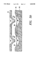
- FIG. 3A and 3B are sectional views of inertial impactors according to the present invention.
- FIG. 4 is a graph illustrating the relationship between the collection efficiency for solid particles and particle loading (with greased impaction plate);
- FIG. 5A is a graphical representation illustrating the relationship between the collection efficiency and the square root of the Stokes number by the conventional inertial impactor with a flat impaction plate;
- FIG. 5B is a graphical representation the relationship between the collection efficiency for solid particles and the square root of the Stokes number by the present invention (with ungreased impaction plate);
- FIG. 6 is a graph illustrating the relationship between the collection for solid particles and the square root of the Stokes number (with ungreased impaction plate);
- FIG. 7A is a graphical representation illustrating the relationship between the collection for solid particles and the square root of the Stokes number by the conventional inertial impactor with a flat impaction plate (ungreased);
- FIG. 7B is a graphical representation illustrating the relationship between the collection efficiency and the square root of the Stokes number by the present invention (with ungreased impaction plate).
- FIG. 1 illustrates the principle of particle collection in a typical inertial impactor.
- the air stream is accelerated so that the particles 11 in the stream have a greater inertia.
- the particles 11 with sufficient inertia deviate from their respective streamlines 14 and impinge upon the impaction plate 13.
- FIG. 2 a sectional view of a conventional inertial impactor with a flat impaction plate, it comprises mainly a nozzle element 21 and a flat impaction plate 22. There is a gap 23 between the nozzle element 21 and the impaction plate 22. The particles 11 rebounding from the flat impaction plate 22 can be easily brought away from the flat impaction plate 22 by the air stream. Then, the actual collection efficiency is much lower than the theoretical collection efficiency. Moreover, after the particles 11 are accumulated on the impaction plate 22 to a certain thickness, the particles 11 can be blown away by the air stream, resulting in loss of particles 11.
- FIGS. 3A and 3B are sectional view of an inertial impactor according to the present invention.
- the impactor according to the present invention comprises a nozzle element 31 and an impaction plate 32.
- the nozzle element 31 has a protruding nozzle 33, and the impaction plate 32 is formed with a conical recess 35 covered by an orifice plate 34.
- a circular impaction plane 36 with a diameter slightly greater than the diameter 37 of the nozzle 33 is located at the bottom of the conical recess 35, which is designed so that the collection efficiency curve for the particles 11 is relatively close to the Marple's theoretical collection efficiency curve (Marple, V. A. and Liu B.Y.H., Characteristics of Laminar Jet Impactor, Environmental Science and Technology, Vol.
- the orifice diameter 38 of the orifice plate 34 is about four times of the diameter 37 of the nozzle 33. It is an appropriate size which prevents loss of particles 11 due to unfavorable exiting flow direction if the orifice size is too small, and loss of particles 11 due to blowing out in case the orifice size is too large. It is a design which effectively retains the particles 11 within the conical recess 35 and prevents the particles 11 from being blown out of the conical recess 35 by the air stream. The particles 11 can also be accumulated quickly on the bottom of the conical recess 35 to improve collection efficiency.
- FIG. 4 shows the relationship between the solid particle collection efficiency and particle loading with greased impaction plate.
- the upper horizontal axis represents loading in mg (P)
- the lower horizontal axis represents the dimensionless number of particle layers (N) which is the ratio of the total projected area of the loaded particles to the cross sectional area of the nozzle
- the vertical axis represents the collection efficiency (C) in percentage.
- FIGS. 5A and 5B illustrate the relationship between the solid particle collection efficiency and a dimensionless particle size expressed in the square root of the Stokes number in the inertial impaction with a greased conventional flat impaction plate and the present invention with a greased impaction plate respectively.
- the horizontal axis represents the square root of the Stokes number (S)
- the vertical axis represents the collection efficiency (C) in percentage. From these figures it can be seen that the present invention has a collection efficiency very similar to the conventional impactor when particle loading is light. However, when the particles loading is heavy, the collection efficiency of the conventional impactor falls down significantly, being only 40% to 70% at a high Stokes number.
- d 1 diameter of circular throat or width of rectangular throat
- FIG. 6 Please refer to FIG. 6 for the collection efficiency for solid particles and particle loading (with ungreased impaction plate).
- the upper horizontal axis represents particle loading in mg (P);
- the lower horizontal axis represents the dimensionless number of particle layers (N) which is the ratio of the total projected area of the loaded particles to the cross sectional area of the nozzle;
- the vertical axis represents collection efficiency, % (C).
- P particle loading in mg
- N dimensionless number of particle layers
- C collection efficiency
- the incoming particles 11 may impinge on a lateral side of the previously deposited particles. This phenomenon increases a force component for downward movement during particle rebounding, and consequently lowers the possibility of rebounding and improves the collection efficiency. As a result, the present invention can recapture rebounding particles efficiently and raise the collection efficiency to 85% rapidly.
- the collection efficiency of the conventional impactor increases slowly with particle loading. Its maximum collection efficiency is only 55%.
- FIGS. 7A and 7B illustrate the collection efficiency for solid particles and the square root of the Stokes number for the conventional inertial impactor with a flat impaction plate and the impactor according to the present invention (all with ungreased impaction plate) respectively.
- the horizontal axis represents the square root of the Stokes number (S)
- the vertical axis represents collection efficiency, % (C). From these figures it can be seen that the collection efficiency achieved by the present invention is much higher than the conventional impactor.
- the present invention has the following advantages:
- the present invention lowers radial fluid speed so that less rebounded solid particles will be brought away from the impaction plate by the high radial fluid speed.
- the particles have a great opportunity to be adhered in the recess because of the use of a protruding nozzle and a conical recess as well as the greater gap between the nozzle and the impaction plate than the conventional impactor.
- the fluid entering the recess must turn its direction and exit from the center of the orifice, and hence the rebounding particles or the particles blown away from the accumulated particles layer can be trapped efficiently while the fluid is turning its direction, consequently collection efficiency and particle loading can be increased.
- the conical recess is designed to expedite particle accumulation on the bottom without the use of viscous substance to increase particle collection efficiency rapidly.
- the diameter of the orifice is about four times of the diameter of the nozzle, which is an appropriate size to prevent loss of particles due to unfavorable exiting flow direction if the orifice size is too small, and prevent loss of particles due to blowing out if the orifice size is too large.
Landscapes
- Engineering & Computer Science (AREA)
- Food Science & Technology (AREA)
- Sampling And Sample Adjustment (AREA)
Abstract
An inertial impactor with a specially designed impaction plate has a nozzle protruding from a nozzle plate, and an impaction plate formed with a conical recess covered by an orifice plate and a circular impaction plane at the bottom of the recess having a diameter slightly greater than that of the diameter of the nozzle. The impactor reduces loss of particles due to rebounding or blowing off particles from the impaction plate so as to increase particle collection efficiency and capacity, permit a quick accumulation of the particles on the bottom of the conical recess, and increase collection efficiency accordingly.
Description
As one of the widely used atmospheric particle samplers an impactor is used for measurement of aerosol size distribution and collection of samples for further chemical analysis. Though it has been used widely, there are still problems to be overcome. When the suspended particles are liquid, its actual collection efficiency is very close to the theoretical collection efficiency. However, when it is used in the collection of solid particles, the collection efficiency is much lower than the theoretical efficiency because solid particles will rebound from the impaction plate, and the rebounded particles can be easily carried away by the aerosol stream if the conventional fiat impaction plate is used.
There are ways to reduce particle rebounding from the impaction plate, such as application of grease on the surface of the impaction plate. However, two essential questions exist in this method: firstly the chemical properties of the grease itself will interfere with chemical analysis of the collected particles; and secondly the incoming particles will rebound from the particles that have been adhered to the impaction plate. Consequently the collection efficiency is lowered.
Blowing away of the particles from the impaction plate is another problem of the conventional impactor. When the particles have been accumulated to a certain thickness on the plate, the particles will be blown away by the air stream, causing another loss of particles.
The main objective of the present invention is to provide an inertial impactor with a specially designed impaction plate to eliminate the aforesaid problems. It comprises a nozzle protruding from the nozzle plate; an impaction plate and formed with a conical recess covered by an orifice plate, and a circular plane at the bottom of the recess having a diameter slightly greater than the nozzle. This design is to change the direction of incoming or rebounding particles in the conventional inertial impactor with a flat plate, in order to recapture rebounding particles and to overcome the problem of blowing away of particles from the impaction plate which results in lowering of collection efficiency, and to increase the collection capacity of the impaction plate.
The invention, as well as its many advantages, may be further understood by the following detailed description and in which:
FIG. 1 illustrates the principle of particle collection by the inertial impactor;
FIG. 2 is a sectional view of a conventional inertial impactor with a flat impaction plate;
FIG. 3A and 3B are sectional views of inertial impactors according to the present invention;
FIG. 4 is a graph illustrating the relationship between the collection efficiency for solid particles and particle loading (with greased impaction plate);
FIG. 5A is a graphical representation illustrating the relationship between the collection efficiency and the square root of the Stokes number by the conventional inertial impactor with a flat impaction plate;
FIG. 5B is a graphical representation the relationship between the collection efficiency for solid particles and the square root of the Stokes number by the present invention (with ungreased impaction plate);
FIG. 6 is a graph illustrating the relationship between the collection for solid particles and the square root of the Stokes number (with ungreased impaction plate);
FIG. 7A is a graphical representation illustrating the relationship between the collection for solid particles and the square root of the Stokes number by the conventional inertial impactor with a flat impaction plate (ungreased); and
FIG. 7B is a graphical representation illustrating the relationship between the collection efficiency and the square root of the Stokes number by the present invention (with ungreased impaction plate).
Please refer to FIG. 1 which illustrates the principle of particle collection in a typical inertial impactor. As the particles 11 in an aerosol stream are passing through the nozzle 12, the air stream is accelerated so that the particles 11 in the stream have a greater inertia. When the air stream impinges upon an impaction plate 13, the particles 11 with sufficient inertia deviate from their respective streamlines 14 and impinge upon the impaction plate 13.
As shown in FIG. 2, a sectional view of a conventional inertial impactor with a flat impaction plate, it comprises mainly a nozzle element 21 and a flat impaction plate 22. There is a gap 23 between the nozzle element 21 and the impaction plate 22. The particles 11 rebounding from the flat impaction plate 22 can be easily brought away from the flat impaction plate 22 by the air stream. Then, the actual collection efficiency is much lower than the theoretical collection efficiency. Moreover, after the particles 11 are accumulated on the impaction plate 22 to a certain thickness, the particles 11 can be blown away by the air stream, resulting in loss of particles 11.
FIGS. 3A and 3B are sectional view of an inertial impactor according to the present invention. The impactor according to the present invention comprises a nozzle element 31 and an impaction plate 32. The nozzle element 31 has a protruding nozzle 33, and the impaction plate 32 is formed with a conical recess 35 covered by an orifice plate 34. A circular impaction plane 36 with a diameter slightly greater than the diameter 37 of the nozzle 33 is located at the bottom of the conical recess 35, which is designed so that the collection efficiency curve for the particles 11 is relatively close to the Marple's theoretical collection efficiency curve (Marple, V. A. and Liu B.Y.H., Characteristics of Laminar Jet Impactor, Environmental Science and Technology, Vol. 8, pp 648-654, 1974). The orifice diameter 38 of the orifice plate 34 is about four times of the diameter 37 of the nozzle 33. It is an appropriate size which prevents loss of particles 11 due to unfavorable exiting flow direction if the orifice size is too small, and loss of particles 11 due to blowing out in case the orifice size is too large. It is a design which effectively retains the particles 11 within the conical recess 35 and prevents the particles 11 from being blown out of the conical recess 35 by the air stream. The particles 11 can also be accumulated quickly on the bottom of the conical recess 35 to improve collection efficiency.
FIG. 4 shows the relationship between the solid particle collection efficiency and particle loading with greased impaction plate. The upper horizontal axis represents loading in mg (P), the lower horizontal axis represents the dimensionless number of particle layers (N) which is the ratio of the total projected area of the loaded particles to the cross sectional area of the nozzle, and the vertical axis represents the collection efficiency (C) in percentage. As shown in FIG. 4, it has been proved by experiment that, there is no significant difference in initial collection efficiency between the present invention and the conventional impactor. However, as the particles 11 gradually accumulate on the impaction plate, the collection efficiency of the conventional impactor drops rapidly while that of the present invention maintains relatively high and stable after particle loading reaches a certain level.
FIGS. 5A and 5B illustrate the relationship between the solid particle collection efficiency and a dimensionless particle size expressed in the square root of the Stokes number in the inertial impaction with a greased conventional flat impaction plate and the present invention with a greased impaction plate respectively. In these figures, the horizontal axis represents the square root of the Stokes number (S), while the vertical axis represents the collection efficiency (C) in percentage. From these figures it can be seen that the present invention has a collection efficiency very similar to the conventional impactor when particle loading is light. However, when the particles loading is heavy, the collection efficiency of the conventional impactor falls down significantly, being only 40% to 70% at a high Stokes number. But with the present invention, a relatively high collection efficiency of up to 85% to 90% can be maintained at a high Stokes number because the present invention recaptures the rebounded particles 11. After the particles loading on the impaction plate 32 has reached a certain value, the collection efficiency for the particles 11 maintained nearly constant.
Conventionally the Stokes number is defined as the ratio of the particle stopping distance to the halfwidth of the radius of the impactor throat, expressed as: ##EQU1## in which da =particle diameter
U=mean air velocity at the throat
Cc =slip correction factor
d1 =diameter of circular throat or width of rectangular throat
ρ0 =particle density
Normally, the impaction efficiency of impactor varies according to the Stokes number.
Please refer to FIG. 6 for the collection efficiency for solid particles and particle loading (with ungreased impaction plate). In this figure, the upper horizontal axis represents particle loading in mg (P); the lower horizontal axis represents the dimensionless number of particle layers (N) which is the ratio of the total projected area of the loaded particles to the cross sectional area of the nozzle; and the vertical axis represents collection efficiency, % (C). In the initial sampling stage, both the present invention and the conventional impactor will encounter rebounding of the particles 11. But in the present invention, because the particles 11 accumulate on the bottom of the conical recess 35 rapidly, the collection efficiency also increases rapidly. The rapid increase in collection efficiency is due to the displacement or turning of the previously deposited particles 11 by the incoming particles 11 and the consequent lowering of the rebounding energy. Moreover, the incoming particles 11 may impinge on a lateral side of the previously deposited particles. This phenomenon increases a force component for downward movement during particle rebounding, and consequently lowers the possibility of rebounding and improves the collection efficiency. As a result, the present invention can recapture rebounding particles efficiently and raise the collection efficiency to 85% rapidly. On the other hand, the collection efficiency of the conventional impactor increases slowly with particle loading. Its maximum collection efficiency is only 55%.
FIGS. 7A and 7B illustrate the collection efficiency for solid particles and the square root of the Stokes number for the conventional inertial impactor with a flat impaction plate and the impactor according to the present invention (all with ungreased impaction plate) respectively. In these figures the horizontal axis represents the square root of the Stokes number (S), the vertical axis represents collection efficiency, % (C). From these figures it can be seen that the collection efficiency achieved by the present invention is much higher than the conventional impactor.
As described above, the present invention has the following advantages:
1. Under the same S/W ratio (where S is the jet-to-plate distance and W is the jet width or diameter), the present invention lowers radial fluid speed so that less rebounded solid particles will be brought away from the impaction plate by the high radial fluid speed. The particles have a great opportunity to be adhered in the recess because of the use of a protruding nozzle and a conical recess as well as the greater gap between the nozzle and the impaction plate than the conventional impactor.
2. The fluid entering the recess must turn its direction and exit from the center of the orifice, and hence the rebounding particles or the particles blown away from the accumulated particles layer can be trapped efficiently while the fluid is turning its direction, consequently collection efficiency and particle loading can be increased.
3. The conical recess is designed to expedite particle accumulation on the bottom without the use of viscous substance to increase particle collection efficiency rapidly.
4. The diameter of the orifice is about four times of the diameter of the nozzle, which is an appropriate size to prevent loss of particles due to unfavorable exiting flow direction if the orifice size is too small, and prevent loss of particles due to blowing out if the orifice size is too large.
Many changes and modifications in the above embodiment of the invention can, of course, be carried out without departing from the scope thereof. Accordingly, to promote the progress in science and the useful arts, the invention is disclosed and is intended to be limited only by the scope of the appended claims.
Claims (2)
1. An inertial impactor with an impaction plate, comprising:
a nozzle element comprising a nozzle protruding from a nozzle plate; and
an impaction plate formed with a conical recess partially covered by an orifice plate having an orifice, the conical recess having a circular impaction plane at a bottom of the recess with a diameter greater than a diameter of the protruding nozzle, a diameter of the orifice plate being approximately four times the diameter of the protruding nozzle so as to prevent loss of particles if the orifice size is too small, prevent loss of particles due to blowing out if the orifice size is too large, and to effectively retain the particles within the conical recess and prevent particles from being blown out of the conical recess by an air stream so that the particles can be accumulated quickly on the bottom of the conical recess and the collection efficiency can be improved accordingly.
2. The inertial impactor with an impaction plate as claimed in claim 1 further comprising a plurality of nozzles.
Priority Applications (1)
| Application Number | Priority Date | Filing Date | Title |
|---|---|---|---|
| US08/436,727 US5553795A (en) | 1995-05-08 | 1995-05-08 | Inertial impactor with a specially designed impaction plate |
Applications Claiming Priority (1)
| Application Number | Priority Date | Filing Date | Title |
|---|---|---|---|
| US08/436,727 US5553795A (en) | 1995-05-08 | 1995-05-08 | Inertial impactor with a specially designed impaction plate |
Publications (1)
| Publication Number | Publication Date |
|---|---|
| US5553795A true US5553795A (en) | 1996-09-10 |
Family
ID=23733576
Family Applications (1)
| Application Number | Title | Priority Date | Filing Date |
|---|---|---|---|
| US08/436,727 Expired - Lifetime US5553795A (en) | 1995-05-08 | 1995-05-08 | Inertial impactor with a specially designed impaction plate |
Country Status (1)
| Country | Link |
|---|---|
| US (1) | US5553795A (en) |
Cited By (21)
| Publication number | Priority date | Publication date | Assignee | Title |
|---|---|---|---|---|
| WO2001048453A2 (en) * | 1999-11-12 | 2001-07-05 | The Trustees Of The University Of Pennsylvania | Minute devices and integrated systems for particle size detection, separation and collection based on low temperature co-fired ceramic (ltcc) tape technology |
| US6435043B1 (en) | 1999-03-31 | 2002-08-20 | President And Fellows Of Harvard College | Impaction substrate and methods of use |
| US20040232052A1 (en) * | 1998-11-13 | 2004-11-25 | Call Charles John | Methods and devices for continuous sampling of airborne particles using a regenerative surface |
| US20050190058A1 (en) * | 2004-03-01 | 2005-09-01 | Call Charles J. | Networks with sensors for air safety and security |
| US20050247868A1 (en) * | 2004-03-01 | 2005-11-10 | Call Charles J | Biological alarm |
| US20060257287A1 (en) * | 1998-11-13 | 2006-11-16 | Call Charles J | Robust system for screening enclosed spaces for biological agents |
| US20070048186A1 (en) * | 1998-11-13 | 2007-03-01 | Mesosystems Technology, Inc. | Removing surface deposits of concentrated collected particles |
| DE102006023714A1 (en) * | 2006-05-19 | 2007-11-22 | Dräger Safety AG & Co. KGaA | Apparatus and method for selectively determining the amount of oil mist |
| US7799567B1 (en) | 1999-03-10 | 2010-09-21 | Mesosystems Technology, Inc. | Air sampler based on virtual impaction and actual impaction |
| US20100242633A1 (en) * | 2009-03-23 | 2010-09-30 | The President And Fellows Of Harvard University | Biological Particle Collector, and Methods of Use Thereof |
| US8047053B2 (en) | 2007-05-09 | 2011-11-01 | Icx Technologies, Inc. | Mail parcel screening using multiple detection technologies |
| US8173431B1 (en) | 1998-11-13 | 2012-05-08 | Flir Systems, Inc. | Mail screening to detect mail contaminated with biological harmful substances |
| US8243274B2 (en) | 2009-03-09 | 2012-08-14 | Flir Systems, Inc. | Portable diesel particulate monitor |
| US20120255375A1 (en) * | 2011-04-11 | 2012-10-11 | LMS Technologies, Inc. | Apparatuses and methods for capturing and retaining particles |
| KR101858595B1 (en) | 2016-04-15 | 2018-05-17 | 한양대학교 산학협력단 | Apparatus for collecting of particle using subsdiary impaction plate with hole |
| US10458892B2 (en) | 2014-10-31 | 2019-10-29 | The University Of British Columbia | Microfluidic-based real-time detector for fine particulate matter |
| US10718703B2 (en) | 2014-04-30 | 2020-07-21 | Particles Plus, Inc. | Particle counter with advanced features |
| US10983040B2 (en) | 2013-03-15 | 2021-04-20 | Particles Plus, Inc. | Particle counter with integrated bootloader |
| US11169077B2 (en) | 2013-03-15 | 2021-11-09 | Particles Plus, Inc. | Personal air quality monitoring system |
| US11579072B2 (en) | 2013-03-15 | 2023-02-14 | Particles Plus, Inc. | Personal air quality monitoring system |
| US11988591B2 (en) | 2020-07-01 | 2024-05-21 | Particles Plus, Inc. | Modular optical particle counter sensor and apparatus |
Citations (5)
| Publication number | Priority date | Publication date | Assignee | Title |
|---|---|---|---|---|
| GB358007A (en) * | 1930-06-28 | 1931-09-28 | Charles Edward Blyth | A new or improved method of and means for disintegrating materials |
| US2765122A (en) * | 1953-05-19 | 1956-10-02 | Conrad M Trost | Jet mill |
| US4284245A (en) * | 1979-05-01 | 1981-08-18 | Fishgal Semyon I | Machine lubrication system |
| SU910191A1 (en) * | 1980-07-18 | 1982-03-07 | Всесоюзный научно-исследовательский и проектно-конструкторский институт кровельных и гидроизоляционных материалов и изделий | Gas-jet mill |
| US4619406A (en) * | 1976-12-22 | 1986-10-28 | Can-Am Engineering Corporation | Hydraulic system and method of improving the working properties thereof |
-
1995
- 1995-05-08 US US08/436,727 patent/US5553795A/en not_active Expired - Lifetime
Patent Citations (5)
| Publication number | Priority date | Publication date | Assignee | Title |
|---|---|---|---|---|
| GB358007A (en) * | 1930-06-28 | 1931-09-28 | Charles Edward Blyth | A new or improved method of and means for disintegrating materials |
| US2765122A (en) * | 1953-05-19 | 1956-10-02 | Conrad M Trost | Jet mill |
| US4619406A (en) * | 1976-12-22 | 1986-10-28 | Can-Am Engineering Corporation | Hydraulic system and method of improving the working properties thereof |
| US4284245A (en) * | 1979-05-01 | 1981-08-18 | Fishgal Semyon I | Machine lubrication system |
| SU910191A1 (en) * | 1980-07-18 | 1982-03-07 | Всесоюзный научно-исследовательский и проектно-конструкторский институт кровельных и гидроизоляционных материалов и изделий | Gas-jet mill |
Cited By (38)
| Publication number | Priority date | Publication date | Assignee | Title |
|---|---|---|---|---|
| US20060257287A1 (en) * | 1998-11-13 | 2006-11-16 | Call Charles J | Robust system for screening enclosed spaces for biological agents |
| US8173431B1 (en) | 1998-11-13 | 2012-05-08 | Flir Systems, Inc. | Mail screening to detect mail contaminated with biological harmful substances |
| US7759123B2 (en) | 1998-11-13 | 2010-07-20 | Mesosystems Technology, Inc. | Removing surface deposits of concentrated collected particles |
| US20040232052A1 (en) * | 1998-11-13 | 2004-11-25 | Call Charles John | Methods and devices for continuous sampling of airborne particles using a regenerative surface |
| US7578973B2 (en) | 1998-11-13 | 2009-08-25 | Mesosystems Technology, Inc. | Devices for continuous sampling of airborne particles using a regenerative surface |
| US20070048186A1 (en) * | 1998-11-13 | 2007-03-01 | Mesosystems Technology, Inc. | Removing surface deposits of concentrated collected particles |
| US7799567B1 (en) | 1999-03-10 | 2010-09-21 | Mesosystems Technology, Inc. | Air sampler based on virtual impaction and actual impaction |
| US20100242632A1 (en) * | 1999-03-10 | 2010-09-30 | Mesosystems Technology, Inc. | Air sampler based on virtual impaction and actual impaction |
| US6435043B1 (en) | 1999-03-31 | 2002-08-20 | President And Fellows Of Harvard College | Impaction substrate and methods of use |
| WO2001048453A3 (en) * | 1999-11-12 | 2001-11-22 | Univ Pennsylvania | Minute devices and integrated systems for particle size detection, separation and collection based on low temperature co-fired ceramic (ltcc) tape technology |
| WO2001048453A2 (en) * | 1999-11-12 | 2001-07-05 | The Trustees Of The University Of Pennsylvania | Minute devices and integrated systems for particle size detection, separation and collection based on low temperature co-fired ceramic (ltcc) tape technology |
| WO2006001852A2 (en) * | 2004-03-01 | 2006-01-05 | Mesosystems Technology, Inc. | Biological alarm |
| US20050247868A1 (en) * | 2004-03-01 | 2005-11-10 | Call Charles J | Biological alarm |
| US7265669B2 (en) | 2004-03-01 | 2007-09-04 | Mesosystems Technology, Inc. | Networks with sensors for air safety and security |
| WO2006001852A3 (en) * | 2004-03-01 | 2006-10-05 | Mesosystems Technology Inc | Biological alarm |
| US20050190058A1 (en) * | 2004-03-01 | 2005-09-01 | Call Charles J. | Networks with sensors for air safety and security |
| US7591980B2 (en) * | 2004-03-01 | 2009-09-22 | Mesosystems Technology, Inc. | Biological alarm |
| DE102006023714B4 (en) * | 2006-05-19 | 2008-04-17 | Dräger Safety AG & Co. KGaA | Apparatus and method for selectively determining the amount of oil mist |
| US7712348B2 (en) * | 2006-05-19 | 2010-05-11 | Dräger Safety AG & Co. KGaA | Device and method for the selective determination of the quantity of oil mist |
| US20070266769A1 (en) * | 2006-05-19 | 2007-11-22 | Draeger Safety Ag & Co. Kgaa | Device and method for the selective determination of the quantity of oil mist |
| DE102006023714A1 (en) * | 2006-05-19 | 2007-11-22 | Dräger Safety AG & Co. KGaA | Apparatus and method for selectively determining the amount of oil mist |
| US8047053B2 (en) | 2007-05-09 | 2011-11-01 | Icx Technologies, Inc. | Mail parcel screening using multiple detection technologies |
| US8243274B2 (en) | 2009-03-09 | 2012-08-14 | Flir Systems, Inc. | Portable diesel particulate monitor |
| US8250903B2 (en) | 2009-03-23 | 2012-08-28 | President And Fellows Of Harvard College | Biological particle collector and method for collecting biological particles |
| US20100242633A1 (en) * | 2009-03-23 | 2010-09-30 | The President And Fellows Of Harvard University | Biological Particle Collector, and Methods of Use Thereof |
| US20120255375A1 (en) * | 2011-04-11 | 2012-10-11 | LMS Technologies, Inc. | Apparatuses and methods for capturing and retaining particles |
| US11519842B2 (en) | 2013-03-15 | 2022-12-06 | Particles Plus, Inc. | Multiple particle sensors in a particle counter |
| US11913869B2 (en) | 2013-03-15 | 2024-02-27 | Particles Plus, Inc. | Personal air quality monitoring system |
| US11579072B2 (en) | 2013-03-15 | 2023-02-14 | Particles Plus, Inc. | Personal air quality monitoring system |
| US10983040B2 (en) | 2013-03-15 | 2021-04-20 | Particles Plus, Inc. | Particle counter with integrated bootloader |
| US11169077B2 (en) | 2013-03-15 | 2021-11-09 | Particles Plus, Inc. | Personal air quality monitoring system |
| US11841313B2 (en) | 2014-04-30 | 2023-12-12 | Particles Plus, Inc. | Power management for optical particle counters |
| US10718703B2 (en) | 2014-04-30 | 2020-07-21 | Particles Plus, Inc. | Particle counter with advanced features |
| US11835443B2 (en) | 2014-04-30 | 2023-12-05 | Particles Plus, Inc. | Real time monitoring of particle count data |
| US11846581B2 (en) | 2014-04-30 | 2023-12-19 | Particles Plus, Inc. | Instrument networking for optical particle counters |
| US10458892B2 (en) | 2014-10-31 | 2019-10-29 | The University Of British Columbia | Microfluidic-based real-time detector for fine particulate matter |
| KR101858595B1 (en) | 2016-04-15 | 2018-05-17 | 한양대학교 산학협력단 | Apparatus for collecting of particle using subsdiary impaction plate with hole |
| US11988591B2 (en) | 2020-07-01 | 2024-05-21 | Particles Plus, Inc. | Modular optical particle counter sensor and apparatus |
Similar Documents
| Publication | Publication Date | Title |
|---|---|---|
| US5553795A (en) | Inertial impactor with a specially designed impaction plate | |
| US5904752A (en) | Method for collecting airborne particles and microorganisms by their injection into a swirling air flow | |
| EP0670484B1 (en) | Dry powder dispersion system | |
| US6110247A (en) | Micromachined impactor pillars | |
| US4767524A (en) | Virtual impactor | |
| Tsai et al. | Solid particle collection characteristics on impaction surfaces of different designs | |
| US6280502B1 (en) | Removing solids from a fluid | |
| US20020179499A1 (en) | Virtual impactor | |
| US20070048186A1 (en) | Removing surface deposits of concentrated collected particles | |
| US20120255375A1 (en) | Apparatuses and methods for capturing and retaining particles | |
| Li et al. | Experimental and numerical studies of microsphere oblique impact with planar surfaces | |
| US20020162773A1 (en) | Impactor with cooled impaction plate and method for classifying and collecting aerosols using the same | |
| US6290065B1 (en) | Micromachined virtual impactor | |
| JPH08266938A (en) | Classifying point variable type cyclone apparatus | |
| US8247764B2 (en) | Method and apparatus to sharply focus aerosol particles at high flow rate and over a wide range of sizes | |
| US6938777B2 (en) | Method for removing surface deposits of concentrated collected particles | |
| May | Aerosol impaction jets | |
| John et al. | Resuspension induced by impacting particles | |
| US20110232498A1 (en) | Omnidirectional Aerosol Sampling Intake | |
| Willeke et al. | The influence of flow entry and collecting surface on the impaction efficiency of inertial impactors | |
| US6269681B1 (en) | Group of particles for air filter test and method of air filter test | |
| Stulov et al. | The efficiency of collision of solid aerosol particles with water surfaces | |
| Vanderpool et al. | Cocalibration of four large-particle impactors | |
| US4099622A (en) | Inclined conveyor belt solids separation system | |
| Dunn et al. | Surface-contact mechanics during oblique impact of microspheres with planar surfaces |
Legal Events
| Date | Code | Title | Description |
|---|---|---|---|
| AS | Assignment |
Owner name: NATIONAL SCIENCE COUNCIL OF REPUBLIC OF CHINA, TAI Free format text: ASSIGNMENT OF ASSIGNORS INTEREST;ASSIGNORS:TSAI, CHEN JINN;CHENG, YU HSIANG;REEL/FRAME:007514/0645 Effective date: 19950124 |
|
| STCF | Information on status: patent grant |
Free format text: PATENTED CASE |
|
| FEPP | Fee payment procedure |
Free format text: PAYOR NUMBER ASSIGNED (ORIGINAL EVENT CODE: ASPN); ENTITY STATUS OF PATENT OWNER: LARGE ENTITY |
|
| FPAY | Fee payment |
Year of fee payment: 4 |
|
| FPAY | Fee payment |
Year of fee payment: 8 |
|
| REMI | Maintenance fee reminder mailed | ||
| FPAY | Fee payment |
Year of fee payment: 12 |
|
| REMI | Maintenance fee reminder mailed |