US5551988A - Method and apparatus for cleaning a brewing device, especially of a coffee machine - Google Patents
Method and apparatus for cleaning a brewing device, especially of a coffee machine Download PDFInfo
- Publication number
- US5551988A US5551988A US08/354,125 US35412594A US5551988A US 5551988 A US5551988 A US 5551988A US 35412594 A US35412594 A US 35412594A US 5551988 A US5551988 A US 5551988A
- Authority
- US
- United States
- Prior art keywords
- water
- cleaning
- brewing
- brewing cylinder
- cylinder
- Prior art date
- Legal status (The legal status is an assumption and is not a legal conclusion. Google has not performed a legal analysis and makes no representation as to the accuracy of the status listed.)
- Expired - Lifetime
Links
Images


Classifications
-
- A—HUMAN NECESSITIES
- A47—FURNITURE; DOMESTIC ARTICLES OR APPLIANCES; COFFEE MILLS; SPICE MILLS; SUCTION CLEANERS IN GENERAL
- A47J—KITCHEN EQUIPMENT; COFFEE MILLS; SPICE MILLS; APPARATUS FOR MAKING BEVERAGES
- A47J31/00—Apparatus for making beverages
- A47J31/44—Parts or details or accessories of beverage-making apparatus
- A47J31/60—Cleaning devices
Definitions
- This invention relates to a method of cleaning a brewing device, especially of a coffee machine, and to an apparatus for cleaning such a brewing device.
- European patent 0 154 206 is a device for preparing hot drinks, especially coffee, which has a subrack which accepts the parts subjected to soiling by beverage powder or by the prepared drink, which subrack can be removed from the coffee machine for external cleaning.
- U.S. Pat. No. 3,038,492 discloses a coffee machine in which a piston moves the coffee grounds toward an output element, the flow of water for rinsing the coffee grounds out of the cylinder being maintained.
- a piston moves the coffee grounds toward an output element, the flow of water for rinsing the coffee grounds out of the cylinder being maintained.
- all of the parts soiled by coffee grounds or by coffee cannot be cleaned by water from the same source utilized for preparing coffee.
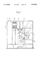
- FIG. 1 is a diagrammatic view of a coffee machine with the individual components
- FIG. 2 is a partial cross-sectional drawing of the brewing device of the coffee machine in the rinsing position
- FIG. 3 is a partial cross-sectional view of the brewing device of the coffee machine in the cleaning position
- FIG. 4 is a partial cross-sectional view of the brewing device of the coffee machine in the flooded position
- FIG. 5 is a top view of the brewing chamber depicting rinsing and cleaning channels.
- the coffee machine 1 includes a housing 2 with the components disposed therein, namely as the central module.
- the machine includes a brewing device 3, a coffee bean container with mill work 4, a funnel 5 disposed thereunder for the ground coffee powder, a water tank 6, an instantaneous water heater 7, a pump 8, a coffee outlet 9, a container for coffee grounds and a collection pan 11 for the cleaning water.
- a service module 12 is also provided for controlling of the operational processes of the coffee machine.
- the aim of the cleaning process is the cleaning of the parts of the coffee machine soiled by coffee and by coffee grounds, most of which parts are disposed in the brewing device 3. Concerning the method of operation of the brewing device 3, reference is made to U.S. Pat. No. 5,259,296.
- Both the brewing water and the cleaning water are conducted from the water tank 6 through the pump 8 through the instantaneous water heater 7 to the water supply connection 13 on the brewing cylinder 14.
- water coming from the same water tank 6 is used as for preparation of the coffee.
- a first extension piece 15 of the brewing cylinder covers the lower output end of the funnel 5 in the position of the brewing cylinder shown.
- a second extension piece 16 on the brewing cylinder 14 serves as the chute for conveying the coffee grounds expelled from the brewing cylinder into the grounds container 10.
- the filled coffee grounds container 10 is emptied each time prior to the cleaning procedure.
- the rinsing position is shown in FIG. 2.
- the rinse water entering through the water supply connection 13 passes through a channel 17 in the outer ring area 18 of the ejection piston 19.
- the rinse water then passes through the sieve plate 20 into the outlet pipe 21, through the discharge line 22 and the coffee outlet 9, and then through the discharge pipes 36 to an external water tank 23.
- a rinsing takes place of the parts subjected to soiling, namely the ejection piston 19, the lower area of the brewing cylinder, i.e. the brewing chamber, the sieve plate 20 on the brewing piston 26, the outlet pipe 21, the discharge line 22, and the coffee outlet 9.
- the rinse water in this phase takes the route of the brewing water or brewed coffee, respectively.
- rinsing channels 25, for example eight Disposed in the wall 24 of the brewing cylinder 14 are several rinsing channels 25, for example eight, which in the first cleaning phase described here, the rinse phase, are covered over by the brewing piston 26, however, as is also the case during coffee brewing.
- a projection 28 running on a slant, and a projection 29 joined thereto, parallel to the guide for the brewing piston. The function of this projection 28 will be described in the second phase of the cleaning process.
- Pivotably disposed about fulcrum 30 is a lever 31 for horizontal swinging of the brewing cylinder 14.
- Ejection means are also provided in the area of this lever to move the ejection piston 19 upward in brewing cylinder 14.
- the route taken by the rinse water is indicated by arrows.
- FIG. 3 shows the brewing device in the cleaning position, which represents the second phase of the cleaning process.
- the cleaning water flows again through the water supply connection 13 and through the channel 17 in the ring area 18 of the ejection piston 19, and from there through the rinsing channels 25 in the wall 24 of the brewing cylinder 14 into the area outside the brewing cylinder.
- the brewing piston 26 frees the channels 25 in the lower area, with the channels formed as grooves in the inner wall 34 of the brewing cylinder.
- the cleaning water sprays on the slanted projection 28 of the guide 27 for the brewing piston and from there reaches the second extension piece 16 and cleans it of coffee grounds.
- the cleaning water coming out through the rinsing channels sprays inbetween the angular part 32 of the guide 27 for the brewing piston 26 and the first extension piece 15 of the brewing cylinder. Moreover water is sprayed upwards inbetween the inner wall of the guide 27 for the brewing piston and the brewing piston 26, as indicated in FIG. 3. As a result of the jet effect of the water coming out through the rinsing channels, particles of coffee grounds are washed away.
- the rinsing channels or grooves 25 can be disposed asymmetrically and can be designed differing from one another in size. The route of the rinse water is again indicated by arrows.
- the flooded state, the third phase of the cleaning process, is shown in FIG. 4.
- the brewing piston 26 is higher up, in a retracted position, than is the case in the phases shown in FIGS. 2 and 3.
- the brewing cylinder 14 is filled to the maximum possible water level via the water supply connection 13. Owing to the slanted position of the brewing cylinder, the surface of the water 33 runs on a slant with respect to the wall 24 of the brewing cylinder.
- the ejection piston 19 is pushed upward in the direction of arrow A and the brewing piston 26 in the direction of arrow B somewhat upward into the position shown so that the water flows around about, up and out of the brewing cylinder 14.
- the water flows down in the direction of the arrow between the projection 28 and the second extension piece 16 and between the lower angular piece 32 of guide 27 for the brewing piston and the first extension piece 15 in the direction of the funnel 5.
- the overflowing water takes particles of coffee grounds along with it.
- the various cleaning phases are triggered by control electronics disposed in the coffee machine which are put in operation by means of the service module 12.
- FIG. 5 is a top view of the brewing chamber 14 with the first and second extension pieces 15 and 16 shown.
- the rinsing channels are designed as grooves 25 disposed in the inner wall 34 of the brewing cylinder.
- the rinsing channels shown in FIG. 5 are disposed symmetrically; they could also be disposed asymmetrically, however.
- a chemical and/or biological cleaning can take place as a further, fourth cleaning phase.
- the brewing cylinder 14 is swung into the grinding position under funnel 5, a cleaning agent in tablet, powder or liquid form being introduced into the powder shaft. Afterwards the brewing cylinder is swung back into its rinsing position as shown in to FIG. 2.
- the cleaning agent takes effect for some time. The rinsing process is preferably repeated several times.
- the cleaning agent can also be brought in from a cleaning agent tank, not shown, from a water tank or from a cartridge, via valve-pump-instantaneous water heater-brewing cylinder.
- any possible residue of the cleaning agent is expelled by the ejection piston 19 in a fifth phase.
- the brewing piston is moved upward thereby into the position shown in FIG. 4.
- a sixth phase which is rinsing.
- the brewing device remains in the position shown in FIG. 2; the pump pumps water through the system and rinses away any cleaning agent.
- the brewing cylinder is moved into the grinding position. At the same time the user is reminded to empty the collection pan 11.
- the water for cleaning is taken from a fresh water supply source connected to the coffee machine.
- the individual phases or steps, respectively, of the cleaning procedure can also be carried out in a different order, it being possible to omit or repeat one or several phases.
Abstract
Description
Claims (13)
Applications Claiming Priority (2)
| Application Number | Priority Date | Filing Date | Title |
|---|---|---|---|
| CH375293 | 1993-12-15 | ||
| CH3752/93 | 1993-12-15 |
Publications (1)
| Publication Number | Publication Date |
|---|---|
| US5551988A true US5551988A (en) | 1996-09-03 |
Family
ID=4262734
Family Applications (1)
| Application Number | Title | Priority Date | Filing Date |
|---|---|---|---|
| US08/354,125 Expired - Lifetime US5551988A (en) | 1993-12-15 | 1994-12-06 | Method and apparatus for cleaning a brewing device, especially of a coffee machine |
Country Status (6)
| Country | Link |
|---|---|
| US (1) | US5551988A (en) |
| EP (1) | EP0658330B1 (en) |
| JP (1) | JP2802236B2 (en) |
| AT (1) | ATE165224T1 (en) |
| DE (1) | DE59405783D1 (en) |
| ES (1) | ES2118354T3 (en) |
Cited By (17)
| Publication number | Priority date | Publication date | Assignee | Title |
|---|---|---|---|---|
| US6101923A (en) * | 1997-03-13 | 2000-08-15 | Egro Ag | Automatic coffee maker |
| US20040011384A1 (en) * | 2002-07-19 | 2004-01-22 | Peter Jager | Unit for detecting an addition of a cleaning agent in a beverage dispenser |
| WO2009022364A2 (en) | 2007-08-10 | 2009-02-19 | Saeco Ipr Limited | Brewing unit for preparation of beverages, and machine comprising said brewing unit |
| US20100058932A1 (en) * | 2006-12-21 | 2010-03-11 | BSH Bosch und Siemens Hausgeräte GmbH | Holder for a service function object |
| US20100300299A1 (en) * | 2007-08-29 | 2010-12-02 | Nestec S.A. | Dispensing device for preparing and dispensing food and/or nutritional composition |
| US20110041697A1 (en) * | 2008-02-17 | 2011-02-24 | Egro Coffee Systems Ag | Brewing unit for a coffee maker |
| US20120037007A1 (en) * | 2009-04-23 | 2012-02-16 | Jean-Paul In-Albon | Apparatus for producing coffee or other beverages |
| US20140000657A1 (en) * | 2008-04-07 | 2014-01-02 | Nestec S.A. | Beverage preparation device with in-line scale removal system and descaling method using such system |
| US20150257586A1 (en) * | 2014-03-11 | 2015-09-17 | Starbucks Corporation Dba Starbucks Coffee Company | Single-serve beverage production machine |
| US9439532B2 (en) | 2014-03-11 | 2016-09-13 | Starbucks Corporation | Beverage production machines with multi-chambered basket units |
| US9504348B2 (en) | 2014-03-11 | 2016-11-29 | Starbucks Corporation | Cartridge ejection systems and methods for single-serve beverage production machines |
| US20170020328A1 (en) * | 2010-11-11 | 2017-01-26 | Nestec S.A. | Capsule, beverage production machine and system for the preparation of a nutritional product |
| US9968217B2 (en) | 2015-06-16 | 2018-05-15 | Starbucks Corporation | Beverage preparation systems with brew chamber securing mechanisms |
| US10342377B2 (en) | 2015-06-16 | 2019-07-09 | Starbucks Corporation | Beverage preparation systems with adaptable brew chambers |
| US10602874B2 (en) | 2015-06-16 | 2020-03-31 | Starbucks Corporation Dba Starbucks Coffee Company | Beverage preparation systems with brew chamber access mechanisms |
| WO2023110972A1 (en) * | 2021-12-16 | 2023-06-22 | Eversys S.A. | Device and method for producing a solution from an active substance and a solvent and for supplying the solution to a drinks preparation machine |
| WO2023110233A1 (en) * | 2021-12-16 | 2023-06-22 | Eversys S.A. | Cleaning device for a beverage preparation machine, and method for cleaning a beverage preparation machine |
Families Citing this family (12)
| Publication number | Priority date | Publication date | Assignee | Title |
|---|---|---|---|---|
| NL1010554C2 (en) * | 1998-10-07 | 2000-04-10 | Bravilor Holding Bv | Device for preparing a drink. |
| DE69920230T2 (en) * | 1999-10-28 | 2005-04-28 | Société des Produits Nestlé S.A. | Ejector for cartridge |
| ATE346528T1 (en) * | 2002-08-29 | 2006-12-15 | Jura Elektroapparate Ag | COFFEE MACHINE HAVING A HAND-OPERATED SPECIAL COFFEE INLET COVER AND METHOD FOR MONITORING THE POSITION OF SUCH COVER |
| DE202007001114U1 (en) * | 2007-01-25 | 2008-05-29 | Melitta Haushaltsprodukte Gmbh & Co Kommanditgesellschaft | Machine for making brewed beverages |
| ITBO20070302A1 (en) * | 2007-04-24 | 2008-10-25 | Gino Rapparini | IMPROVEMENT OF MACHINES TO OBTAIN EXPRESS TYPE OF INFUSIONS |
| DE102008003733B4 (en) * | 2008-01-10 | 2022-12-01 | Franke Kaffeemaschinen Ag | Cleaning module, device and method for cleaning machines for the production of liquid foodstuffs |
| DE102011110793A1 (en) * | 2011-08-22 | 2013-02-28 | Franke Kaffeemaschinen Ag | Coffee machine and brewing group for a coffee machine |
| EP2702908A1 (en) * | 2012-08-30 | 2014-03-05 | Jura Elektroapparate AG | Device for providing liquid for a drinks machine and use of same |
| EP3264951B1 (en) | 2015-03-04 | 2019-01-02 | Arçelik Anonim Sirketi | A coffee machine wherein the brewing chamber is cleaned |
| JP6974829B2 (en) * | 2017-08-07 | 2021-12-01 | 株式会社Tree Field | Extractor |
| JP7187075B2 (en) * | 2017-08-07 | 2022-12-12 | 株式会社大都技研 | extractor |
| IT201800006831A1 (en) * | 2018-06-29 | 2019-12-29 | Device for conveying at least one powdered ingredient, preferably coffee powder. |
Citations (6)
| Publication number | Priority date | Publication date | Assignee | Title |
|---|---|---|---|---|
| US3038492A (en) * | 1957-05-31 | 1962-06-12 | Barmart | Automatic coffee brewer |
| US3496861A (en) * | 1968-08-05 | 1970-02-24 | Melikian Inc Rudd | Device for disposing of spent coffee grounds |
| US4305328A (en) * | 1979-08-29 | 1981-12-15 | Umc Industries, Inc. | Coffee vendor |
| EP0173651A1 (en) * | 1984-07-11 | 1986-03-05 | Nuova Faema S.p.A. | A device for producing a hot milk cream from cold milk |
| US5303638A (en) * | 1993-02-26 | 1994-04-19 | Green Joseph H | Rodless piston and cylinder assembly for a reciprocating carriage |
| US5333537A (en) * | 1991-07-30 | 1994-08-02 | Sintra Holding Ag | Device for ejection of ground coffee pressed into a cake from a brewing apparatus of a coffee machine |
Family Cites Families (2)
| Publication number | Priority date | Publication date | Assignee | Title |
|---|---|---|---|---|
| DE3316157A1 (en) * | 1983-05-03 | 1984-11-08 | Württembergische Metallwarenfabrik AG, 7340 Geislingen | Brewing device for an automatically operating coffee-making machine |
| CH665945A5 (en) * | 1984-12-14 | 1988-06-30 | Cafag Ag | Automatic coffee making machine - incorporates cleaning fluid container connected by water inlet valve to coffee making compartment |
-
1994
- 1994-12-06 US US08/354,125 patent/US5551988A/en not_active Expired - Lifetime
- 1994-12-14 JP JP6310944A patent/JP2802236B2/en not_active Expired - Fee Related
- 1994-12-14 AT AT94810729T patent/ATE165224T1/en active
- 1994-12-14 ES ES94810729T patent/ES2118354T3/en not_active Expired - Lifetime
- 1994-12-14 EP EP94810729A patent/EP0658330B1/en not_active Expired - Lifetime
- 1994-12-14 DE DE59405783T patent/DE59405783D1/en not_active Expired - Lifetime
Patent Citations (6)
| Publication number | Priority date | Publication date | Assignee | Title |
|---|---|---|---|---|
| US3038492A (en) * | 1957-05-31 | 1962-06-12 | Barmart | Automatic coffee brewer |
| US3496861A (en) * | 1968-08-05 | 1970-02-24 | Melikian Inc Rudd | Device for disposing of spent coffee grounds |
| US4305328A (en) * | 1979-08-29 | 1981-12-15 | Umc Industries, Inc. | Coffee vendor |
| EP0173651A1 (en) * | 1984-07-11 | 1986-03-05 | Nuova Faema S.p.A. | A device for producing a hot milk cream from cold milk |
| US5333537A (en) * | 1991-07-30 | 1994-08-02 | Sintra Holding Ag | Device for ejection of ground coffee pressed into a cake from a brewing apparatus of a coffee machine |
| US5303638A (en) * | 1993-02-26 | 1994-04-19 | Green Joseph H | Rodless piston and cylinder assembly for a reciprocating carriage |
Cited By (27)
| Publication number | Priority date | Publication date | Assignee | Title |
|---|---|---|---|---|
| US6101923A (en) * | 1997-03-13 | 2000-08-15 | Egro Ag | Automatic coffee maker |
| US20040011384A1 (en) * | 2002-07-19 | 2004-01-22 | Peter Jager | Unit for detecting an addition of a cleaning agent in a beverage dispenser |
| US7017595B2 (en) * | 2002-07-19 | 2006-03-28 | Wmf Wuerttembergische Metallwarenfabrik Ab | Unit for detecting an addition of a cleaning agent in a beverage dispenser |
| US20100058932A1 (en) * | 2006-12-21 | 2010-03-11 | BSH Bosch und Siemens Hausgeräte GmbH | Holder for a service function object |
| US9386879B2 (en) * | 2006-12-21 | 2016-07-12 | Bsh Hausgeraete Gmbh | Holder for a service function object |
| WO2009022364A2 (en) | 2007-08-10 | 2009-02-19 | Saeco Ipr Limited | Brewing unit for preparation of beverages, and machine comprising said brewing unit |
| US9364115B2 (en) | 2007-08-10 | 2016-06-14 | Koninklijke Philips N.V. | Brewing unit for preparation of beverages, and machine comprising said brewing unit |
| US20100300299A1 (en) * | 2007-08-29 | 2010-12-02 | Nestec S.A. | Dispensing device for preparing and dispensing food and/or nutritional composition |
| CN101795605B (en) * | 2007-08-29 | 2013-01-02 | 雀巢产品技术援助有限公司 | Dispensing device for preparing and dispensing food and/or nutritional composition |
| US8468934B2 (en) * | 2007-08-29 | 2013-06-25 | Nestec S.A. | Dispensing device for preparing and dispensing food and/or nutritional composition |
| US8770092B2 (en) | 2008-02-17 | 2014-07-08 | Egro Suisse Ag | Brewing unit for a coffee machine |
| US20110041697A1 (en) * | 2008-02-17 | 2011-02-24 | Egro Coffee Systems Ag | Brewing unit for a coffee maker |
| CN101951821B (en) * | 2008-02-17 | 2014-01-22 | 埃格罗咖啡系统公司 | Brewing unit for a coffee maker |
| US20140000657A1 (en) * | 2008-04-07 | 2014-01-02 | Nestec S.A. | Beverage preparation device with in-line scale removal system and descaling method using such system |
| US8857316B2 (en) * | 2009-04-23 | 2014-10-14 | Jean-Paul In-Albon | Apparatus for producing coffee or other beverages |
| US20120037007A1 (en) * | 2009-04-23 | 2012-02-16 | Jean-Paul In-Albon | Apparatus for producing coffee or other beverages |
| US20170020328A1 (en) * | 2010-11-11 | 2017-01-26 | Nestec S.A. | Capsule, beverage production machine and system for the preparation of a nutritional product |
| US10070751B2 (en) * | 2010-11-11 | 2018-09-11 | Nestec S.A. | Capsule, beverage production machine and system for the preparation of a nutritional product |
| US9439532B2 (en) | 2014-03-11 | 2016-09-13 | Starbucks Corporation | Beverage production machines with multi-chambered basket units |
| US9504348B2 (en) | 2014-03-11 | 2016-11-29 | Starbucks Corporation | Cartridge ejection systems and methods for single-serve beverage production machines |
| US20150257586A1 (en) * | 2014-03-11 | 2015-09-17 | Starbucks Corporation Dba Starbucks Coffee Company | Single-serve beverage production machine |
| US9999315B2 (en) | 2014-03-11 | 2018-06-19 | Starbucks Corporation | Beverage production methods with multi chambered basket units |
| US9968217B2 (en) | 2015-06-16 | 2018-05-15 | Starbucks Corporation | Beverage preparation systems with brew chamber securing mechanisms |
| US10342377B2 (en) | 2015-06-16 | 2019-07-09 | Starbucks Corporation | Beverage preparation systems with adaptable brew chambers |
| US10602874B2 (en) | 2015-06-16 | 2020-03-31 | Starbucks Corporation Dba Starbucks Coffee Company | Beverage preparation systems with brew chamber access mechanisms |
| WO2023110972A1 (en) * | 2021-12-16 | 2023-06-22 | Eversys S.A. | Device and method for producing a solution from an active substance and a solvent and for supplying the solution to a drinks preparation machine |
| WO2023110233A1 (en) * | 2021-12-16 | 2023-06-22 | Eversys S.A. | Cleaning device for a beverage preparation machine, and method for cleaning a beverage preparation machine |
Also Published As
| Publication number | Publication date |
|---|---|
| EP0658330A1 (en) | 1995-06-21 |
| JP2802236B2 (en) | 1998-09-24 |
| ES2118354T3 (en) | 1998-09-16 |
| ATE165224T1 (en) | 1998-05-15 |
| EP0658330B1 (en) | 1998-04-22 |
| DE59405783D1 (en) | 1998-05-28 |
| JPH07265213A (en) | 1995-10-17 |
Similar Documents
| Publication | Publication Date | Title |
|---|---|---|
| US5551988A (en) | Method and apparatus for cleaning a brewing device, especially of a coffee machine | |
| CN108463146B (en) | Espresso coffee machine with system for cleaning the coffee dispensing system | |
| EP0169847B1 (en) | Method in a cleaning machine and a cleaning machine for working the method | |
| KR102101298B1 (en) | Apparatus, systems, and methods for brewing a beverage | |
| US5297472A (en) | Beverage extraction device | |
| WO1995011613A3 (en) | Automatic espresso and cappuccino machine | |
| CN100423674C (en) | Beverage brewing device | |
| OA12261A (en) | Device for extraction a substance. | |
| JPH07114670A (en) | Extraction and distribution machine of drink | |
| CA2105220A1 (en) | Coffee Brewer Method and Apparatus | |
| US10842311B2 (en) | Automated coffee and tea maker and automated pressure brewer | |
| CN113597271B (en) | Ultrasonic cleaning device for espresso coffee machine and espresso coffee machine comprising such a cleaning device | |
| JPH0910112A (en) | Raw bean coffee solution extractor for vending machine | |
| CN211299534U (en) | Feeding device for automatic quantifying and conveying of beverage raw materials | |
| GB1575806A (en) | Beverage dispensing machines | |
| JPH1118951A (en) | Bevarage supply device | |
| US3429253A (en) | Apparatus for hot beverage brewing | |
| US2996975A (en) | Rotary beverage-brewing apparatus | |
| US20210369045A1 (en) | Hot beverage preparer with a drainage device | |
| CN212074486U (en) | Easily wash semi-solid state seasoning liquid filling machine | |
| JPH0681610B2 (en) | Washing water supply method and equipment | |
| JP2549360B2 (en) | Rice washing equipment | |
| WO2022214982A1 (en) | System for cleaning milk ducts for a machine for preparing beverages | |
| JP2022059048A (en) | Cleaning method and cleaner | |
| JPH10334340A (en) | Drink supplier |
Legal Events
| Date | Code | Title | Description |
|---|---|---|---|
| AS | Assignment |
Owner name: JURA ELEKTROAPPARATE AG, SWITZERLAND Free format text: ASSIGNMENT OF ASSIGNORS INTEREST;ASSIGNORS:REYHANLOO, SHAHRYAR;HERMANN, MARKUS;ANLIKER, MARKUS;REEL/FRAME:007322/0498 Effective date: 19950124 |
|
| STCF | Information on status: patent grant |
Free format text: PATENTED CASE |
|
| FPAY | Fee payment |
Year of fee payment: 4 |
|
| FEPP | Fee payment procedure |
Free format text: PAT HOLDER NO LONGER CLAIMS SMALL ENTITY STATUS, ENTITY STATUS SET TO UNDISCOUNTED (ORIGINAL EVENT CODE: STOL); ENTITY STATUS OF PATENT OWNER: LARGE ENTITY |
|
| FPAY | Fee payment |
Year of fee payment: 8 |
|
| FPAY | Fee payment |
Year of fee payment: 12 |