US554635A - dela mar - Google Patents
dela mar Download PDFInfo
- Publication number
- US554635A US554635A US554635DA US554635A US 554635 A US554635 A US 554635A US 554635D A US554635D A US 554635DA US 554635 A US554635 A US 554635A
- Authority
- US
- United States
- Prior art keywords
- shaft
- roller
- tobacco
- machine
- cigars
- Prior art date
- Legal status (The legal status is an assumption and is not a legal conclusion. Google has not performed a legal analysis and makes no representation as to the accuracy of the status listed.)
- Expired - Lifetime
Links
- 239000000969 carrier Substances 0.000 description 36
- 241000208125 Nicotiana Species 0.000 description 34
- 235000002637 Nicotiana tabacum Nutrition 0.000 description 34
- 235000019506 cigar Nutrition 0.000 description 26
- 239000000945 filler Substances 0.000 description 18
- 239000000463 material Substances 0.000 description 4
- 241001446467 Mama Species 0.000 description 2
- 241000124008 Mammalia Species 0.000 description 2
- 238000005520 cutting process Methods 0.000 description 2
- 229920000591 gum Polymers 0.000 description 2
- 238000004519 manufacturing process Methods 0.000 description 2
- 238000003825 pressing Methods 0.000 description 2
- 230000036633 rest Effects 0.000 description 2
- 238000005096 rolling process Methods 0.000 description 2
Images


Classifications
-
- A—HUMAN NECESSITIES
- A24—TOBACCO; CIGARS; CIGARETTES; SIMULATED SMOKING DEVICES; SMOKERS' REQUISITES
- A24C—MACHINES FOR MAKING CIGARS OR CIGARETTES
- A24C5/00—Making cigarettes; Making tipping materials for, or attaching filters or mouthpieces to, cigars or cigarettes
- A24C5/14—Machines of the continuous-rod type
- A24C5/18—Forming the rod
- A24C5/1871—Devices for regulating the tobacco quantity
Definitions
- This invention relates more particularly to feeding and automatic cutting mechanism in machines for forming fillers for cigars, the object being to provide a simple and efficient machine for this purpose.
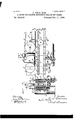
- Figure 1 is a front elevation of a machine embodying my invention.
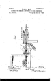
- Fig. 2 is a rear elevation of feed mechanism employed.
- Fig. 3 is a plan view thereof.
- Fig. 4 is an enlarged longitudinal section through the center of the feed mechanism.
- Fig. 5 is a transverse section on the line 5 5 of Fig. 4.
- Fig. 6 is an enlarged plan view of cutters and portions of other parts.
- A is a band or power wheel loosely mounted upon but adapted to rotate a main shaft a when a certain clutch mechanism is thrown into engagement and operate the machine.
- the main shaft a has a bearing at one end in a pillow-block a and at the other end in the main frame of the machine.
- a pinion a is rigidly mounted on the shaft a and has on or adjacent to it one member of a clutch a
- the other member of the clutch a is attached to the pulley A and is movable with said pulley into engagement with the other member of the clutch by means of a lever A bifurcated at its upper end and engaging in an annular groove of the movable section of the clutch.
- the lever A At its lower end the lever A is attached to a rock-shaft a having bearings in the main frame, and is provided with a treadle-lever a. Obviously by a downward movement of the treadle a the pulley A and its clutch-section will be moved longitudinally on the shaft a and into engagement with the clutch-section on the pinion a The pinion a meshes with a gear-wheel A secured to a shaft a As a means for unlocking the clutch-sections when the lever a is released by the foot of the operator, I employ a yielding arm a which is secured at its lower end to the rockshaft a and projecting at its free end into the path of a lug a on the gear-wheel A.
- This gear-wheel is a gear-wheel mounted on the shaft a This gear-wheel is toothed about half its circumference to impart a complete revolution to a pinion b at a partial revolution of the wheel B.
- the F F is a way or chute through which tobacco is conveyed to the formers.
- the tobacco is transferred by an attendant from the table or box 0 to' carriers F F.
- the carriers F F are in the form of endless bands running in the way F, one band, F extending around rollers ff, one of which is arranged adjacent to and in line with an entrance f to the presserdies, and the other, f, has journal-bearings in hangers at the outer end of the way F.
- the carrier F is shorter than the carrier F and is arranged below the same, and extends around rollers f f 3 j ournaled in hangers depending from the way F.
- the short carrier F has at convenient points arms extending from it at substantially right angles to the width of the carrier.
- These arms are designed to embrace the charge of tobacco at the sides.
- the roller f over which the carrier F extends is at some distance from the entrance f to the dies, so that there is considerable space in which the arms do not aid in the carrying of tobacco.
- To carry the tobacco along this space I employ an endless presser-band G.
- This band G extends around rollers g 9, one of which has j ournal-bearings in blocks which are vertically adjustable in ways 9
- the carrier F and the presserband G are serrated or provided with transverse ratchet-shaped teeth 0, which may be of rubber or similar material. These toothlike projections serve to grip the tobacco and more eifectually carry it along.
- the several rollers over which the carriers and presser-band extend are preferably'covered on their bearing-surface with some rough material, 0, such as fish-skin.
- the roller 9 has its shaft bearing in theouter ends of bars g", the other ends of which have a swinging connection with the journals of the roller g.
- a weight g at theend of a rod g suspended from one of the bars 9, serves to hold the band G tightly against the upper side of the tobacco.
- the serrated carrier F is driven by a rackbar [15 reciprocated vertically by the driving mechanism and engaging with a toothed wheel having a pawl-and-ratchet connection (not shown) with the shaft of the roller f, and the presser-band Gr is driven through the medium of a band k, a roller 10 on the shaft of the roller f a roller on the shaft of the roller f, and intermediate mechanism, as described in my Patent No. 461,072, of October 13, 1891, and Patent No. 4983M, of June 6, 1893, before referred to.
- the top cutters here shown consist of rotary cutter-disks D D, having their edges overlapped above the way F.
- Each cutter-disk is mounted on a vertical shaft (Z, having bearings in sleeves d adjustably supported by thumb-screws (Z in boxes cl on opposite sides of the way F.
- the cutter-disks D D are driven from the main shaft a by means of a band (1 rotating a shaft (1 which has a bevelgear (I engaging with a bevel-gear on the shaft of the cutter-disk D.
- the shaft of the cutter-disk D has a gear-wheel d meshing witha gear-wheel cl on theshaft of the cutter-disk D.
- the disks areadjustable vertically.
- the shaft d of the cutter D extends through the bevelgear 0 and a set-screw is employed to secure the gear 0 to the shaft. This allows the ad j ustment of the vertical shaft without chang ing the relative positions of the gears c d.
- a rubber washer (Z is mounted on the shaft of the disk D between the lower end of the sleeve (Z and the wheel (1 and serves by its slight expansion to draw the shaft of the cutter D downward, and thus press the cutters together.
- the tobacco is pressed downward in the way F before it reaches the top cutters by means of a roller E, having its journals movable upward and downward in bearings 6.
- Each link 6 extends downward from a journal of the roller E and has connection with a fulcrumed lever 6 provided with an adjustable weight a
- This Weight is adjustable in this manner is to give the tobacco either a compact or loose consistency according to the requirement of the bunch desired, an essential point in the manufacture of cigars.
- a shoe E arranged between the roller E and the cutter-disks D D serves to retain the filler in its compressed condition in its movement between the roller E and the cutterdisks.
- This shoe has an oscillating movement and is movable vertically with the vertical movement of the wheel E, and it rests at all times on the top of the tobacco. Itis attached to an arm h pivoted on a journal of the roller E and a forwardly-extending arm h provided with a weight 7L which serves to hold the shoe with pressure on the tobacco.
- the surplus tobacco, or that cut off the top of the tobacco, is directed by means of a curved deflector II, having a guard II on its top, to the box 0 and mixed with the tobacco therein automatically,therebysavin g rehandling.
Landscapes
- Manufacturing Of Cigar And Cigarette Tobacco (AREA)
Description
, mammal.) 4 sheetssheet 1.
MACHINE FOR-FORMING CONTINUOUS I'ILLERS EOE CIGARS.
N0 554 ,6'35. Patented Feb. 11, 1896.
Queen/tor,
With mama ANDREW isRMlAM. PMOTO-UTNQWASMNGTON. 0.0
(No ModeLj 4 SheetsSheet 2. J. DELA MAR.
MACHINE FOR FORMING CONTINUOUS PILLERS FOR CIGARS.
No. 554,635. Patented Feb; 11,1896.
- (No Model.) 4-Sheets-She'et 3 J. DELA MAR. MAGHINEPOR FORMING CONTINUOUS FILLBES FOR GIGARS.
Patented Feb. 11
%4' Gum n wx m (No Model.) 4 Sheets-Sheet 4. J. DELA MAR.
MACHINE FOR FORMING CONTINUOUS FILLERS FOR CIGARS.-
Patented Feb. 1 1, 1896.
5144mm 22 7a) a mane/1 M M N f UNITED STATES PATENT OFFIC JOSEPH DELA MAR, OF NEW YORK, N. Y., ASSIGNOR TO THE CHAMPION TOBACCO MACHINE COMPANY, OF SAME PLACE.
MAOHENE FOR FORMING CONTINUOUS FILLERS FOR CIGARS.
SPECIFICATION forming part of Letters Patent No. 554,635, dated February 11, 1896.
Application filed April 26, 1892. $eria1No. 430,807. (No model.)
To all whom it may concern.-
Be it known that I, JOSEPH DELA MAR, of the city, county, and State of New York, have invented a certain new and useful Improvement in Machines for Forming Continuous Fillers for Cigars, of which the following is a specification.
This invention relates more particularly to feeding and automatic cutting mechanism in machines for forming fillers for cigars, the object being to provide a simple and efficient machine for this purpose.
In the accompanying drawings, Figure 1 is a front elevation of a machine embodying my invention. Fig. 2 is a rear elevation of feed mechanism employed. Fig. 3 is a plan view thereof. Fig. 4 is an enlarged longitudinal section through the center of the feed mechanism. Fig. 5 is a transverse section on the line 5 5 of Fig. 4. Fig. 6 is an enlarged plan view of cutters and portions of other parts.
I will first briefly describe certain parts of the machine, which, however, are fully described in my Patent No. 461,072, of October 13, 1891, and my Patent No. 498,844, of June A designates a table supported by legs A, which have suitable cross-bars for supporting rotary parts of the machine.
A is a band or power wheel loosely mounted upon but adapted to rotate a main shaft a when a certain clutch mechanism is thrown into engagement and operate the machine. The main shaft a has a bearing at one end in a pillow-block a and at the other end in the main frame of the machine. A pinion a is rigidly mounted on the shaft a and has on or adjacent to it one member of a clutch a The other member of the clutch a is attached to the pulley A and is movable with said pulley into engagement with the other member of the clutch by means of a lever A bifurcated at its upper end and engaging in an annular groove of the movable section of the clutch. At its lower end the lever A is attached to a rock-shaft a having bearings in the main frame, and is provided with a treadle-lever a. Obviously by a downward movement of the treadle a the pulley A and its clutch-section will be moved longitudinally on the shaft a and into engagement with the clutch-section on the pinion a The pinion a meshes with a gear-wheel A secured to a shaft a As a means for unlocking the clutch-sections when the lever a is released by the foot of the operator, I employ a yielding arm a which is secured at its lower end to the rockshaft a and projecting at its free end into the path of a lug a on the gear-wheel A. As long as the operators foot holds down the lever to" the arm a will yield and pass over the lug a but upon releasing the lever a the lug will move the arm a and through it the rock-shaft a and clutch-arm A This clutch-operating mechanism is fully shown and described in my Patent No. 461,072, of October 13, 1891.
B is a gear-wheel mounted on the shaft a This gear-wheel is toothed about half its circumference to impart a complete revolution to a pinion b at a partial revolution of the wheel B.
Having sufficiently described the driving mechanism when taken in connection with mypatent of October 13, 1891, I will now describe the parts relating more particularly to my present invention, premising, however, that it is to be understood that the machine is provided with filler-pressing dies and rolling mechanism.
F is a way or chute through which tobacco is conveyed to the formers. The tobacco is transferred by an attendant from the table or box 0 to' carriers F F. The carriers F F are in the form of endless bands running in the way F, one band, F extending around rollers ff, one of which is arranged adjacent to and in line with an entrance f to the presserdies, and the other, f, has journal-bearings in hangers at the outer end of the way F. The carrier F is shorter than the carrier F and is arranged below the same, and extends around rollers f f 3 j ournaled in hangers depending from the way F. The short carrier F has at convenient points arms extending from it at substantially right angles to the width of the carrier. These arms are designed to embrace the charge of tobacco at the sides. The roller f over which the carrier F extends is at some distance from the entrance f to the dies, so that there is considerable space in which the arms do not aid in the carrying of tobacco. To carry the tobacco along this space I employ an endless presser-band G. This band G extends around rollers g 9, one of which has j ournal-bearings in blocks which are vertically adjustable in ways 9 The carrier F and the presserband G are serrated or provided with transverse ratchet-shaped teeth 0, which may be of rubber or similar material. These toothlike projections serve to grip the tobacco and more eifectually carry it along.
The several rollers over which the carriers and presser-band extend are preferably'covered on their bearing-surface with some rough material, 0, such as fish-skin.
The roller 9 has its shaft bearing in theouter ends of bars g", the other ends of which have a swinging connection with the journals of the roller g. A weight g at theend of a rod g suspended from one of the bars 9, serves to hold the band G tightly against the upper side of the tobacco.
The serrated carrier F is driven by a rackbar [15 reciprocated vertically by the driving mechanism and engaging with a toothed wheel having a pawl-and-ratchet connection (not shown) with the shaft of the roller f, and the presser-band Gr is driven through the medium of a band k, a roller 10 on the shaft of the roller f a roller on the shaft of the roller f, and intermediate mechanism, as described in my Patent No. 461,072, of October 13, 1891, and Patent No. 4983M, of June 6, 1893, before referred to. A quantity of tobacco having been placed on the carrier F by an operator, the said tobacco is carried forward, but before it reaches the presserband G the top of the charge is trinnned off, so that only the required charge for one cigar is fed into the dies at one time.
The top cutters here shown consist of rotary cutter-disks D D, having their edges overlapped above the way F. Each cutter-disk is mounted on a vertical shaft (Z, having bearings in sleeves d adjustably supported by thumb-screws (Z in boxes cl on opposite sides of the way F. The cutter-disks D D are driven from the main shaft a by means of a band (1 rotating a shaft (1 which has a bevelgear (I engaging with a bevel-gear on the shaft of the cutter-disk D. The shaft of the cutter-disk D has a gear-wheel d meshing witha gear-wheel cl on theshaft of the cutter-disk D. The disks areadjustable vertically. This may be done by adjusting the sleevesd within the boxes CZ. The shaft d of the cutter D extends through the bevelgear 0 and a set-screw is employed to secure the gear 0 to the shaft. This allows the ad j ustment of the vertical shaft without chang ing the relative positions of the gears c d. A rubber washer (Z is mounted on the shaft of the disk D between the lower end of the sleeve (Z and the wheel (1 and serves by its slight expansion to draw the shaft of the cutter D downward, and thus press the cutters together.
The tobacco is pressed downward in the way F before it reaches the top cutters by means of a roller E, having its journals movable upward and downward in bearings 6. Each link 6 extends downward from a journal of the roller E and has connection with a fulcrumed lever 6 provided with an adjustable weight a The reason this Weight is adjustable in this manner is to give the tobacco either a compact or loose consistency according to the requirement of the bunch desired, an essential point in the manufacture of cigars.
A shoe E arranged between the roller E and the cutter-disks D D serves to retain the filler in its compressed condition in its movement between the roller E and the cutterdisks. This shoehas an oscillating movement and is movable vertically with the vertical movement of the wheel E, and it rests at all times on the top of the tobacco. Itis attached to an arm h pivoted on a journal of the roller E and a forwardly-extending arm h provided with a weight 7L which serves to hold the shoe with pressure on the tobacco.
The surplus tobacco, or that cut off the top of the tobacco, is directed by means of a curved deflector II, having a guard II on its top, to the box 0 and mixed with the tobacco therein automatically,therebysavin g rehandling.
Having described my invention, what I 1. In a machine for forming a continuous filler for cigars the combination with a feedway and carriers of top cutters operating over said feedway, substantially as specified.
2. In a machine for forming a continuous filler for cigars the combination with a feedway and a carrier of rotary top cutters, substantially as specified.
3. In a machine for forming a continuous filler for cigars the combination with a feedway and carriers of vertically-adjustable r0- tary top cutters, substantially as specified.
4:. 111 a machine for forming a continuous filler for cigars the combination with a feed way and the carriers of the rotary'top cutters and an adj ustable pressenroller adjacent said top cutters, substantially asspecilied. v
5. In a machine for forming a continuous filler for cigars the combination with a feedway and carriers of the rotary top cutters, the
presser-roller and the presser-shoe between 'the cutters and said roller, substantially as specified. g g
6. In a machine for forming a continuous filler for cigars the combination with a feedway and carriers of rotary cutters over said feedway, a pressure-roller, means for regulatdeflector for deflecting the top cuttings into ing the pressure of said roller and a Weighted a receptacle, substantially as specified. pressure-shoe between the roller and cutters,
substantially as specified. JOSEPH DELA MAR. 5 7. In a machine for forming a continuous Witnesses:
filler for cigars the combination with a feed- W. L. BENNEM,
way and carriers of rotary top cutters, anda V. T. WILSON.
Publications (1)
| Publication Number | Publication Date |
|---|---|
| US554635A true US554635A (en) | 1896-02-11 |
Family
ID=2623373
Family Applications (1)
| Application Number | Title | Priority Date | Filing Date |
|---|---|---|---|
| US554635D Expired - Lifetime US554635A (en) | dela mar |
Country Status (1)
| Country | Link |
|---|---|
| US (1) | US554635A (en) |
Cited By (3)
| Publication number | Priority date | Publication date | Assignee | Title |
|---|---|---|---|---|
| US2660177A (en) * | 1948-02-17 | 1953-11-24 | Usines Deeoufle Sa | Automatic tobacco feeding cigarette machine |
| US2660178A (en) * | 1948-02-17 | 1953-11-24 | Usines Decoufle Sa | Formation of the roll of tobacco in cigarette-making machines |
| US3261366A (en) * | 1959-01-22 | 1966-07-19 | Hauni Werke Koerber & Co Kg | Apparatus for producing a tobacco rod |
-
0
- US US554635D patent/US554635A/en not_active Expired - Lifetime
Cited By (3)
| Publication number | Priority date | Publication date | Assignee | Title |
|---|---|---|---|---|
| US2660177A (en) * | 1948-02-17 | 1953-11-24 | Usines Deeoufle Sa | Automatic tobacco feeding cigarette machine |
| US2660178A (en) * | 1948-02-17 | 1953-11-24 | Usines Decoufle Sa | Formation of the roll of tobacco in cigarette-making machines |
| US3261366A (en) * | 1959-01-22 | 1966-07-19 | Hauni Werke Koerber & Co Kg | Apparatus for producing a tobacco rod |
Similar Documents
| Publication | Publication Date | Title |
|---|---|---|
| US554635A (en) | dela mar | |
| US448163A (en) | Machine | |
| US841216A (en) | Machine for making cigarettes. | |
| US919297A (en) | Tobacco-stripper. | |
| US466759A (en) | And euclid m | |
| US437987A (en) | John w | |
| US470269A (en) | Cigarette-machine | |
| US512150A (en) | Cigarette-machine | |
| US933239A (en) | Cigarette-machine. | |
| US662775A (en) | Cigarette-making machine. | |
| US417733A (en) | Bullets and shot | |
| US542974A (en) | Half to s | |
| US560483A (en) | Tobacco-cutting machine | |
| US806753A (en) | Fiber-cutting machine. | |
| US209808A (en) | Improvement in machines for rolling and cutting tobacco | |
| US902308A (en) | Hose-making machine. | |
| US410582A (en) | enoch | |
| US254969A (en) | Charles hemje | |
| US459115A (en) | Cigarette-cutter | |
| US263968A (en) | sacket | |
| US452011A (en) | Machine for breaking and making fillers for cigars | |
| US568981A (en) | Corn-husker and stalk-cutter | |
| US585253A (en) | Cigarette-machine | |
| US234183A (en) | Feed-cutter | |
| US255512A (en) | Half to joseph b |