US5539451A - Method and apparatus for channel spinning off a channel - Google Patents
Method and apparatus for channel spinning off a channel Download PDFInfo
- Publication number
- US5539451A US5539451A US08/364,628 US36462894A US5539451A US 5539451 A US5539451 A US 5539451A US 36462894 A US36462894 A US 36462894A US 5539451 A US5539451 A US 5539451A
- Authority
- US
- United States
- Prior art keywords
- program
- channel
- temporary channel
- temporary
- subscriber stations
- Prior art date
- Legal status (The legal status is an assumption and is not a legal conclusion. Google has not performed a legal analysis and makes no representation as to the accuracy of the status listed.)
- Expired - Lifetime
Links
Images


Classifications
-
- H—ELECTRICITY
- H04—ELECTRIC COMMUNICATION TECHNIQUE
- H04N—PICTORIAL COMMUNICATION, e.g. TELEVISION
- H04N21/00—Selective content distribution, e.g. interactive television or video on demand [VOD]
- H04N21/40—Client devices specifically adapted for the reception of or interaction with content, e.g. set-top-box [STB]; Operations thereof
- H04N21/43—Processing of content or additional data, e.g. demultiplexing additional data from a digital video stream; Elementary client operations, e.g. monitoring of home network or synchronising decoder's clock; Client middleware
- H04N21/442—Monitoring of processes or resources, e.g. detecting the failure of a recording device, monitoring the downstream bandwidth, the number of times a movie has been viewed, the storage space available from the internal hard disk
- H04N21/44213—Monitoring of end-user related data
- H04N21/44222—Analytics of user selections, e.g. selection of programs or purchase activity
-
- H—ELECTRICITY
- H04—ELECTRIC COMMUNICATION TECHNIQUE
- H04N—PICTORIAL COMMUNICATION, e.g. TELEVISION
- H04N21/00—Selective content distribution, e.g. interactive television or video on demand [VOD]
- H04N21/20—Servers specifically adapted for the distribution of content, e.g. VOD servers; Operations thereof
- H04N21/25—Management operations performed by the server for facilitating the content distribution or administrating data related to end-users or client devices, e.g. end-user or client device authentication, learning user preferences for recommending movies
- H04N21/258—Client or end-user data management, e.g. managing client capabilities, user preferences or demographics, processing of multiple end-users preferences to derive collaborative data
- H04N21/25866—Management of end-user data
- H04N21/25891—Management of end-user data being end-user preferences
-
- H—ELECTRICITY
- H04—ELECTRIC COMMUNICATION TECHNIQUE
- H04N—PICTORIAL COMMUNICATION, e.g. TELEVISION
- H04N21/00—Selective content distribution, e.g. interactive television or video on demand [VOD]
- H04N21/80—Generation or processing of content or additional data by content creator independently of the distribution process; Content per se
- H04N21/81—Monomedia components thereof
- H04N21/812—Monomedia components thereof involving advertisement data
-
- H—ELECTRICITY
- H04—ELECTRIC COMMUNICATION TECHNIQUE
- H04N—PICTORIAL COMMUNICATION, e.g. TELEVISION
- H04N21/00—Selective content distribution, e.g. interactive television or video on demand [VOD]
- H04N21/80—Generation or processing of content or additional data by content creator independently of the distribution process; Content per se
- H04N21/85—Assembly of content; Generation of multimedia applications
- H04N21/858—Linking data to content, e.g. by linking an URL to a video object, by creating a hotspot
- H04N21/8586—Linking data to content, e.g. by linking an URL to a video object, by creating a hotspot by using a URL
-
- H—ELECTRICITY
- H04—ELECTRIC COMMUNICATION TECHNIQUE
- H04N—PICTORIAL COMMUNICATION, e.g. TELEVISION
- H04N7/00—Television systems
- H04N7/16—Analogue secrecy systems; Analogue subscription systems
Definitions
- the present invention relates to television. More specifically, the present invention relates to interactive television as a means for providing viewing choice of at least two channels, one of which is a temporary channel, to a viewer.
- the above scenario results in frustration due to you having no control over what TV programs you are allowed to watch. For example, sometimes, after the news brief, the TV program is simply joined in progress. This is particularly true if the TV program is a live event such as a sporting event. This results in the you missing at least a portion of the TV program that you wanted to watch. Other times, the TV program is joined at the exact point where it was left when the news brief began. This is a method that is particularly useful with prerecorded shows such as movies. Although this method does allow you to view the TV program in its entirety, the fact that the TV program is interrupted and may disrupt your schedule may be a cause of frustration.
- a method of and apparatus for creating an extra channel so as to provide a viewer with a choice of viewing a first program (e.g., the TV program), a second program (e.g., a news brief), or both.
- An illustrative method for providing such a choice entails initially having a system for transmitting programs wherein a first program is being transmitted on a first channel to a set of subscriber stations. Next, a temporary channel is defined. The transmission of the first program is continued on the temporary channel. The transmission of the first program is discontinued on the first channel. A second program is transmitted on the first channel.
- an embodiment of the invention provides viewers with a programming choice not otherwise available.
- an embodiment of the invention is capable of informing viewers about the temporary channel that has been provided.
- an embodiment of the invention is capable of storing user defined profiles ("profiles") which predetermine which program to view (e.g., with picture-in-picture TV sets, one could view both the first program and the second program).
- profiles user defined profiles
- an embodiment of the invention is capable of storing profiles such that, if desired, the viewer will be able to view during, e.g., certain time periods, the first program in a manner which is uninterrupted and transparent to the viewer even though the extra channel has been created.
- the profiles may be used to ensure that the spin-off feature does not interrupt programs that are being recorded.
- FIG. 1 is a diagram of an interactive television (“ITV”) system
- FIG. 2 is a diagram of a particular subscriber location of the ITV system of FIG. 1;
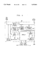
- FIG. 3 is a diagram of a portion of the server of the portion of the ITV system of FIG. 1;
- FIG. 4 is a flowchart showing the operation of the server when a channel is spun-off.
- FIG. 5 is a block diagram of the set top box (e.g., converter) shown in FIG. 2.
- FIG. 1 shows an ITV system. Headend equipment 101, feeders 102, branches 103, a set of subscriber locations 104, broadcast receivers 110, satellite receivers 111, local sources 112, an ITV server 120, a programming center 121, and a program library 122 are all connected as shown. A more detailed description of the interrelationship between the various above-mentioned elements is found in above cited U.S. patent application Ser. No. 07/965493 on page 4, line 1 through page 5, line 14.
- FIG. 2 shows a particular subscriber station 202 in a set of subscriber stations 104.
- the particular subscriber station 202 comprises a set top box 206, a television 208 ("TV"), a videocassette recorder 210 ("VCR"), a stereo system 212, and a computer system 214 connected as shown.
- TV television
- VCR videocassette recorder
- stereo system 212 stereo system 212
- computer system 214 connected as shown.
- Those skilled in the art will appreciate that there are numerous different configurations that are possible due to the different sets of equipment that may be the particular subscriber station. In fact, even within the particular subscriber station 202 shown, there are numerous interconnection possibilities including but not limited to coupling the VCR 210 to the TV 208, the VCR 210 to the stereo system 212, and/or the TV 208 to the stereo system 212.
- FIGS. 3 and 4 An embodiment of the structure and operation of the present invention will now be described with reference to FIGS. 3 and 4, respectively. The description will be made from the point of view of the environment of FIGS. 1 and 2.
- the server 120 is comprised of a processor 302 that may be used to create an extra channel.
- the extra channel is a temporary channel.
- the server 120 obtains its programming material from such sources as the programming center 121 and/or the programming library 122.
- the program library comprises stored data that may include, e.g., versions of movies, musical selections, text, pictorial information, and other material that may be accessed by a subscriber location 104.
- a more detailed description of the server is found in above cited U.S. patent application Ser. No. 07/997985.
- the processor 302 may process, e.g., a version of a movie and transmit it to a viewer over a communications link 124 which connects the server 120 to the headend equipment 101 (see FIG. 1).
- An output port 304 in the server 120 that connects to the communications link 124 serves to transmit a first program (e.g., the version of the movie).
- the processor 302 while showing the first program on a first channel, receives a command to show a second program, e.g., a news brief, on the first channel.
- This command comes from a communications link 126 that links the programming center 121 to the server 120.
- the server 120 defines a temporary channel via block 306.
- the temporary channel is considered “temporary” because the length of time during which the temporary channel is defined is a function of the length of the second program. That is, the extra channel is "temporary" in the sense that the second program is "temporary.”
- the temporary channel may be defined for slightly more than fifteen minutes. This time would be used to provide the fifteen minute news brief and also be used to handle any overhead communications needs (e.g., channel set up time, etc.).
- both the first channel and the temporary channel are virtual channels.
- the second program there is no longer a need for both the temporary channel and the first channel.
- the temporary channel may be eliminated. In this situation, the set of subscriber stations that were tuned to the temporary channel should be informed that the first program is being continued (or will be continued in a predetermined amount of time) on the first channel.
- block 306 is comprised of a channel provider 308, a first program reassignor 310, and a channel informer 312 connected as shown.
- the channel provider 308 receives a signal on line 314 from the processor 302 instructing the channel provider 308 to provide a temporary channel onto which a signal from line 316 (the line inputting the first program to the server) will be placed.
- the channel provider 308 instructs the first program reassignor 310, via line 318, to reassign the first program to the temporary channel.
- the signal on line 314 instructs the channel provider 308 to have the channel informer 312 insert a message in the first channel that will inform viewers that the first program is now being shown on the temporary channel.
- a signal on line 320 represents the second program (with the information from the channel informer 312 inserted therein).
- a signal on line 322 represents the first program that has been reassigned to the temporary channel.
- the signal on line 320 and the signal on line 322 are sent into the output port 304 for transmission to the headend equipment 101.
- the headend equipment 101 eventually makes available the first program and the second program to appropriate subscriber locations 104 via feeders 102 and branches 103.
- the process of "spinning off" a channel is shown.
- the process results in the temporary or extra channel.
- the server 120 in conjunction with other equipment such as the headend equipment 101, begins to transmit the first program. This may be done by sending a first packet of information (e.g., data) as shown in box 404. As shown in boxes 406, 408, and 410, additional packets of information are sent provided that an interrupt is not encountered.
- a first packet of information e.g., data
- box 406 need not be represented by a line of code (or lines of code) but may be implemented in hardware.
- the server must be able to detect and process interrupts, the manner in which interrupts are detected and processed may vary.
- packets of information will be sent in accordance with box 408 until the first program is finished. Thus, only one channel is used.
- the second program will be identified in accordance with box 412.
- the temporary channel will be provided in accordance with box 414.
- the server 120 will continue to send packets of information representing the first program in accordance with box 416. However, these packets will be sent on the temporary channel as opposed to the first channel. Thus, the first program has been "spun-off.”
- box 416 should contain a counter for the packet number similar, if not identical, to the counter shown in box 410.
- the server 120 will begin sending packets of information representing the second program in accordance with box 418. This is done in response to a flag that is set in box 414.
- the first channel will contain information (e.g., a message that appears at the bottom of a TV screen when the packets of information are decoded and displayed) informing viewers that the first program is being shown on the temporary channel.
- information e.g., a message that appears at the bottom of a TV screen when the packets of information are decoded and displayed
- the first program if incomplete, may be switched back to being shown on the first channel.
- box 420 need not be represented by a line of code (or lines of code) but may be implemented in hardware.
- the server must be able to detect completion of the first program, the manner in which completion of the first program is detected may vary.
- FIG. 5 a more detailed view of the set top box 206 of FIG. 2 is shown.
- the structure and operation of FIG. 5 are described in detail in above-cited U.S. patent application Ser. No. 07/965,492 on at least page 5, line 1 through page 7, line 25.
- the controller 514 is described as having both random access memory and read only memory.
- a user defined profile (“the profile") is stored in the RAM of the controller 514 of the set top box 206. In this manner, the user may update/modify the profile depending, e.g., upon what the user will watch during the day/week/month, etc. . . .
- the controller 514 also provides the ability to automatically transfer a selected channel from a first channel to a temporary channel if a first program is spun-off from the first channel to the temporary channel.
- the controller 514 would determine if and when to automatically transfer based upon the profile. Thus, the profile would be accessed to determine if the viewer desires channel spin-off.
- profiles entered by a viewer may be used to ensure that VCRs will record what they were programmed to record. In a basic form, this may be accomplished by a viewer by simply inserting the times and dates of all programs to be recorded into the "profile.” Thus, even if the program being recorded is spun-off, the system accounts for this by automatically changing to the temporary channel. Further, profiles may be entered in accordance with certain channels as opposed to certain time. In this manner, a viewer's channel may be automatically changed if the first channel is a preselected channel. Also, while the profile has been described as being stored in the RAM of the set top box 206, those skilled in the art will realize that the profile could easily be stored in the server 120 or other location.
- the profile of viewers whose TV sets have picture-in-picture (“PIP") capability could specify that the first program be shown in a box that is a small portion of the TV screen and the second program be shown in a large portion of the TV screen, or vice versa (as is commonly done in PIP TV sets today). Additionally, a profile could specify that the first program be recorded while the second program is viewed, or vice versa. This could be accomplished by, e.g., having an infrared transmitter in the set top box 106 that communicates with a VCR to turn the VCR on and start recording either the first channel or the temporary channel. The infrared transmitter would use conventional technology known to those skilled in the art.
- the communications between the set top box 106 and the VCR may be hard wired (e.g., a coaxial cable).
- the profile could combine PIP features with recording features such that a viewer watches the first program and the second program using the PIP feature and also records either the first program or the second program at the same time.
- the first program could continue to be transmitted on the first channel.
- the second program would be shown on the temporary channel.
- Viewers of the first channel could be informed that the temporary channel may be of interest to the viewers with a message such as "Please turn to channel 57 for late breaking news.”
- viewers could be prompted as to their choice of channels. For instance, if the first program is spun-off onto the temporary channel, there could be a prompt that states, e.g., "Press here to continue watching [first program name]." If a viewer does, in fact, direct an uplink signal in such an area, the system would switch to the temporary channel automatically. Otherwise, the viewer would simply continue viewing the first channel.
- first channel and temporary channel may both be virtual channels
- the invention may be utilized in an environment in which only one of the channels is a virtual channel. Still further, if an interrupt is encountered and the second program is complete, the first program could continue to be shown on the temporary channel (as opposed to switching back to the first channel as shown in FIG. 4). Further, the structure and operation of the present invention as described with reference to FIGS. 3 and 4, respectively, need not reside only in the server 120. The structure used to execute the described operations of FIG. 4 may be in the headend equipment 101 or the server 120 and headend equipment 101. Also, although the length of time during which the temporary channel is defined is a function of the length of time of the second program, the temporary channel may be used more than once.
- the second program may be shown in response to a subscriber request.
- a subscriber may be watching a commercial and request additional information about a product and/or service via a "hot button.”
- the systems response to this would be to spin-off a channel, enabling the subscriber to receive additional information and also enabling other subscribers to continue viewing the first program.
Abstract
Description
Claims (31)
Priority Applications (8)
| Application Number | Priority Date | Filing Date | Title |
|---|---|---|---|
| US08/364,628 US5539451A (en) | 1994-12-27 | 1994-12-27 | Method and apparatus for channel spinning off a channel |
| TW084104897A TW306114B (en) | 1994-12-27 | 1995-05-17 | |
| EP95308950A EP0720368B1 (en) | 1994-12-27 | 1995-12-11 | Method and apparatus for channel spinning off a channel |
| DE69521348T DE69521348T2 (en) | 1994-12-27 | 1995-12-11 | Device that can be used in a program transmission system |
| EP99104262A EP0930784B1 (en) | 1994-12-27 | 1995-12-11 | Device for use in program transmission systems |
| DE69515283T DE69515283T2 (en) | 1994-12-27 | 1995-12-11 | Device and method for generating a secondary channel from a primary channel |
| CA002164897A CA2164897C (en) | 1994-12-27 | 1995-12-11 | Method and apparatus for channel spinning off a channel |
| JP7338924A JP3034791B2 (en) | 1994-12-27 | 1995-12-26 | System for transmitting a program, method for using the system and apparatus for transmitting a program |
Applications Claiming Priority (1)
| Application Number | Priority Date | Filing Date | Title |
|---|---|---|---|
| US08/364,628 US5539451A (en) | 1994-12-27 | 1994-12-27 | Method and apparatus for channel spinning off a channel |
Publications (1)
| Publication Number | Publication Date |
|---|---|
| US5539451A true US5539451A (en) | 1996-07-23 |
Family
ID=23435365
Family Applications (1)
| Application Number | Title | Priority Date | Filing Date |
|---|---|---|---|
| US08/364,628 Expired - Lifetime US5539451A (en) | 1994-12-27 | 1994-12-27 | Method and apparatus for channel spinning off a channel |
Country Status (6)
| Country | Link |
|---|---|
| US (1) | US5539451A (en) |
| EP (2) | EP0720368B1 (en) |
| JP (1) | JP3034791B2 (en) |
| CA (1) | CA2164897C (en) |
| DE (2) | DE69521348T2 (en) |
| TW (1) | TW306114B (en) |
Cited By (26)
| Publication number | Priority date | Publication date | Assignee | Title |
|---|---|---|---|---|
| US5835717A (en) * | 1995-12-13 | 1998-11-10 | Silicon Graphics, Inc. | System and method for saving state information in an interactive television system |
| US5892508A (en) * | 1995-04-25 | 1999-04-06 | Bellsouth Corporation | System and method for providing television services |
| WO1999021360A1 (en) * | 1997-10-17 | 1999-04-29 | Polycom, Inc. | Integrated videoconferencing unit |
| US6219041B1 (en) * | 1997-09-30 | 2001-04-17 | Compaq Computer Corporation | Universal user interface for a system utilizing multiple processes |
| US20020009058A1 (en) * | 2000-04-14 | 2002-01-24 | Frank Kelly | System and method for performing auto-commissioning in a two-way satellite system |
| US20020056105A1 (en) * | 2000-02-09 | 2002-05-09 | Ming Wei | Method and system for providing additional information to an advertisement being viewed |
| US20020059604A1 (en) * | 1999-09-16 | 2002-05-16 | Papagan Kenneth M. | System and method for linking media content |
| US6519283B1 (en) | 1999-01-25 | 2003-02-11 | International Business Machines Corporation | Integrated video processing system having multiple video sources and implementing picture-in-picture with on-screen display graphics |
| US20030142129A1 (en) * | 2002-01-31 | 2003-07-31 | Kleven Michael L. | Content processing and distribution systems and processes |
| US20040064835A1 (en) * | 2002-09-26 | 2004-04-01 | International Business Machines Corporation | System and method for content based on-demand video media overlay |
| US20040268385A1 (en) * | 2003-06-30 | 2004-12-30 | Gray James Harold | User originated content notification |
| US20040268401A1 (en) * | 2003-06-30 | 2004-12-30 | Gray James Harold | System and method for providing interactive media content over a network |
| US20040268417A1 (en) * | 2003-06-30 | 2004-12-30 | Gray James Harold | System and method for providing enhanced hot key functionality |
| US20040268416A1 (en) * | 2003-06-30 | 2004-12-30 | Gray James Harold | System and method for providing enhanced hot key control |
| US20050138668A1 (en) * | 2003-12-19 | 2005-06-23 | Bellsouth Intellectual Property Corporation | System and method for enhanced hot key delivery |
| US20070136773A1 (en) * | 2005-12-14 | 2007-06-14 | O'neil Douglas | Systems and methods for providing television services using implicit content to indicate the availability of additional content |
| US20070150338A1 (en) * | 2005-12-22 | 2007-06-28 | Dale Malik | Systems, methods and computer programs for enabling interactive viewer control of advertising content |
| US20070155506A1 (en) * | 2005-12-15 | 2007-07-05 | Dale Malik | System, method and computer program for enabling an interactive game |
| US20070168884A1 (en) * | 2006-01-13 | 2007-07-19 | Phillip Weeks | Systems, methods, and computer program products for providing interactive content |
| US20070186269A1 (en) * | 2006-02-08 | 2007-08-09 | Dale Malik | Interactive program manager and methods for presenting program content |
| US20070208766A1 (en) * | 2006-03-02 | 2007-09-06 | Dale Malik | Apparatuses and methods for interactive communication concerning multimedia content |
| US20070242783A1 (en) * | 2004-09-30 | 2007-10-18 | Matsushita Electric Industrial Co., Ltd. | Digital Broadcast Reception Device |
| US7313810B1 (en) | 1997-09-25 | 2007-12-25 | The Weather Channel | Multimedia information transmission and distribution system |
| US20080127254A1 (en) * | 2006-09-22 | 2008-05-29 | Satoshi Nakajima | Subscriber based tv operation |
| US20140130114A1 (en) * | 2011-09-22 | 2014-05-08 | University Of Seoul Industry Cooperation Foundation | Apparatus and method of playing broadcast content in broadcasting system |
| US11051069B2 (en) * | 2016-03-11 | 2021-06-29 | Samsung Electronics Co., Ltd. | Apparatus and method for providing service in digital broadcasting system |
Families Citing this family (16)
| Publication number | Priority date | Publication date | Assignee | Title |
|---|---|---|---|---|
| DE19754983A1 (en) * | 1997-12-11 | 1999-06-17 | Frank Dr Haertig | Method of transmitting and showing information, especially TV films |
| JPH11187324A (en) * | 1997-12-19 | 1999-07-09 | Matsushita Electric Ind Co Ltd | Program information preparing device, its method and receiver |
| US7168086B1 (en) | 1998-11-30 | 2007-01-23 | Microsoft Corporation | Proxy for video on demand server control |
| US6804825B1 (en) | 1998-11-30 | 2004-10-12 | Microsoft Corporation | Video on demand methods and systems |
| US6628302B2 (en) * | 1998-11-30 | 2003-09-30 | Microsoft Corporation | Interactive video programming methods |
| US6392664B1 (en) | 1998-11-30 | 2002-05-21 | Webtv Networks, Inc. | Method and system for presenting television programming and interactive entertainment |
| JP4515602B2 (en) * | 2000-06-09 | 2010-08-04 | マスプロ電工株式会社 | CATV system headend |
| CA2349914C (en) * | 2000-06-09 | 2013-07-30 | Invidi Technologies Corp. | Advertising delivery method |
| US7730509B2 (en) | 2001-06-08 | 2010-06-01 | Invidi Technologies Corporation | Asset delivery reporting in a broadcast network |
| CN101076990A (en) * | 2004-12-13 | 2007-11-21 | 皇家飞利浦电子股份有限公司 | Delivering streaming data |
| ES2796626T3 (en) | 2005-01-12 | 2020-11-27 | Invidi Tech Corp | Targeted Impression Model for Broadcast Network Resource Delivery |
| US7698236B2 (en) | 2006-05-02 | 2010-04-13 | Invidi Technologies Corporation | Fuzzy logic based viewer identification for targeted asset delivery system |
| WO2007146961A2 (en) | 2006-06-12 | 2007-12-21 | Invidi Technologies Corporation | System and method for inserting media based on keyword search |
| US20100037255A1 (en) | 2008-08-06 | 2010-02-11 | Patrick Sheehan | Third party data matching for targeted advertising |
| WO2009140691A2 (en) | 2008-05-16 | 2009-11-19 | Invidi Technologies Corporation | Request for information related to broadcast network content |
| CA2733193C (en) | 2008-08-05 | 2016-11-01 | Invidi Technologies Corporation | National insertion of targeted advertisment |
Citations (6)
| Publication number | Priority date | Publication date | Assignee | Title |
|---|---|---|---|---|
| US4908859A (en) * | 1986-09-19 | 1990-03-13 | M/A-Com Government Systems, Inc. | Receiver access interface to service components in television channel |
| US5206722A (en) * | 1990-12-28 | 1993-04-27 | At&T Bell Laboratories | Remote channel switching for video on demand service |
| US5226904A (en) * | 1991-02-08 | 1993-07-13 | Conmed Corporation | Electrosurgical instrument |
| US5359601A (en) * | 1992-10-30 | 1994-10-25 | Scientific-Atlanta, Inc. | Apparatus providing dynamic virtual service selection in a multi-service communications system |
| US5418559A (en) * | 1992-10-23 | 1995-05-23 | At&T Corp. | Multi-channel television converter for conventional and interactive signals |
| US5440490A (en) * | 1992-11-20 | 1995-08-08 | Rolls-Royce Plc | Aircraft engine emergency control system |
Family Cites Families (7)
| Publication number | Priority date | Publication date | Assignee | Title |
|---|---|---|---|---|
| NL202427A (en) | 1954-11-29 | |||
| EP0378889A1 (en) * | 1989-01-19 | 1990-07-25 | Dean A. Corren | Computer system user interface |
| DE3901790A1 (en) * | 1989-01-21 | 1990-07-26 | Gfk Gmbh | METHOD FOR THE REMOTE CONTROLLED REPLACEMENT OF A PARTICULAR PROGRAM PART OF A TELEVISION PROGRAM BY A SEPARATELY SENT PROGRAM PART FOR SPECIFIC SELECTED RECEIVER, HOUSEHOLD TERMINAL DEVICE AND THROUGH THE DRIVE DRIVE |
| US5535321A (en) * | 1991-02-14 | 1996-07-09 | International Business Machines Corporation | Method and apparatus for variable complexity user interface in a data processing system |
| CA2066930C (en) | 1991-06-04 | 1996-08-06 | Gary M. Sach | Tactile feedback switch actuator |
| US5446490A (en) * | 1992-10-23 | 1995-08-29 | At&T Corp. | Interactive television with tailored programming |
| US5697393A (en) | 1995-04-21 | 1997-12-16 | Mirlisena, Sr.; John Raymond | Adjustable anti-freeze faucet assembly |
-
1994
- 1994-12-27 US US08/364,628 patent/US5539451A/en not_active Expired - Lifetime
-
1995
- 1995-05-17 TW TW084104897A patent/TW306114B/zh active
- 1995-12-11 DE DE69521348T patent/DE69521348T2/en not_active Revoked
- 1995-12-11 CA CA002164897A patent/CA2164897C/en not_active Expired - Fee Related
- 1995-12-11 EP EP95308950A patent/EP0720368B1/en not_active Expired - Lifetime
- 1995-12-11 EP EP99104262A patent/EP0930784B1/en not_active Revoked
- 1995-12-11 DE DE69515283T patent/DE69515283T2/en not_active Expired - Lifetime
- 1995-12-26 JP JP7338924A patent/JP3034791B2/en not_active Expired - Lifetime
Patent Citations (6)
| Publication number | Priority date | Publication date | Assignee | Title |
|---|---|---|---|---|
| US4908859A (en) * | 1986-09-19 | 1990-03-13 | M/A-Com Government Systems, Inc. | Receiver access interface to service components in television channel |
| US5206722A (en) * | 1990-12-28 | 1993-04-27 | At&T Bell Laboratories | Remote channel switching for video on demand service |
| US5226904A (en) * | 1991-02-08 | 1993-07-13 | Conmed Corporation | Electrosurgical instrument |
| US5418559A (en) * | 1992-10-23 | 1995-05-23 | At&T Corp. | Multi-channel television converter for conventional and interactive signals |
| US5359601A (en) * | 1992-10-30 | 1994-10-25 | Scientific-Atlanta, Inc. | Apparatus providing dynamic virtual service selection in a multi-service communications system |
| US5440490A (en) * | 1992-11-20 | 1995-08-08 | Rolls-Royce Plc | Aircraft engine emergency control system |
Cited By (45)
| Publication number | Priority date | Publication date | Assignee | Title |
|---|---|---|---|---|
| US20030121051A1 (en) * | 1995-04-25 | 2003-06-26 | Howe Wayne R. | System and method for providing television services |
| US5892508A (en) * | 1995-04-25 | 1999-04-06 | Bellsouth Corporation | System and method for providing television services |
| US8490145B2 (en) | 1995-04-25 | 2013-07-16 | At&T Intellectual Property I, L.P. | System and method for providing television services |
| US20070107035A1 (en) * | 1995-04-25 | 2007-05-10 | Howe Wayne R | System and method for providing television services |
| US8819758B2 (en) | 1995-04-25 | 2014-08-26 | At&T Intellectual Property I, L.P. | System and method for providing television services |
| US8914839B2 (en) | 1995-04-25 | 2014-12-16 | At&T Intellectual Property I, L.P. | System and method for providing television services |
| US8966542B2 (en) | 1995-04-25 | 2015-02-24 | At&T Intellectual Property I, L.P. | System and method for providing media content and interactive content |
| US5835717A (en) * | 1995-12-13 | 1998-11-10 | Silicon Graphics, Inc. | System and method for saving state information in an interactive television system |
| US7313810B1 (en) | 1997-09-25 | 2007-12-25 | The Weather Channel | Multimedia information transmission and distribution system |
| US6219041B1 (en) * | 1997-09-30 | 2001-04-17 | Compaq Computer Corporation | Universal user interface for a system utilizing multiple processes |
| US5900907A (en) * | 1997-10-17 | 1999-05-04 | Polycom, Inc. | Integrated videoconferencing unit |
| WO1999021360A1 (en) * | 1997-10-17 | 1999-04-29 | Polycom, Inc. | Integrated videoconferencing unit |
| US6519283B1 (en) | 1999-01-25 | 2003-02-11 | International Business Machines Corporation | Integrated video processing system having multiple video sources and implementing picture-in-picture with on-screen display graphics |
| US20020059604A1 (en) * | 1999-09-16 | 2002-05-16 | Papagan Kenneth M. | System and method for linking media content |
| US20020056105A1 (en) * | 2000-02-09 | 2002-05-09 | Ming Wei | Method and system for providing additional information to an advertisement being viewed |
| US20020009058A1 (en) * | 2000-04-14 | 2002-01-24 | Frank Kelly | System and method for performing auto-commissioning in a two-way satellite system |
| US20030142129A1 (en) * | 2002-01-31 | 2003-07-31 | Kleven Michael L. | Content processing and distribution systems and processes |
| US20040064835A1 (en) * | 2002-09-26 | 2004-04-01 | International Business Machines Corporation | System and method for content based on-demand video media overlay |
| US20040268385A1 (en) * | 2003-06-30 | 2004-12-30 | Gray James Harold | User originated content notification |
| US20040268401A1 (en) * | 2003-06-30 | 2004-12-30 | Gray James Harold | System and method for providing interactive media content over a network |
| US20040268417A1 (en) * | 2003-06-30 | 2004-12-30 | Gray James Harold | System and method for providing enhanced hot key functionality |
| US8635643B2 (en) | 2003-06-30 | 2014-01-21 | At&T Intellectual Property I, L.P. | System and method for providing interactive media content over a network |
| US20040268416A1 (en) * | 2003-06-30 | 2004-12-30 | Gray James Harold | System and method for providing enhanced hot key control |
| US8286203B2 (en) | 2003-12-19 | 2012-10-09 | At&T Intellectual Property I, L.P. | System and method for enhanced hot key delivery |
| US9544646B2 (en) | 2003-12-19 | 2017-01-10 | At&T Intellectual Property I, L.P. | System and method for enhanced hot key delivery |
| US20050138668A1 (en) * | 2003-12-19 | 2005-06-23 | Bellsouth Intellectual Property Corporation | System and method for enhanced hot key delivery |
| US20070242783A1 (en) * | 2004-09-30 | 2007-10-18 | Matsushita Electric Industrial Co., Ltd. | Digital Broadcast Reception Device |
| US8094241B2 (en) * | 2004-09-30 | 2012-01-10 | Panasonic Corporation | Digital broadcast reception device and related method to determine programs included in receivable programs |
| US20070136773A1 (en) * | 2005-12-14 | 2007-06-14 | O'neil Douglas | Systems and methods for providing television services using implicit content to indicate the availability of additional content |
| US8651960B2 (en) | 2005-12-15 | 2014-02-18 | At&T Intellectual Property I, L.P. | System, method and computer program for enabling an interactive game |
| US20070155506A1 (en) * | 2005-12-15 | 2007-07-05 | Dale Malik | System, method and computer program for enabling an interactive game |
| US8317618B2 (en) | 2005-12-15 | 2012-11-27 | At&T Intellectual Property I, Lp | System, method and computer program for enabling an interactive game |
| US20070150338A1 (en) * | 2005-12-22 | 2007-06-28 | Dale Malik | Systems, methods and computer programs for enabling interactive viewer control of advertising content |
| US8161412B2 (en) | 2006-01-13 | 2012-04-17 | At&T Intellectual Property I, L.P. | Systems, methods, and computer program products for providing interactive content |
| US20070168884A1 (en) * | 2006-01-13 | 2007-07-19 | Phillip Weeks | Systems, methods, and computer program products for providing interactive content |
| US20070186269A1 (en) * | 2006-02-08 | 2007-08-09 | Dale Malik | Interactive program manager and methods for presenting program content |
| US9218106B2 (en) | 2006-02-08 | 2015-12-22 | At&T Intellectual Property I, L.P. | Interactive program manager and methods for presenting program content |
| US9544648B2 (en) | 2006-02-08 | 2017-01-10 | At&T Intellectual Property I, L.P. | Interactive program manager and methods for presenting program content |
| US8402503B2 (en) | 2006-02-08 | 2013-03-19 | At& T Intellectual Property I, L.P. | Interactive program manager and methods for presenting program content |
| US10735812B2 (en) | 2006-02-08 | 2020-08-04 | At&T Intellectual Property I, L.P. | Interactive program manager and methods for presenting program content |
| US20070208766A1 (en) * | 2006-03-02 | 2007-09-06 | Dale Malik | Apparatuses and methods for interactive communication concerning multimedia content |
| US8065710B2 (en) | 2006-03-02 | 2011-11-22 | At& T Intellectual Property I, L.P. | Apparatuses and methods for interactive communication concerning multimedia content |
| US20080127254A1 (en) * | 2006-09-22 | 2008-05-29 | Satoshi Nakajima | Subscriber based tv operation |
| US20140130114A1 (en) * | 2011-09-22 | 2014-05-08 | University Of Seoul Industry Cooperation Foundation | Apparatus and method of playing broadcast content in broadcasting system |
| US11051069B2 (en) * | 2016-03-11 | 2021-06-29 | Samsung Electronics Co., Ltd. | Apparatus and method for providing service in digital broadcasting system |
Also Published As
| Publication number | Publication date |
|---|---|
| EP0930784A1 (en) | 1999-07-21 |
| JP3034791B2 (en) | 2000-04-17 |
| JPH08242439A (en) | 1996-09-17 |
| CA2164897C (en) | 1999-12-28 |
| DE69521348D1 (en) | 2001-07-19 |
| DE69515283D1 (en) | 2000-04-06 |
| DE69521348T2 (en) | 2002-04-18 |
| EP0720368A1 (en) | 1996-07-03 |
| EP0930784B1 (en) | 2001-06-13 |
| EP0720368B1 (en) | 2000-03-01 |
| DE69515283T2 (en) | 2000-10-05 |
| CA2164897A1 (en) | 1996-06-28 |
| TW306114B (en) | 1997-05-21 |
Similar Documents
| Publication | Publication Date | Title |
|---|---|---|
| US5539451A (en) | Method and apparatus for channel spinning off a channel | |
| KR101755081B1 (en) | Program guide system with video-on-demand browsing | |
| JP4361135B2 (en) | Improvement of TV signal receiver | |
| CA2438947C (en) | Systems and methods for interactive program guides with personal video recording features | |
| EP0954176B1 (en) | Reminder system for broadcast and non-broadcast events | |
| AU708574B2 (en) | Merging multi-source information in a television system | |
| JP2002521926A (en) | Navigation system for multi-channel digital television system | |
| AU2002250350A1 (en) | Systems and methods for interactive program guides with personal video recording features | |
| JPH06121262A (en) | Video information edit service system | |
| KR100834302B1 (en) | TV signal receiver |
Legal Events
| Date | Code | Title | Description |
|---|---|---|---|
| AS | Assignment |
Owner name: AT&T IPM CORP. Free format text: ASSIGNMENT OF ASSIGNORS INTEREST;ASSIGNORS:CAREY, JOHN THOMAS;TAYLOR, BARBARA ANNE;REEL/FRAME:007402/0478;SIGNING DATES FROM 19950315 TO 19950321 |
|
| STCF | Information on status: patent grant |
Free format text: PATENTED CASE |
|
| FEPP | Fee payment procedure |
Free format text: PAYOR NUMBER ASSIGNED (ORIGINAL EVENT CODE: ASPN); ENTITY STATUS OF PATENT OWNER: LARGE ENTITY |
|
| FPAY | Fee payment |
Year of fee payment: 4 |
|
| AS | Assignment |
Owner name: THE CHASE MANHATTAN BANK, AS COLLATERAL AGENT, TEX Free format text: CONDITIONAL ASSIGNMENT OF AND SECURITY INTEREST IN PATENT RIGHTS;ASSIGNOR:LUCENT TECHNOLOGIES INC. (DE CORPORATION);REEL/FRAME:011722/0048 Effective date: 20010222 |
|
| FEPP | Fee payment procedure |
Free format text: PAYER NUMBER DE-ASSIGNED (ORIGINAL EVENT CODE: RMPN); ENTITY STATUS OF PATENT OWNER: LARGE ENTITY Free format text: PAYOR NUMBER ASSIGNED (ORIGINAL EVENT CODE: ASPN); ENTITY STATUS OF PATENT OWNER: LARGE ENTITY |
|
| FPAY | Fee payment |
Year of fee payment: 8 |
|
| AS | Assignment |
Owner name: LUCENT TECHNOLOGIES INC., NEW JERSEY Free format text: TERMINATION AND RELEASE OF SECURITY INTEREST IN PATENT RIGHTS;ASSIGNOR:JPMORGAN CHASE BANK, N.A. (FORMERLY KNOWN AS THE CHASE MANHATTAN BANK), AS ADMINISTRATIVE AGENT;REEL/FRAME:018584/0446 Effective date: 20061130 |
|
| FEPP | Fee payment procedure |
Free format text: PAYOR NUMBER ASSIGNED (ORIGINAL EVENT CODE: ASPN); ENTITY STATUS OF PATENT OWNER: LARGE ENTITY Free format text: PAYER NUMBER DE-ASSIGNED (ORIGINAL EVENT CODE: RMPN); ENTITY STATUS OF PATENT OWNER: LARGE ENTITY |
|
| FPAY | Fee payment |
Year of fee payment: 12 |
|
| AS | Assignment |
Owner name: CREDIT SUISSE AG, NEW YORK Free format text: SECURITY INTEREST;ASSIGNOR:ALCATEL-LUCENT USA INC.;REEL/FRAME:030510/0627 Effective date: 20130130 |
|
| AS | Assignment |
Owner name: ALCATEL-LUCENT USA INC., NEW JERSEY Free format text: RELEASE BY SECURED PARTY;ASSIGNOR:CREDIT SUISSE AG;REEL/FRAME:033949/0531 Effective date: 20140819 |