US5530786A - Holding for optical fiber splice couplings - Google Patents
Holding for optical fiber splice couplings Download PDFInfo
- Publication number
- US5530786A US5530786A US08/453,739 US45373995A US5530786A US 5530786 A US5530786 A US 5530786A US 45373995 A US45373995 A US 45373995A US 5530786 A US5530786 A US 5530786A
- Authority
- US
- United States
- Prior art keywords
- splice
- fiber
- coupling
- set forth
- channel
- Prior art date
- Legal status (The legal status is an assumption and is not a legal conclusion. Google has not performed a legal analysis and makes no representation as to the accuracy of the status listed.)
- Expired - Lifetime
Links
Images


Classifications
-
- G—PHYSICS
- G02—OPTICS
- G02B—OPTICAL ELEMENTS, SYSTEMS OR APPARATUS
- G02B6/00—Light guides; Structural details of arrangements comprising light guides and other optical elements, e.g. couplings
- G02B6/24—Coupling light guides
- G02B6/36—Mechanical coupling means
- G02B6/38—Mechanical coupling means having fibre to fibre mating means
- G02B6/3801—Permanent connections, i.e. wherein fibres are kept aligned by mechanical means
-
- G—PHYSICS
- G02—OPTICS
- G02B—OPTICAL ELEMENTS, SYSTEMS OR APPARATUS
- G02B6/00—Light guides; Structural details of arrangements comprising light guides and other optical elements, e.g. couplings
- G02B6/44—Mechanical structures for providing tensile strength and external protection for fibres, e.g. optical transmission cables
- G02B6/4439—Auxiliary devices
- G02B6/4471—Terminating devices ; Cable clamps
Definitions
- the present invention relates to the field of optical fiber interconnection and more particularly to holders for fiber-to-fiber splice connections.
- a plurality of pairs of associated optical fibers are to be interconnected and such interconnections must thereafter be held securely and carefully, usually in an organizer tray or cassette within a larger enclosure or cabinet, and usually in an array of such trays or cassettes.
- Such trays must also hold generous portions of the fibers adjacent the interconnections, or splices, to permit splice repair without requiring cable replacement.
- the trays or cassettes also provide for securing jacketed portions of the cables containing one or more of the optical fibers, at ends of the trays.
- the splice connections comprise fusion of the ends or end lengths of the associated optical fibers, or adhesive bonding, or precision clamping, and the thus-fused fiber ends are preferably maintained within a protective sleeve or adapter to maintain the precision alignment of the fibers and provide a level of physical protection and strain relief to the splice coupling.
- the present invention comprises a member of resilient material for holding splice couplings of fiber optic members such as single fibers or of multi-fiber ribbon cable.
- An array of first channels extend from a first end to an opposed second end.
- Each first channel has a general width about equal to the diameter of a single-fiber splice coupling, and a depth equal to twice the diameter of a single-fiber splice coupling;
- each first channel has a first constriction at its entrance along the top surface and a second constriction midway to the channel bottom, thus defining upper and lower positions for each first channel to hold a pair of single-fiber splice couplings within its upper and lower portions.
- second channels are optionally provided that have a large diameter sufficient to contain multi-fiber or mass fusion splice couplings of ribbon cable, with a constriction at the channel entrance along the top surface to hold the mass fusion splice coupling therein.
- Being made of elastomeric material enables the holder to hold each splice coupling in a respective channel under a modest level of compression.
- a splice holder has a splice holding central portion, a flat base section extending from opposed ends of the central portion, and strain relief portions spaced from the central portion having an array of narrow width slots into which are fitted single fibers and ribbon cable extending from splice couplings disposed in the splice holding central portion, relieving the splice couplings from stress by maintaining the fibers and ribbon cable straight as they extend from ends of the splice couplings for a fixed distance.
- An additional advantage of the splice holder member of the present invention is that the member may be extruded.
- FIG. 1 is an isometric view of a splice tray having cable strain relief members at ends thereof and a splice holder of the present invention centrally disposed therebetween;
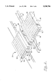
- FIG. 2 is an isometric view of the splice holder of FIG. 1, with representative single-fiber splices and representative ribbon cable splices held therein;
- FIGS. 3 and 4 are plan and elevation views of the splice holder.
- FIG. 5 is an isometric view of an alternate embodiment of the splice holder of the present invention.
- a splice tray or organizer 10 includes a tray body 12 having a bottom wall 14, opposed ends 16,18 and opposed side walls 20,22, as well as a preferably transparent cover member (not shown) that is securable to tray body 12.
- a splice holder 24 of the present invention is affixed to bottom wall 14 centrally positioned between ends 16,18.
- Cable strain relief assemblies 30 are affixed to tray member 12 at respective ends 16,18 such as by fasteners or by use of adhesive or double-sided tape.
- Tray 10 provides substantial fiber-holding space between the ends for generous loops of discrete fibers like fiber 26 and ribbon cable 28 (FIG. 2) to be disposed therein that are preferably covered by the protective lid or cover member placed thereover and affixed to tray body 12.
- Cable strain relief members 30 may be as disclosed in U.S. patent application Ser. No. 08/453,303 filed May 30, 1995 (concurrently herewith)U.S. patent application Ser. No. 08/453,157 filed May 30, 1995 (concurrently herewith) and assigned to the assignee hereof. Strain reliefmember 30 is shown to include a plurality of generally parallel elongate channels 32 formed into and along top surface 34 extending between first and second ends 36,38, with elongate protrusions 40 positioned between adjacent channels 32.
- Channels 32 are dimensioned to receive thereinto, ifdesired, jacketed portions of fibers 26 that have for example diameters of 3 mm, and each is undercut to form retention ledges 42 near top surface 34defining therebetween a constriction less wide than the cable that will hold a jacketed cable 26 in position once inserted.
- Each protrusion 40 preferably has a narrow slot 44 formed thereinto from top surface 34, with narrow slot 44 being dimensioned to approximately equal the thickness of a ribbon cable to receive a ribbon cable 28 thereinto.
- Narrow slot 44 is also of appropriate width to receive thereinto a buffered portion of a single fiber after being broken out fromthe jacket of a cable, if desired.
- the entrance to each slot 44 includes chamfers defining a lead-in facilitating insertion of a ribbon cable thereinto. Slots 44 also can assist in insertion of jacketed cables into channels 32 by allowing upper portions of protrusions 40 to be flexedoutwardly when a cable is urged into the slightly narrower entrance to a channel 32 above retention ledges 42.
- Strain relief holder 30 may also be provided with cable tie apertures 50,52that are formed to be aligned with corresponding apertures (not shown) in the bottom wall 14 of splice tray 10, permitting mounting of conventional cable ties to the splice tray to supplement the strain relief characteristics of the strain relief holder, if desired.
- Cable tie apertures 50 are shown intersecting each channel 32 and are to be used when holder 30 is to be used with ribbon cable that utilizes slots 44, while cable tie apertures 52 are shown intersecting slots 44 that are to be used when holder 30 is to be used with jacketed single fiber cable.
- FIGS. 2 to 4 illustrate a first embodiment of the splice holder 24 of the present invention, a generally thick planar member of elastomeric materialhaving opposed ends 60,62 and opposed side edges 64,66 dimensioned to be placed into splice tray 10 between side walls 20,22 and centrally disposedbetween tray ends (FIG. 1).
- Splice holder 24 may be easily mounted onto bottom wall 14 of splice tray 10 such as by adhesive or cement, or fasteners, or double sided tape and also peelable transfer paper.
- a centrally located aperture 68 is utilized to permit receipt of a vertical rod therethrough for stacking of several splice trays.
- first channels 70 is defined into top surface 72 of holder 24 shown in two regions adjacent side edges 64,66.
- second channels 90 are shown between the two first channel regions and the central region 92 containing aperture 68.
- Each second channel 90 is generally cylindrical, having a depth and diameter equivalent to the outer diameter of a multi-fiber mass fusion splice coupling 94 such as is used with ribbon cable 28.
- Mass fusion splice couplings very similar to coupling 94 may also be used with a plurality of discrete buffered fibers not in ribbon cable form, but that are preferably bonded to each other adjacent and outwardly from the ends of the mass fusion coupling.
- a constriction 98 is defined at the entrance along top surface 72 to hold mass fusion splice coupling 94 therein upon insertion thereinto and therealong.
- Such fusion splice couplings may be formed such as by use of fiber holders applied by a FITEL Optical Fiber Fusion Splicer S198A manufactured by Furukawa Electric and sold by JTS FITEL Inc. of Ottawa, Canada.
- Each first channel 70 has a first constriction 74 defined at the entrance along top surface 72, and each first channel 70 is shown to include a second constriction 76 midway to channel bottom 78 to create upper and lower portions 80,82 each having a general dimension about equal to the diameter of a single-fiber fusion splice coupling 84 used with single fibers 26.
- each first channel 70 can receive and hold two single-fiber splice couplings 84 therein, economizing on space to increasethe density of splice couplings on the splice tray.
- Each splice holder 24 may be made for example of elastomeric material such as SARLINK polypropylene based elastomer, Part No. 3170 or 3160 or 9760 all sold by DSM Thermoplastic Elastomers Inc., Leominster, Mass., and may be extruded rather than individually molded since holder 24 generally has a continuous cross-section therealong, with central aperture 68 being formable by a simple secondary operation.
- SARLINK polypropylene based elastomer Part No. 3170 or 3160 or 9760 all sold by DSM Thermoplastic Elastomers Inc., Leominster, Mass.
- FIG. 5 illustrates a second embodiment of the present invention of splice holder 100.
- a central splice holding portion 102 is shown to have a top surface 104 having formed thereinto generally first channels 106 for single-fiber splice couplings, and second channels 108 for mass fusion splice couplings and may be identical to first and second channels 70,90 of splice holder 24 as shown in FIGS. 1 to 4.
- a thin, flat base portion 110 extends from opposed first and second splice holding ends 112,114 to strain relief regions 116 spaced from first and second ends 112,114.
- Each strain relief region 116 includes an array of narrow width slots 118,120 extending into top surface 104 and aligned with first channels 106 and second channels 108 respectively.
- each slot 118 is equivalentto the diameter of a single buffered fiber, and the width of each slot 120 is equivalent to the thickness of ribbon cable 28.
- Strain relief region 116 thus at least holds a portion of each fiber and ribbon cable at a selected distance from the splice holding central portion 102 and thus serves to isolate the splice couplings from stress resulting from different lateral directions assumed by the portions of the fibers and cables extending from the splice holder.
- the splice holder of the present invention may be utilized independently ofa splice tray if desired by simply being secured to a selected surface in adesired orientation to receive and hold fiber optic couplings such as of discrete or single fiber optic cable or of ribbon cable. Variations and modifications may occur to others that are within the spirit of the invention and the scope of the claims.
Landscapes
- Physics & Mathematics (AREA)
- General Physics & Mathematics (AREA)
- Optics & Photonics (AREA)
- Mechanical Coupling Of Light Guides (AREA)
Abstract
Description
Claims (12)
Priority Applications (5)
| Application Number | Priority Date | Filing Date | Title |
|---|---|---|---|
| US08/453,739 US5530786A (en) | 1995-05-30 | 1995-05-30 | Holding for optical fiber splice couplings |
| EP96916485A EP0871911A1 (en) | 1995-05-30 | 1996-05-15 | Optical fiber splice holder and strain relief |
| CN96194245A CN1185839A (en) | 1995-05-30 | 1996-05-15 | Optical fiber splice holder and strain relief |
| PCT/US1996/007081 WO1996038752A1 (en) | 1995-05-30 | 1996-05-15 | Optical fiber splice holder and strain relief |
| JP8536518A JPH11506219A (en) | 1995-05-30 | 1996-05-15 | Optical fiber splice holder and strain relief |
Applications Claiming Priority (1)
| Application Number | Priority Date | Filing Date | Title |
|---|---|---|---|
| US08/453,739 US5530786A (en) | 1995-05-30 | 1995-05-30 | Holding for optical fiber splice couplings |
Publications (1)
| Publication Number | Publication Date |
|---|---|
| US5530786A true US5530786A (en) | 1996-06-25 |
Family
ID=23801868
Family Applications (1)
| Application Number | Title | Priority Date | Filing Date |
|---|---|---|---|
| US08/453,739 Expired - Lifetime US5530786A (en) | 1995-05-30 | 1995-05-30 | Holding for optical fiber splice couplings |
Country Status (1)
| Country | Link |
|---|---|
| US (1) | US5530786A (en) |
Cited By (58)
| Publication number | Priority date | Publication date | Assignee | Title |
|---|---|---|---|---|
| US5805758A (en) * | 1996-01-25 | 1998-09-08 | Samsung Electronics Co., Ltd. | Optical fiber connector protecting supporter |
| US6195496B1 (en) * | 1999-07-30 | 2001-02-27 | Lucent Technologies, Inc. | Splice holder with tilted mounting feature |
| US6226439B1 (en) * | 1999-07-30 | 2001-05-01 | Lucent Technologies, Inc. | Splice holder with self locking feature |
| US6249636B1 (en) * | 1999-09-07 | 2001-06-19 | Lucent Technologies, Inc. | High density fusion splice holder |
| US6259851B1 (en) * | 1999-09-17 | 2001-07-10 | Lucent Technologies Inc. | High density fiber splice holder |
| US6285815B1 (en) * | 1999-09-07 | 2001-09-04 | Lucent Technologies Inc. | High density fusion splice holder |
| US6298191B1 (en) * | 1999-07-30 | 2001-10-02 | Lucent Technologies, Inc. | Splice mount having improved structural integrity and method of making |
| AU751741B2 (en) * | 1998-08-31 | 2002-08-29 | Whitaker Corporation, The | Fibre optic splice holder |
| FR2821934A1 (en) * | 2001-03-12 | 2002-09-13 | Teem Photonics | PASSAGE GUIDE FOR OPTICAL FIBERS AND RECEPTION BOX FOR OPTICAL COMPONENTS PROVIDED WITH SUCH A GUIDE |
| FR2822250A1 (en) * | 2001-03-14 | 2002-09-20 | Sagem | High capacity optical cable separation/connection mechanism having fixing slab with holes and fibre protection tubes threaded through/screws mechanism position holding two protection tubes |
| US6496638B1 (en) * | 1998-10-23 | 2002-12-17 | Lucent Technologies Inc. | Optical fiber cassette |
| US6494625B1 (en) | 2001-03-19 | 2002-12-17 | At&T Corp. | Color-coded restoration splice block |
| US6512179B1 (en) * | 2001-09-28 | 2003-01-28 | International Business Machines Corporation | Transmission cable strain relief device |
| US6567601B2 (en) * | 2001-06-19 | 2003-05-20 | Lucent Technologies Inc. | Fiber-optic cable routing and management system and components |
| US6701056B2 (en) * | 2002-01-02 | 2004-03-02 | Wavesplitter Technologies, Inc. | Modular, variably configurable retainer assembly for optical components |
| WO2004055568A1 (en) * | 2002-12-12 | 2004-07-01 | Corning Incorporated | Devices for holding optical fiber array and for connecting optical devices with different fibre array pitch |
| US6801704B1 (en) * | 2003-05-30 | 2004-10-05 | Lucent Technologies Inc. | Fiber optics splice holder |
| US20080025685A1 (en) * | 2006-07-25 | 2008-01-31 | Airbus Deutschland Gmbh | Holder for optical fibres |
| WO2008118927A1 (en) * | 2007-03-27 | 2008-10-02 | 3M Innovative Properties Company | Splice apparatus for optical fiber |
| WO2009106874A1 (en) * | 2008-02-29 | 2009-09-03 | Tyco Electronics Raychem Nv | Optical fibre organiser |
| US20100132979A1 (en) * | 2008-11-28 | 2010-06-03 | Deng-Hsi Chen | Wire keeper |
| US20110091179A1 (en) * | 2009-10-19 | 2011-04-21 | Adc Gmbh | Splice holder |
| WO2011094130A1 (en) * | 2010-01-29 | 2011-08-04 | Afl Telecommunications Llc | High fiber count package foam insert |
| US20110280535A1 (en) * | 2010-05-11 | 2011-11-17 | Wade Womack | Splice holder |
| CN102375192A (en) * | 2011-10-19 | 2012-03-14 | 四川九洲线缆有限责任公司 | Special connector for wind power optical cable assembly |
| US20120328258A1 (en) * | 2010-03-10 | 2012-12-27 | David Lopez Barron | Fiber optic cassette |
| US20130108225A1 (en) * | 2011-10-26 | 2013-05-02 | All Systems Broadband, Inc. | Holders for Optical Fiber Splice Sleeves and Passive Optical Components |
| US8712206B2 (en) | 2009-06-19 | 2014-04-29 | Corning Cable Systems Llc | High-density fiber optic modules and module housings and related equipment |
| US8879881B2 (en) | 2010-04-30 | 2014-11-04 | Corning Cable Systems Llc | Rotatable routing guide and assembly |
| US8913866B2 (en) | 2010-03-26 | 2014-12-16 | Corning Cable Systems Llc | Movable adapter panel |
| US8953924B2 (en) | 2011-09-02 | 2015-02-10 | Corning Cable Systems Llc | Removable strain relief brackets for securing fiber optic cables and/or optical fibers to fiber optic equipment, and related assemblies and methods |
| US8985862B2 (en) | 2013-02-28 | 2015-03-24 | Corning Cable Systems Llc | High-density multi-fiber adapter housings |
| US8989547B2 (en) | 2011-06-30 | 2015-03-24 | Corning Cable Systems Llc | Fiber optic equipment assemblies employing non-U-width-sized housings and related methods |
| US8992099B2 (en) | 2010-02-04 | 2015-03-31 | Corning Cable Systems Llc | Optical interface cards, assemblies, and related methods, suited for installation and use in antenna system equipment |
| US8995812B2 (en) | 2012-10-26 | 2015-03-31 | Ccs Technology, Inc. | Fiber optic management unit and fiber optic distribution device |
| US9008485B2 (en) | 2011-05-09 | 2015-04-14 | Corning Cable Systems Llc | Attachment mechanisms employed to attach a rear housing section to a fiber optic housing, and related assemblies and methods |
| US9020320B2 (en) | 2008-08-29 | 2015-04-28 | Corning Cable Systems Llc | High density and bandwidth fiber optic apparatuses and related equipment and methods |
| US9022814B2 (en) | 2010-04-16 | 2015-05-05 | Ccs Technology, Inc. | Sealing and strain relief device for data cables |
| US9042702B2 (en) | 2012-09-18 | 2015-05-26 | Corning Cable Systems Llc | Platforms and systems for fiber optic cable attachment |
| US9038832B2 (en) | 2011-11-30 | 2015-05-26 | Corning Cable Systems Llc | Adapter panel support assembly |
| US9059578B2 (en) | 2009-02-24 | 2015-06-16 | Ccs Technology, Inc. | Holding device for a cable or an assembly for use with a cable |
| US9075217B2 (en) | 2010-04-30 | 2015-07-07 | Corning Cable Systems Llc | Apparatuses and related components and methods for expanding capacity of fiber optic housings |
| US9075216B2 (en) | 2009-05-21 | 2015-07-07 | Corning Cable Systems Llc | Fiber optic housings configured to accommodate fiber optic modules/cassettes and fiber optic panels, and related components and methods |
| US9116324B2 (en) | 2010-10-29 | 2015-08-25 | Corning Cable Systems Llc | Stacked fiber optic modules and fiber optic equipment configured to support stacked fiber optic modules |
| US9213161B2 (en) | 2010-11-05 | 2015-12-15 | Corning Cable Systems Llc | Fiber body holder and strain relief device |
| US9250409B2 (en) | 2012-07-02 | 2016-02-02 | Corning Cable Systems Llc | Fiber-optic-module trays and drawers for fiber-optic equipment |
| US9279951B2 (en) | 2010-10-27 | 2016-03-08 | Corning Cable Systems Llc | Fiber optic module for limited space applications having a partially sealed module sub-assembly |
| US9519118B2 (en) | 2010-04-30 | 2016-12-13 | Corning Optical Communications LLC | Removable fiber management sections for fiber optic housings, and related components and methods |
| US9645317B2 (en) | 2011-02-02 | 2017-05-09 | Corning Optical Communications LLC | Optical backplane extension modules, and related assemblies suitable for establishing optical connections to information processing modules disposed in equipment racks |
| US9791653B2 (en) | 2012-04-03 | 2017-10-17 | CommScope Connectivity Belgium BVBA | Telecommunications enclosure organizer |
| US10094996B2 (en) | 2008-08-29 | 2018-10-09 | Corning Optical Communications, Llc | Independently translatable modules and fiber optic equipment trays in fiber optic equipment |
| US20180319619A1 (en) * | 2017-05-05 | 2018-11-08 | Harvey L. Frierson | Chord Organizer |
| US20190363527A1 (en) * | 2018-05-24 | 2019-11-28 | Beijing Apollo Ding rong Solar Technology Co., Ltd | Cable collecting device, cable guiding device and building component |
| US20200057226A1 (en) * | 2019-02-28 | 2020-02-20 | Commscope Technologies Llc | Optical fiber cassette with monitoring function |
| US10761270B2 (en) * | 2016-06-24 | 2020-09-01 | Commscope, Inc. Of North Carolina | Elastomeric optical fiber alignment and coupling device |
| US10845561B1 (en) * | 2019-06-28 | 2020-11-24 | Afl Telecommunications Llc | Fiber optic cassettes and splice modules |
| US11294135B2 (en) | 2008-08-29 | 2022-04-05 | Corning Optical Communications LLC | High density and bandwidth fiber optic apparatuses and related equipment and methods |
| US20230014214A1 (en) * | 2018-05-14 | 2023-01-19 | Afl Telecommunications Llc | Butt closures and organizer assemblies therefor |
Citations (19)
| Publication number | Priority date | Publication date | Assignee | Title |
|---|---|---|---|---|
| US3768146A (en) * | 1972-02-22 | 1973-10-30 | Bell Telephone Labor Inc | Method of splicing optical fibers |
| US4627686A (en) * | 1984-08-10 | 1986-12-09 | Siecor Corporation | Splicing tray for optical fibers |
| US4687289A (en) * | 1985-09-17 | 1987-08-18 | Brintec Corporation | Fiberoptic splice organizer |
| US4702551A (en) * | 1984-10-11 | 1987-10-27 | Reliance Comm/Tec Corporation | Method and apparatus for handling and storing cabled spliced ends of fiber optics |
| US4793681A (en) * | 1988-04-18 | 1988-12-27 | Gte Products Corporation | Splice cradle |
| US4840449A (en) * | 1988-01-27 | 1989-06-20 | American Telephone And Telegraph Company, At&T Bell Laboratories | Optical fiber splice organizer |
| US4842362A (en) * | 1982-09-14 | 1989-06-27 | Gte Products Corporation | Housing for a fiber optic splice |
| US4854661A (en) * | 1987-11-05 | 1989-08-08 | Gte Products Corporation | Splice cradle |
| US4911521A (en) * | 1988-03-15 | 1990-03-27 | Sumitomo Electric Industries, Ltd. | Connecting box for multi-optical fiber cable |
| US5046811A (en) * | 1989-07-17 | 1991-09-10 | Jung Roger E | Junction box for optical communications cords, and gland assembly for cord |
| US5069523A (en) * | 1988-12-08 | 1991-12-03 | Siemens Aktiengesellschaft | Cassette for spare lengths of light waveguides to be used at the site to be spliced |
| US5071211A (en) * | 1988-12-20 | 1991-12-10 | Northern Telecom Limited | Connector holders and distribution frame and connector holder assemblies for optical cable |
| US5222184A (en) * | 1989-10-10 | 1993-06-22 | Bowthorpe-Hellermann Limited | Optical fibre splice storage tray |
| US5278933A (en) * | 1992-06-30 | 1994-01-11 | Hunsinger Terrance D | Fiber optic splice organizer and associated method |
| US5323480A (en) * | 1992-11-25 | 1994-06-21 | Raychem Corporation | Fiber optic splice closure |
| US5375185A (en) * | 1993-04-30 | 1994-12-20 | Keptel, Inc. | Apparatus for storing and organizing spliced optical fibers |
| US5416882A (en) * | 1992-11-25 | 1995-05-16 | Mars Actel | Device for positioning and retaining optical fibers in a layer |
| US5420956A (en) * | 1993-01-28 | 1995-05-30 | Krone Aktiengesellschaft | Case for passive optical components |
| US5422974A (en) * | 1994-09-23 | 1995-06-06 | The United States Of America As Represented By The Secretary Of The Navy | Shock resistant optic fiber rotary splice holding device |
-
1995
- 1995-05-30 US US08/453,739 patent/US5530786A/en not_active Expired - Lifetime
Patent Citations (19)
| Publication number | Priority date | Publication date | Assignee | Title |
|---|---|---|---|---|
| US3768146A (en) * | 1972-02-22 | 1973-10-30 | Bell Telephone Labor Inc | Method of splicing optical fibers |
| US4842362A (en) * | 1982-09-14 | 1989-06-27 | Gte Products Corporation | Housing for a fiber optic splice |
| US4627686A (en) * | 1984-08-10 | 1986-12-09 | Siecor Corporation | Splicing tray for optical fibers |
| US4702551A (en) * | 1984-10-11 | 1987-10-27 | Reliance Comm/Tec Corporation | Method and apparatus for handling and storing cabled spliced ends of fiber optics |
| US4687289A (en) * | 1985-09-17 | 1987-08-18 | Brintec Corporation | Fiberoptic splice organizer |
| US4854661A (en) * | 1987-11-05 | 1989-08-08 | Gte Products Corporation | Splice cradle |
| US4840449A (en) * | 1988-01-27 | 1989-06-20 | American Telephone And Telegraph Company, At&T Bell Laboratories | Optical fiber splice organizer |
| US4911521A (en) * | 1988-03-15 | 1990-03-27 | Sumitomo Electric Industries, Ltd. | Connecting box for multi-optical fiber cable |
| US4793681A (en) * | 1988-04-18 | 1988-12-27 | Gte Products Corporation | Splice cradle |
| US5069523A (en) * | 1988-12-08 | 1991-12-03 | Siemens Aktiengesellschaft | Cassette for spare lengths of light waveguides to be used at the site to be spliced |
| US5071211A (en) * | 1988-12-20 | 1991-12-10 | Northern Telecom Limited | Connector holders and distribution frame and connector holder assemblies for optical cable |
| US5046811A (en) * | 1989-07-17 | 1991-09-10 | Jung Roger E | Junction box for optical communications cords, and gland assembly for cord |
| US5222184A (en) * | 1989-10-10 | 1993-06-22 | Bowthorpe-Hellermann Limited | Optical fibre splice storage tray |
| US5278933A (en) * | 1992-06-30 | 1994-01-11 | Hunsinger Terrance D | Fiber optic splice organizer and associated method |
| US5323480A (en) * | 1992-11-25 | 1994-06-21 | Raychem Corporation | Fiber optic splice closure |
| US5416882A (en) * | 1992-11-25 | 1995-05-16 | Mars Actel | Device for positioning and retaining optical fibers in a layer |
| US5420956A (en) * | 1993-01-28 | 1995-05-30 | Krone Aktiengesellschaft | Case for passive optical components |
| US5375185A (en) * | 1993-04-30 | 1994-12-20 | Keptel, Inc. | Apparatus for storing and organizing spliced optical fibers |
| US5422974A (en) * | 1994-09-23 | 1995-06-06 | The United States Of America As Represented By The Secretary Of The Navy | Shock resistant optic fiber rotary splice holding device |
Non-Patent Citations (12)
| Title |
|---|
| AMP Catalog 82188, "AMP Fiber Optic Products", p. 147; Feb. 1993; AMP Incorporated, Harrisburg, PA. |
| AMP Catalog 82188, AMP Fiber Optic Products , p. 147; Feb. 1993; AMP Incorporated, Harrisburg, PA. * |
| AMP Instruction Sheet 408 9490, AMP Organizer Holder Kits and Trays , five pages; Mar. 1993; AMP Incorporated, Harrisburg, PA. * |
| AMP Instruction Sheet 408-9490, "AMP Organizer Holder Kits and Trays", five pages; Mar. 1993; AMP Incorporated, Harrisburg, PA. |
| BEJED Drawing, "BJ-1742C-005 12 Fiber Universal Splice Unit"; Feb., 1994; BEJED Communication Products, Portland, OR. |
| BEJED Drawing, BJ 1742C 005 12 Fiber Universal Splice Unit ; Feb., 1994; BEJED Communication Products, Portland, OR. * |
| DSM Brochure, "SARLINK 3000 Thermoplastic Elastometers", three pages, Nov., 1994; DSM Thermoplastic Elastomers, Inc., Leominster, MA. |
| DSM Brochure, SARLINK 3000 Thermoplastic Elastometers , three pages, Nov., 1994; DSM Thermoplastic Elastomers, Inc., Leominster, MA. * |
| Fitel Brochure, "Optical Fiber Fusion Splicer S198A", four pages; JDS Fitel Inc., Ottawa, Canada (No Date). |
| Fitel Brochure, Optical Fiber Fusion Splicer S198A , four pages; JDS Fitel Inc., Ottawa, Canada (No Date). * |
| Siecor Catalog, "Splice Trays", pp. 2-65 to 2-68; Siecor Corporation, Hickory, North Carolina (No Date). |
| Siecor Catalog, Splice Trays , pp. 2 65 to 2 68; Siecor Corporation, Hickory, North Carolina (No Date). * |
Cited By (94)
| Publication number | Priority date | Publication date | Assignee | Title |
|---|---|---|---|---|
| US5805758A (en) * | 1996-01-25 | 1998-09-08 | Samsung Electronics Co., Ltd. | Optical fiber connector protecting supporter |
| AU751741B2 (en) * | 1998-08-31 | 2002-08-29 | Whitaker Corporation, The | Fibre optic splice holder |
| US6496638B1 (en) * | 1998-10-23 | 2002-12-17 | Lucent Technologies Inc. | Optical fiber cassette |
| US6298191B1 (en) * | 1999-07-30 | 2001-10-02 | Lucent Technologies, Inc. | Splice mount having improved structural integrity and method of making |
| US6195496B1 (en) * | 1999-07-30 | 2001-02-27 | Lucent Technologies, Inc. | Splice holder with tilted mounting feature |
| US6226439B1 (en) * | 1999-07-30 | 2001-05-01 | Lucent Technologies, Inc. | Splice holder with self locking feature |
| US6285815B1 (en) * | 1999-09-07 | 2001-09-04 | Lucent Technologies Inc. | High density fusion splice holder |
| US6249636B1 (en) * | 1999-09-07 | 2001-06-19 | Lucent Technologies, Inc. | High density fusion splice holder |
| US6259851B1 (en) * | 1999-09-17 | 2001-07-10 | Lucent Technologies Inc. | High density fiber splice holder |
| US20040071431A1 (en) * | 2001-03-12 | 2004-04-15 | Denis Trouchet | Guide for passing optical fibers and receiving housing for optical components fitted with one such guide |
| FR2821934A1 (en) * | 2001-03-12 | 2002-09-13 | Teem Photonics | PASSAGE GUIDE FOR OPTICAL FIBERS AND RECEPTION BOX FOR OPTICAL COMPONENTS PROVIDED WITH SUCH A GUIDE |
| WO2002073280A2 (en) * | 2001-03-12 | 2002-09-19 | Teem Photonics | Guide for passing optical fibers and receiving housing for optical components fitted with one such guide |
| WO2002073280A3 (en) * | 2001-03-12 | 2002-11-21 | Teem Photonics | Guide for passing optical fibers and receiving housing for optical components fitted with one such guide |
| FR2822250A1 (en) * | 2001-03-14 | 2002-09-20 | Sagem | High capacity optical cable separation/connection mechanism having fixing slab with holes and fibre protection tubes threaded through/screws mechanism position holding two protection tubes |
| US6494625B1 (en) | 2001-03-19 | 2002-12-17 | At&T Corp. | Color-coded restoration splice block |
| US6567601B2 (en) * | 2001-06-19 | 2003-05-20 | Lucent Technologies Inc. | Fiber-optic cable routing and management system and components |
| US6512179B1 (en) * | 2001-09-28 | 2003-01-28 | International Business Machines Corporation | Transmission cable strain relief device |
| US6701056B2 (en) * | 2002-01-02 | 2004-03-02 | Wavesplitter Technologies, Inc. | Modular, variably configurable retainer assembly for optical components |
| WO2004055568A1 (en) * | 2002-12-12 | 2004-07-01 | Corning Incorporated | Devices for holding optical fiber array and for connecting optical devices with different fibre array pitch |
| US6801704B1 (en) * | 2003-05-30 | 2004-10-05 | Lucent Technologies Inc. | Fiber optics splice holder |
| US20080025685A1 (en) * | 2006-07-25 | 2008-01-31 | Airbus Deutschland Gmbh | Holder for optical fibres |
| US7394963B2 (en) * | 2006-07-25 | 2008-07-01 | Airbus Deutschland Gmbh | Holder for optical fibres |
| WO2008118927A1 (en) * | 2007-03-27 | 2008-10-02 | 3M Innovative Properties Company | Splice apparatus for optical fiber |
| CN101276024B (en) * | 2007-03-27 | 2012-09-26 | 3M创新有限公司 | Optical fiber connection protecting box |
| WO2009106874A1 (en) * | 2008-02-29 | 2009-09-03 | Tyco Electronics Raychem Nv | Optical fibre organiser |
| US11609396B2 (en) | 2008-08-29 | 2023-03-21 | Corning Optical Communications LLC | High density and bandwidth fiber optic apparatuses and related equipment and methods |
| US10459184B2 (en) | 2008-08-29 | 2019-10-29 | Corning Optical Communications LLC | High density and bandwidth fiber optic apparatuses and related equipment and methods |
| US10126514B2 (en) | 2008-08-29 | 2018-11-13 | Corning Optical Communications, Llc | Independently translatable modules and fiber optic equipment trays in fiber optic equipment |
| US10416405B2 (en) | 2008-08-29 | 2019-09-17 | Corning Optical Communications LLC | Independently translatable modules and fiber optic equipment trays in fiber optic equipment |
| US11754796B2 (en) | 2008-08-29 | 2023-09-12 | Corning Optical Communications LLC | Independently translatable modules and fiber optic equipment trays in fiber optic equipment |
| US10120153B2 (en) | 2008-08-29 | 2018-11-06 | Corning Optical Communications, Llc | Independently translatable modules and fiber optic equipment trays in fiber optic equipment |
| US10564378B2 (en) | 2008-08-29 | 2020-02-18 | Corning Optical Communications LLC | High density and bandwidth fiber optic apparatuses and related equipment and methods |
| US10094996B2 (en) | 2008-08-29 | 2018-10-09 | Corning Optical Communications, Llc | Independently translatable modules and fiber optic equipment trays in fiber optic equipment |
| US10222570B2 (en) | 2008-08-29 | 2019-03-05 | Corning Optical Communications LLC | Independently translatable modules and fiber optic equipment trays in fiber optic equipment |
| US10606014B2 (en) | 2008-08-29 | 2020-03-31 | Corning Optical Communications LLC | Independently translatable modules and fiber optic equipment trays in fiber optic equipment |
| US9910236B2 (en) | 2008-08-29 | 2018-03-06 | Corning Optical Communications LLC | High density and bandwidth fiber optic apparatuses and related equipment and methods |
| US10422971B2 (en) | 2008-08-29 | 2019-09-24 | Corning Optical Communicatinos LLC | High density and bandwidth fiber optic apparatuses and related equipment and methods |
| US10444456B2 (en) | 2008-08-29 | 2019-10-15 | Corning Optical Communications LLC | High density and bandwidth fiber optic apparatuses and related equipment and methods |
| US11294136B2 (en) | 2008-08-29 | 2022-04-05 | Corning Optical Communications LLC | High density and bandwidth fiber optic apparatuses and related equipment and methods |
| US11294135B2 (en) | 2008-08-29 | 2022-04-05 | Corning Optical Communications LLC | High density and bandwidth fiber optic apparatuses and related equipment and methods |
| US11092767B2 (en) | 2008-08-29 | 2021-08-17 | Corning Optical Communications LLC | High density and bandwidth fiber optic apparatuses and related equipment and methods |
| US9020320B2 (en) | 2008-08-29 | 2015-04-28 | Corning Cable Systems Llc | High density and bandwidth fiber optic apparatuses and related equipment and methods |
| US11086089B2 (en) | 2008-08-29 | 2021-08-10 | Corning Optical Communications LLC | High density and bandwidth fiber optic apparatuses and related equipment and methods |
| US10852499B2 (en) | 2008-08-29 | 2020-12-01 | Corning Optical Communications LLC | High density and bandwidth fiber optic apparatuses and related equipment and methods |
| US20100132979A1 (en) * | 2008-11-28 | 2010-06-03 | Deng-Hsi Chen | Wire keeper |
| US9059578B2 (en) | 2009-02-24 | 2015-06-16 | Ccs Technology, Inc. | Holding device for a cable or an assembly for use with a cable |
| US9075216B2 (en) | 2009-05-21 | 2015-07-07 | Corning Cable Systems Llc | Fiber optic housings configured to accommodate fiber optic modules/cassettes and fiber optic panels, and related components and methods |
| US8712206B2 (en) | 2009-06-19 | 2014-04-29 | Corning Cable Systems Llc | High-density fiber optic modules and module housings and related equipment |
| US20110091179A1 (en) * | 2009-10-19 | 2011-04-21 | Adc Gmbh | Splice holder |
| US8821030B2 (en) | 2010-01-29 | 2014-09-02 | Afl Telecommunications Llc | High fiber count package foam insert |
| US20110217006A1 (en) * | 2010-01-29 | 2011-09-08 | Afl Telecommunications Llc | High fiber count package foam insert |
| WO2011094130A1 (en) * | 2010-01-29 | 2011-08-04 | Afl Telecommunications Llc | High fiber count package foam insert |
| US8992099B2 (en) | 2010-02-04 | 2015-03-31 | Corning Cable Systems Llc | Optical interface cards, assemblies, and related methods, suited for installation and use in antenna system equipment |
| US20120328258A1 (en) * | 2010-03-10 | 2012-12-27 | David Lopez Barron | Fiber optic cassette |
| US8913866B2 (en) | 2010-03-26 | 2014-12-16 | Corning Cable Systems Llc | Movable adapter panel |
| US9022814B2 (en) | 2010-04-16 | 2015-05-05 | Ccs Technology, Inc. | Sealing and strain relief device for data cables |
| US9519118B2 (en) | 2010-04-30 | 2016-12-13 | Corning Optical Communications LLC | Removable fiber management sections for fiber optic housings, and related components and methods |
| US9075217B2 (en) | 2010-04-30 | 2015-07-07 | Corning Cable Systems Llc | Apparatuses and related components and methods for expanding capacity of fiber optic housings |
| US8879881B2 (en) | 2010-04-30 | 2014-11-04 | Corning Cable Systems Llc | Rotatable routing guide and assembly |
| US8254742B2 (en) * | 2010-05-11 | 2012-08-28 | Commscope, Inc. Of North Carolina | Splice holder |
| US20110280535A1 (en) * | 2010-05-11 | 2011-11-17 | Wade Womack | Splice holder |
| US9279951B2 (en) | 2010-10-27 | 2016-03-08 | Corning Cable Systems Llc | Fiber optic module for limited space applications having a partially sealed module sub-assembly |
| US9116324B2 (en) | 2010-10-29 | 2015-08-25 | Corning Cable Systems Llc | Stacked fiber optic modules and fiber optic equipment configured to support stacked fiber optic modules |
| US9213161B2 (en) | 2010-11-05 | 2015-12-15 | Corning Cable Systems Llc | Fiber body holder and strain relief device |
| US10481335B2 (en) | 2011-02-02 | 2019-11-19 | Corning Optical Communications, Llc | Dense shuttered fiber optic connectors and assemblies suitable for establishing optical connections for optical backplanes in equipment racks |
| US9645317B2 (en) | 2011-02-02 | 2017-05-09 | Corning Optical Communications LLC | Optical backplane extension modules, and related assemblies suitable for establishing optical connections to information processing modules disposed in equipment racks |
| US9008485B2 (en) | 2011-05-09 | 2015-04-14 | Corning Cable Systems Llc | Attachment mechanisms employed to attach a rear housing section to a fiber optic housing, and related assemblies and methods |
| US8989547B2 (en) | 2011-06-30 | 2015-03-24 | Corning Cable Systems Llc | Fiber optic equipment assemblies employing non-U-width-sized housings and related methods |
| US8953924B2 (en) | 2011-09-02 | 2015-02-10 | Corning Cable Systems Llc | Removable strain relief brackets for securing fiber optic cables and/or optical fibers to fiber optic equipment, and related assemblies and methods |
| CN102375192A (en) * | 2011-10-19 | 2012-03-14 | 四川九洲线缆有限责任公司 | Special connector for wind power optical cable assembly |
| US20130108225A1 (en) * | 2011-10-26 | 2013-05-02 | All Systems Broadband, Inc. | Holders for Optical Fiber Splice Sleeves and Passive Optical Components |
| US9207422B2 (en) * | 2011-10-26 | 2015-12-08 | All Systems Broadband, Inc. | Holders for optical fiber splice sleeves and passive optical components |
| US9038832B2 (en) | 2011-11-30 | 2015-05-26 | Corning Cable Systems Llc | Adapter panel support assembly |
| US11016257B2 (en) | 2012-04-03 | 2021-05-25 | CommScope Connectivity Belgium BVBA | Telecommunications enclosure and organizer |
| US9791653B2 (en) | 2012-04-03 | 2017-10-17 | CommScope Connectivity Belgium BVBA | Telecommunications enclosure organizer |
| US11747583B2 (en) | 2012-04-03 | 2023-09-05 | CommScope Connectivity Belgium BVBA | Telecommunications enclosure and organizer |
| US10444455B2 (en) | 2012-04-03 | 2019-10-15 | CommScope Connectivity Belgium BVBA | Telecommunications enclosure and organizer |
| US9250409B2 (en) | 2012-07-02 | 2016-02-02 | Corning Cable Systems Llc | Fiber-optic-module trays and drawers for fiber-optic equipment |
| US9042702B2 (en) | 2012-09-18 | 2015-05-26 | Corning Cable Systems Llc | Platforms and systems for fiber optic cable attachment |
| US8995812B2 (en) | 2012-10-26 | 2015-03-31 | Ccs Technology, Inc. | Fiber optic management unit and fiber optic distribution device |
| US8985862B2 (en) | 2013-02-28 | 2015-03-24 | Corning Cable Systems Llc | High-density multi-fiber adapter housings |
| US10761270B2 (en) * | 2016-06-24 | 2020-09-01 | Commscope, Inc. Of North Carolina | Elastomeric optical fiber alignment and coupling device |
| US11327229B2 (en) | 2016-06-24 | 2022-05-10 | Commscope, Inc. Of North Carolina | Elastomeric optical fiber alignment and coupling device |
| US20180319619A1 (en) * | 2017-05-05 | 2018-11-08 | Harvey L. Frierson | Chord Organizer |
| US11095104B2 (en) * | 2017-05-05 | 2021-08-17 | Harvey L Frierson | Chord organizer |
| US20230014214A1 (en) * | 2018-05-14 | 2023-01-19 | Afl Telecommunications Llc | Butt closures and organizer assemblies therefor |
| US20190363527A1 (en) * | 2018-05-24 | 2019-11-28 | Beijing Apollo Ding rong Solar Technology Co., Ltd | Cable collecting device, cable guiding device and building component |
| US11249269B2 (en) * | 2019-02-28 | 2022-02-15 | Commscope Technologies Llc | Multi-level optical cassette |
| US20200057226A1 (en) * | 2019-02-28 | 2020-02-20 | Commscope Technologies Llc | Optical fiber cassette with monitoring function |
| US20220035113A1 (en) * | 2019-06-28 | 2022-02-03 | Afl Telecommunications Llc | Fiber optic cassettes and splice modules |
| US11169346B2 (en) | 2019-06-28 | 2021-11-09 | Afl Telecommunications Llc | Fiber optic cassettes and splice modules |
| WO2020263514A1 (en) * | 2019-06-28 | 2020-12-30 | Afl Telecommunications Llc | Fiber optic cassettes and splice modules |
| US10845561B1 (en) * | 2019-06-28 | 2020-11-24 | Afl Telecommunications Llc | Fiber optic cassettes and splice modules |
| US11789227B2 (en) * | 2019-06-28 | 2023-10-17 | Afl Telecommunications Llc | Fiber optic cassettes and splice modules |
Similar Documents
| Publication | Publication Date | Title |
|---|---|---|
| US5530786A (en) | Holding for optical fiber splice couplings | |
| US5566268A (en) | Strain relieving holder for optical fiber cable | |
| EP0871911A1 (en) | Optical fiber splice holder and strain relief | |
| US5566269A (en) | Strain relieving holder for optical fiber cable | |
| US4627686A (en) | Splicing tray for optical fibers | |
| CA2057489C (en) | Optical fiber cable closure having enhanced storage capability | |
| US5278933A (en) | Fiber optic splice organizer and associated method | |
| CA2068086C (en) | Optical fiber array splicing device | |
| AU722094B2 (en) | Optical fibre organizer | |
| US5835657A (en) | Fiber optic splice tray | |
| KR100620676B1 (en) | Optical fibre assembly | |
| US7068907B2 (en) | Optical fiber enclosure system | |
| US4784456A (en) | Fiber optic connector | |
| EP0930520A2 (en) | Mass fusion splice tray | |
| US6915057B2 (en) | Cassette for coiling and holding splices between conductors, and an organizer for a plurality of said cassettes | |
| KR20030085568A (en) | Optical fibre organiser | |
| JP3968389B2 (en) | A holding assembly for holding cross-connected optical fibers of a plurality of fiber ribbons | |
| US20070280619A1 (en) | Multi-directional optical splice organizer | |
| US11169346B2 (en) | Fiber optic cassettes and splice modules | |
| US6442322B1 (en) | Optical fiber management device | |
| US5127070A (en) | Optical fiber distribution module | |
| US11567280B2 (en) | Splice sleeve holder nest | |
| AU2013267049B2 (en) | Multi-position fiber optic connector holder and method | |
| WO1992015911A1 (en) | Fibre separator |
Legal Events
| Date | Code | Title | Description |
|---|---|---|---|
| AS | Assignment |
Owner name: WHITAKER CORPORATION, THE, DELAWARE Free format text: ASSIGNMENT OF ASSIGNORS INTEREST;ASSIGNORS:RADLIFF, DAVID RAY;KEENER, SCOTT ALAN;STOUGH, ROBERT EUGENE;REEL/FRAME:007572/0316 Effective date: 19950711 |
|
| STCF | Information on status: patent grant |
Free format text: PATENTED CASE |
|
| FPAY | Fee payment |
Year of fee payment: 4 |
|
| FPAY | Fee payment |
Year of fee payment: 8 |
|
| FPAY | Fee payment |
Year of fee payment: 12 |
|
| REMI | Maintenance fee reminder mailed | ||
| AS | Assignment |
Owner name: THE WHITAKER LLC, DELAWARE Free format text: CERTIFICATE OF CONVERSION;ASSIGNOR:THE WHITAKER CORPORATION;REEL/FRAME:036068/0954 Effective date: 20100805 |
|
| AS | Assignment |
Owner name: COMMSCOPE EMEA LIMITED, IRELAND Free format text: ASSIGNMENT OF ASSIGNORS INTEREST;ASSIGNOR:THE WHITAKER LLC;REEL/FRAME:036942/0001 Effective date: 20150824 |