US5479249A - Brush cleaner with roll detoning and air waste removal - Google Patents
Brush cleaner with roll detoning and air waste removal Download PDFInfo
- Publication number
- US5479249A US5479249A US08/218,922 US21892294A US5479249A US 5479249 A US5479249 A US 5479249A US 21892294 A US21892294 A US 21892294A US 5479249 A US5479249 A US 5479249A
- Authority
- US
- United States
- Prior art keywords
- detoning
- particles
- recited
- air
- brush
- Prior art date
- Legal status (The legal status is an assumption and is not a legal conclusion. Google has not performed a legal analysis and makes no representation as to the accuracy of the status listed.)
- Expired - Fee Related
Links
- 239000002699 waste material Substances 0.000 title abstract description 23
- 239000002245 particle Substances 0.000 claims abstract description 58
- 238000004140 cleaning Methods 0.000 claims abstract description 19
- 238000003384 imaging method Methods 0.000 claims abstract description 8
- 239000000835 fiber Substances 0.000 claims description 22
- 108091008695 photoreceptors Proteins 0.000 description 15
- 239000000843 powder Substances 0.000 description 9
- 238000012546 transfer Methods 0.000 description 8
- 238000012986 modification Methods 0.000 description 4
- 230000004048 modification Effects 0.000 description 4
- 238000012545 processing Methods 0.000 description 4
- 230000032258 transport Effects 0.000 description 4
- 150000002500 ions Chemical class 0.000 description 3
- 239000000463 material Substances 0.000 description 3
- 238000000034 method Methods 0.000 description 3
- 239000005995 Aluminium silicate Substances 0.000 description 2
- 230000009471 action Effects 0.000 description 2
- 235000012211 aluminium silicate Nutrition 0.000 description 2
- 239000011324 bead Substances 0.000 description 2
- 230000000903 blocking effect Effects 0.000 description 2
- 238000011161 development Methods 0.000 description 2
- NLYAJNPCOHFWQQ-UHFFFAOYSA-N kaolin Chemical compound O.O.O=[Al]O[Si](=O)O[Si](=O)O[Al]=O NLYAJNPCOHFWQQ-UHFFFAOYSA-N 0.000 description 2
- 230000008569 process Effects 0.000 description 2
- 238000007790 scraping Methods 0.000 description 2
- 239000000758 substrate Substances 0.000 description 2
- 230000015556 catabolic process Effects 0.000 description 1
- 239000003086 colorant Substances 0.000 description 1
- 238000005286 illumination Methods 0.000 description 1
- 239000000203 mixture Substances 0.000 description 1
- 229910001220 stainless steel Inorganic materials 0.000 description 1
- 239000010935 stainless steel Substances 0.000 description 1
Images


Classifications
-
- G—PHYSICS
- G03—PHOTOGRAPHY; CINEMATOGRAPHY; ANALOGOUS TECHNIQUES USING WAVES OTHER THAN OPTICAL WAVES; ELECTROGRAPHY; HOLOGRAPHY
- G03G—ELECTROGRAPHY; ELECTROPHOTOGRAPHY; MAGNETOGRAPHY
- G03G21/00—Arrangements not provided for by groups G03G13/00 - G03G19/00, e.g. cleaning, elimination of residual charge
- G03G21/0005—Arrangements not provided for by groups G03G13/00 - G03G19/00, e.g. cleaning, elimination of residual charge for removing solid developer or debris from the electrographic recording medium
- G03G21/0035—Arrangements not provided for by groups G03G13/00 - G03G19/00, e.g. cleaning, elimination of residual charge for removing solid developer or debris from the electrographic recording medium using a brush; Details of cleaning brushes, e.g. fibre density
-
- G—PHYSICS
- G03—PHOTOGRAPHY; CINEMATOGRAPHY; ANALOGOUS TECHNIQUES USING WAVES OTHER THAN OPTICAL WAVES; ELECTROGRAPHY; HOLOGRAPHY
- G03G—ELECTROGRAPHY; ELECTROPHOTOGRAPHY; MAGNETOGRAPHY
- G03G21/00—Arrangements not provided for by groups G03G13/00 - G03G19/00, e.g. cleaning, elimination of residual charge
- G03G21/10—Collecting or recycling waste developer
- G03G21/105—Arrangements for conveying toner waste
-
- G—PHYSICS
- G03—PHOTOGRAPHY; CINEMATOGRAPHY; ANALOGOUS TECHNIQUES USING WAVES OTHER THAN OPTICAL WAVES; ELECTROGRAPHY; HOLOGRAPHY
- G03G—ELECTROGRAPHY; ELECTROPHOTOGRAPHY; MAGNETOGRAPHY
- G03G2221/00—Processes not provided for by group G03G2215/00, e.g. cleaning or residual charge elimination
- G03G2221/0005—Cleaning of residual toner
Definitions
- This invention relates generally to an electrostatographic printer or copier, and more particularly concerns a cleaning apparatus having an air removal system for waste removed from a brush detoning roll.
- a charge retentive surface i.e., photoconductor, photoreceptor or imaging surface
- a charge retentive surface i.e., photoconductor, photoreceptor or imaging surface
- electrostatic latent image The latent image is developed by contacting it with a finely divided electrostatically attractable powder referred to as "toner". Toner is held on the image areas by the electrostatic charge on the surface. Thus, a toner image is produced in conformity with a light image of the original being reproduced.
- the toner image may then be transferred to a substrate (eg., paper), and the image affixed thereto to form a permanent record of the image to be reproduced. Subsequent to development, excess toner left on the charge retentive surface is cleaned from the surface.
- a substrate eg., paper
- excess toner left on the charge retentive surface is cleaned from the surface.
- a commercially successful mode of cleaning employed on automatic xerographic devices utilizes a brush with soft conductive fiber bristles or with insulative soft bristles which have suitable triboelectric characteristics. While the bristles are soft for the insulative brush, they provide sufficient mechanical force to dislodge residual toner particles from the charge retentive surface. In the case of the conductive brush, the brush is usually electrically biased to provide an electrostatic force for toner detachment from the charge retentive surface.
- U.S. Pat. No. 4,989,047 to Jugle et al. discloses the removal of debris and toner removal from the cleaning housing is by an auger arrangement which respectively moves debris to a storage area for subsequent removal and toner to the developer station for reuse. Additionally, there is an air stream for toner and debris removal.
- U.S. Pat. No. 5,031,000 to Pozniakas et al. discloses the removal of debris and toner removal from the cleaning housing is by an auger arrangement which respectively moves debris to a storage area for subsequent removal and toner to the developer station for reuse. Additionally, there is an air stream for toner and debris removal.
- an apparatus for cleaning particles from a surface comprising: a housing, defining an open ended chamber, a brush mounted in the chamber of the housing, the brush including a multiplicity of fibers contacting the surface for removal of particles therefrom; a detoning device, operatively associated with the brush, to remove the particles therefrom to ensure sufficient cleaning of said brush; a removal device, adjacent to the detoning device, for separating particles from the detoning, for a first air channel positioned adjacent to the detoning device; a second air channel positioned adjacent the removal device opposed from the first air channel; and means for generating a flow of air through the first air channel and the second air channel to transport particles removed from the detoning device away from the detoning device.
- a printing machine of the type having a cleaning apparatus for removing particles from an imaging surface, comprising: a housing, defining an open ended chamber, a brush mounted in the chamber of the housing, the brush including a multiplicity of fibers contacting the surface for removal of particles therefrom; a detoning device, operatively associated with the brush, to remove the particles therefrom to ensure sufficient cleaning of said brush; a removal device, adjacent to the detoning device, for separating particles from the detoning device, for a first air channel positioned adjacent to the detoning device; a second air channel positioned adjacent the removal device opposed from the first air channel; and means for generating a flow of air through the first air channel and the second air channel to transport particles removed from the detoning device away from the detoning device.
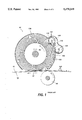
- FIG. 1 is an elevational view of prior art using an auger waste removal system
- FIG. 2 is an elevational view of the present invention using an air waste removal system for the detoning roll
- FIG. 3 is a schematic illustration of a printing apparatus incorporating the inventive features of the present invention.
- FIG. 3 depicts schematically the various components, thereof.
- like reference numerals will be employed throughout to designate identical elements.
- the flexible conductive cleaner brush apparatus of the present invention is particularly well adapted for use in an electrophotographic printing machine, it should become evident from the following discussion, that it is equally well suited for use in other applications and is not necessarily limited to the particular embodiment shown herein.
- a reproduction machine in which the present invention finds advantageous use, has a photoreceptor belt 10, having a photoconductive (or imaging) surface 11.
- the photoreceptor belt 10 moves in the direction of arrow 12 to advance excessive portions of the belt 10 sequentially through the various processing stations disposed about the path of movement thereof.
- the belt 10 is entrained about a stripping roller 14, a tension roller 16, and a drive roller 20.
- Drive roller 20 is coupled to a motor 21 by suitable means such as a belt drive.
- the belt 10 is maintained in tension by a pair of springs (not shown) resiliently urging tension roller 16 against the belt 10 with the desired spring force.
- Both stripping roller 14 and tension roller 16 are rotatably mounted. These rollers are idlers which rotate freely as the belt 10 moves in the direction of arrow 12.
- a corona device 22 charges a portion of the photoreceptor belt 10 to a relatively high, substantially uniform potential, either positive or negative.
- an original document is positioned face down on a transparent platen 30 for illumination with flash lamps 32.
- Light rays reflected from the original document are reflected through a lens 33 and projected onto the charged portion of the photoreceptor belt 10 to selectively dissipate the charge thereon.
- This records an electrostatic latent image on the belt which corresponds to the informational area contained within the original document.
- a laser may be provided to imagewise discharge the photoreceptor in accordance with stored electronic information.
- the belt 10 advances the electrostatic latent image to develop station C.
- developer housing 34 or 36 is brought into contact with the belt 10 for the purpose of developing the electrostatic latent image.
- Housings 34 and 36 may be moved into and out of developing position with corresponding cams 38 and 40, which are selectively driven by motor 21.
- Each developer housing 34 and 36 supports a developing system such as magnetic brush rolls 42 and 44, which provides a rotating magnetic member to advance developer mix (i.e. carrier beads and toner) into contact with the electrostatic latent image.
- developer mix i.e. carrier beads and toner
- the electrostatic latent image attracts toner particles from the carrier beads, thereby forming toner powder images on the photoreceptor belt 10. If two colors of developer material are not required, the second developer housing may be omitted.
- the photoreceptor belt 10 then advances the developed latent image to transfer station D.
- a sheet of support material such as paper copy sheets is advanced into contact with the developed latent images on the belt 10.
- a corona generating device 46 charges the copy sheet to the proper potential so that it becomes tacked to the photoreceptor belt 10 and the toner powder image is attracted from the photoreceptor belt 10 to the sheet.
- the corona generator 48 charges the copy sheet to an opposite polarity to detack the copy sheet from the belt 10, whereupon the sheet is stripped from the belt 10 at stripping roller 14.
- Sheets of support material 49 are advanced to transfer station D from a supply tray 50. Sheets are fed from tray 50, with sheet feeder 52, and advanced to transfer station D along conveyor 56.
- Fusing station E includes a fuser assembly indicated generally by the reference numeral 70, which permanently affixes the transfer toner powder images to the sheets.
- the fuser assembly 70 includes a heated fuser roller 72 adapted to be pressure engaged with a backup roller 74 with the toner powder images contacting the fuser roller 72. In this manner, the toner powder image is permanently affixed to the sheet, and such sheets are directed via a chute 62 to an output 80 or finisher.
- Residual particles, remaining on the photoreceptor belt 10 after each copy is made, may be removed at cleaning station F.
- the cleaning apparatus of the present invention is represented by the reference numeral 92 which will be described in greater detail in FIG. 2. Removed residual particles may also be stored for disposal.
- a backup roll 90 is provided as support to the photoreceptor belt 10 during the cleaning phase of the xerographic process.
- a machine controller 96 is preferably a known programmable controller or combination of controllers, which conventionally control all the machine steps and functions described above.
- the controller 96 is responsive to a variety of sensing devices to enhance control of the machine, and also provides connection diagnostic operations to a user interface (not shown) where required.
- a reproduction machine in accordance with the present invention may be any of several well known devices. Variations may be expected in specific electrophotographic processing, paper handling and control arrangements without effecting the present invention. However, it is believed that the foregoing description is sufficient for purposes of the present application to illustrate the general operation of an electrophotographic printing machine which exemplifies one type of apparatus employing the present invention therein.
- FIG. 1 shows an elevational view of the prior art using an auger waste removal system for the detoning roll.
- An electrostatic brush 100 rotating in the direction of arrow 98, inside a housing 130, cleans the imaging surface 11 of the photoreceptor 10.
- the residual particles 140 i.e. toner particles and other debris
- the detoning roll 110 rotating in the direction of arrow 109, attracts the charged particles 140 from the electrostatic brush fibers.
- a scraping blade 115 contacts the surface of the detoning roll 110 removing the residual particles 140 therefrom.
- the scraping blade 115 is positioned relative to the detoning roll 110 and the auger 120 such that the residual particles 140 removed by the blade 115 from the detoning roll surface, cascade over the blade surface down into the auger 120.
- the auger 120 rotating in the direction of arrow 119, transports the residual particles 140 to a waste toner container (not shown).
- the rotation of the auger 120 generates heat. This heat causes the toner particles to become soft, "blocking" the auger's rotation creating an unreliable waste removal system. (This "blocking" often causes a breakdown of the augering system.)
- FIG. 2 shows an elevational view of a brush cleaner with the present invention of an air waste removal system for the detoning roll.
- the present invention uses an electrically biased detone roll 110 for detoning a brush cleaner 100 and then uses air, to transport the waste removed from the detone roll 110, rather than an augering system.
- the cleaning system has a rotating electrostatic brush 100 with brush fibers extending radially from a center core.
- the rotating brush fibers contact the photoreceptor 10, causing a flicking action as the fibers leave the photoreceptor 10 that releases particles 140 therein, creating a powder cloud.
- a powder cloud vacuum port allows air flow, created by a vacuum 185, to enter the brush housing 131.
- the particles 140 released from the fibers are carried away by the air flow to the waste toner exhaust chamber 180 by an air channel 135 in the housing. This channel 135 is separated from the remainder of the housing by a dividing wall 136 containing the rotating brush 100.
- the brush fibers rebound from contact with the flicker bar 150 (i.e. mechanical detoning), creating a moving node affect releasing loosely held particles from the fibers into the air stream.
- This nodal affect allows air to move the residual particles 140 released from the fibers away from the brush fibers toward the waste toner chamber 180, where the particles 140 are then sent to a waste toner bottle (not shown).
- Adjacent to the flicker bar 150 is a vacuum throat 160 that the air flow entrained with toner and other waste particles (i.e. Kaolin, paper, debris, etc.) passes through to the waste toner exhaust chamber 180.
- a biased detone roll 110 rotating in the clockwise direction indicated by arrow 109, further cleans the brush fibers rebounding from contact with the flicker bar 150.
- the biased detone roll 110 attracts toner particles 140 electrostatically held from the brush fibers onto the detoning roll surface.
- a detone roll scraper 175 e.g. stainless steel blade
- the scraper 175 contacts the detone roll surface using a chiseling action to remove the residual particles from the detoning surface.
- On opposite sides of the detoning roll 110 are air channels 190, 195 to carry the dislodged toner particles 140 toward the waste toner exhaust chamber 180 by the air flow, created by a vacuum 185.
- the waste particles are later deposited into a waste container (not shown).
- the air channels 190, 195 are openings on either side of the detone roll 110.
- the detone roll scraper 175 is designed to also create a baffle. Only the scraper portion of the scraper/baffle is in contact with the detoner roll 110.
- One air channel 195 is formed between the scraper/baffle 175 and the flicker bar 150.
- the other air channel 190 is formed between the arcuate surface of the detoning roll 110 and the inside surface of the housing wall.
- the brush fibers release any remaining particles 140 as the brush fibers are released from contact with the rotating biased detone roll 110.
- the particles chiseled from the detone roll surface cascade into the air flow (i.e. air stream) that passes through air channel 195.
- the particles remaining in the brush fibers, after passing the detoning roll 110, are mechanically flicked from the detoning roll 110 into the air channel 190.
- the airflow created by the vacuum through these air channels 190, 195 carry the particles to the waste toner exhaust chamber 180.
- the air assist for the detoning roll, of the present invention removes the need for an augering system, which simplifies the cleaner configuration but, also helps keep the xerographic cavity cooler with the air flow.
- the air also aids in keeping the dirt levels lower since the cleaner is under a negative pressure and toner is not allowed to powder cloud and leave the cleaner.
- the present invention provides an air waste removal system to remove particles removed from the detoning roll.
- the toner is scraped from the detone rolls using a blade that allows the toner and waste particles to cascade into the air streams created by the air channels (or ports) on either side of the detone roll.
- the air waste removal system eliminates the augering system and it's unreliability. Also with the use of air system instead of an auger the xerographic cavity is cooler.
Landscapes
- Physics & Mathematics (AREA)
- General Physics & Mathematics (AREA)
- Life Sciences & Earth Sciences (AREA)
- Engineering & Computer Science (AREA)
- Environmental & Geological Engineering (AREA)
- Sustainable Development (AREA)
- Cleaning In Electrography (AREA)
Abstract
Description
Claims (16)
Priority Applications (1)
| Application Number | Priority Date | Filing Date | Title |
|---|---|---|---|
| US08/218,922 US5479249A (en) | 1994-03-28 | 1994-03-28 | Brush cleaner with roll detoning and air waste removal |
Applications Claiming Priority (1)
| Application Number | Priority Date | Filing Date | Title |
|---|---|---|---|
| US08/218,922 US5479249A (en) | 1994-03-28 | 1994-03-28 | Brush cleaner with roll detoning and air waste removal |
Publications (1)
| Publication Number | Publication Date |
|---|---|
| US5479249A true US5479249A (en) | 1995-12-26 |
Family
ID=22817028
Family Applications (1)
| Application Number | Title | Priority Date | Filing Date |
|---|---|---|---|
| US08/218,922 Expired - Fee Related US5479249A (en) | 1994-03-28 | 1994-03-28 | Brush cleaner with roll detoning and air waste removal |
Country Status (1)
| Country | Link |
|---|---|
| US (1) | US5479249A (en) |
Cited By (10)
| Publication number | Priority date | Publication date | Assignee | Title |
|---|---|---|---|---|
| US5587781A (en) * | 1995-12-01 | 1996-12-24 | Xerox Corporation | Optimizing electrostatic brush interferences for increased detoning efficiency |
| US20010026380A1 (en) * | 2000-03-23 | 2001-10-04 | Ricoh Company, Ltd. | Image reading device |
| US6453147B1 (en) * | 2000-08-16 | 2002-09-17 | Nexpress Solutions Llc | Dust control in conductive-core fiber brush cleaning systems using self-generated air flow |
| US6754466B1 (en) * | 2003-01-08 | 2004-06-22 | Xerox Corporation | Toner removal apparatus for copier or printer |
| US20040265007A1 (en) * | 2003-06-26 | 2004-12-30 | Fuji Xerox Co., Ltd. | Electrically conductive member, unit for cleaning image holding member, process cartridge and image forming apparatus |
| US20060285899A1 (en) * | 2005-06-20 | 2006-12-21 | Xerox Corporation | Waste toner vibration device |
| US20070025785A1 (en) * | 2005-07-27 | 2007-02-01 | Brother Kogyo Kabushiki Kaisha | Cleaning member for photosensitive drum |
| JP2014164132A (en) * | 2013-02-25 | 2014-09-08 | Ricoh Co Ltd | Cleaning device, process cartridge, and image forming apparatus |
| JP2018197826A (en) * | 2017-05-24 | 2018-12-13 | 京セラドキュメントソリューションズ株式会社 | Image forming apparatus |
| US10969728B2 (en) | 2016-10-07 | 2021-04-06 | Ideego Gmbh | Cleaning device for the surface of a cylinder of a printer and/or copier |
Citations (4)
| Publication number | Priority date | Publication date | Assignee | Title |
|---|---|---|---|---|
| US3917397A (en) * | 1973-04-02 | 1975-11-04 | Minolta Camera Kk | Mechanism for removing residual toner from electrostatic copier drum |
| US4304026A (en) * | 1979-10-01 | 1981-12-08 | Xerox Corporation | Cleaning apparatus for a xerographic reproduction machine |
| US4989047A (en) * | 1989-12-11 | 1991-01-29 | Xerox Corporation | Cleaning apparatus for the reduction of agglomeration-caused spotting |
| US5381218A (en) * | 1993-11-22 | 1995-01-10 | Xerox Corporation | Conductive cleaning brush belt and detoning thereof |
-
1994
- 1994-03-28 US US08/218,922 patent/US5479249A/en not_active Expired - Fee Related
Patent Citations (5)
| Publication number | Priority date | Publication date | Assignee | Title |
|---|---|---|---|---|
| US3917397A (en) * | 1973-04-02 | 1975-11-04 | Minolta Camera Kk | Mechanism for removing residual toner from electrostatic copier drum |
| US4304026A (en) * | 1979-10-01 | 1981-12-08 | Xerox Corporation | Cleaning apparatus for a xerographic reproduction machine |
| US4989047A (en) * | 1989-12-11 | 1991-01-29 | Xerox Corporation | Cleaning apparatus for the reduction of agglomeration-caused spotting |
| US5031000A (en) * | 1989-12-11 | 1991-07-09 | Xerox Corporation | Cleaning apparatus for the reduction of agglomeration-caused spotting |
| US5381218A (en) * | 1993-11-22 | 1995-01-10 | Xerox Corporation | Conductive cleaning brush belt and detoning thereof |
Non-Patent Citations (2)
| Title |
|---|
| IBM Tech. Disclosure Bulletin; vol. 19, No. 3, Aug. 1976, Boman, et al., "Cleaning Station for an Electrographic Copying Machine", pp. 808-809. |
| IBM Tech. Disclosure Bulletin; vol. 19, No. 3, Aug. 1976, Boman, et al., Cleaning Station for an Electrographic Copying Machine , pp. 808 809. * |
Cited By (14)
| Publication number | Priority date | Publication date | Assignee | Title |
|---|---|---|---|---|
| US5587781A (en) * | 1995-12-01 | 1996-12-24 | Xerox Corporation | Optimizing electrostatic brush interferences for increased detoning efficiency |
| US7212320B2 (en) * | 2000-03-23 | 2007-05-01 | Ricoh Company, Ltd. | Image reading device |
| US20010026380A1 (en) * | 2000-03-23 | 2001-10-04 | Ricoh Company, Ltd. | Image reading device |
| US6453147B1 (en) * | 2000-08-16 | 2002-09-17 | Nexpress Solutions Llc | Dust control in conductive-core fiber brush cleaning systems using self-generated air flow |
| US6754466B1 (en) * | 2003-01-08 | 2004-06-22 | Xerox Corporation | Toner removal apparatus for copier or printer |
| US20040131404A1 (en) * | 2003-01-08 | 2004-07-08 | Xerox Corporation | Toner removal apparatus for copier or printer |
| US20040265007A1 (en) * | 2003-06-26 | 2004-12-30 | Fuji Xerox Co., Ltd. | Electrically conductive member, unit for cleaning image holding member, process cartridge and image forming apparatus |
| US7103304B2 (en) * | 2003-06-26 | 2006-09-05 | Fuji Xerox Co., Ltd. | Electrically conductive member, unit for cleaning image holding member, process cartridge and image forming apparatus |
| US20060285899A1 (en) * | 2005-06-20 | 2006-12-21 | Xerox Corporation | Waste toner vibration device |
| US20070025785A1 (en) * | 2005-07-27 | 2007-02-01 | Brother Kogyo Kabushiki Kaisha | Cleaning member for photosensitive drum |
| US7689155B2 (en) * | 2005-07-27 | 2010-03-30 | Brother Kogyo Kabushiki Kaisha | Cleaning member for photosensitive drum |
| JP2014164132A (en) * | 2013-02-25 | 2014-09-08 | Ricoh Co Ltd | Cleaning device, process cartridge, and image forming apparatus |
| US10969728B2 (en) | 2016-10-07 | 2021-04-06 | Ideego Gmbh | Cleaning device for the surface of a cylinder of a printer and/or copier |
| JP2018197826A (en) * | 2017-05-24 | 2018-12-13 | 京セラドキュメントソリューションズ株式会社 | Image forming apparatus |
Similar Documents
| Publication | Publication Date | Title |
|---|---|---|
| EP0432453B1 (en) | Cleaning apparatus for the reduction of agglomeration caused spotting | |
| US4819026A (en) | Cleaning apparatus for a charge retentive surface | |
| US5028959A (en) | Vacuum collection system for dirt management | |
| EP0366426B1 (en) | Electrophotographic device having an a.c. biased cleaning member | |
| US5257079A (en) | Electrostatic brush cleaner with a secondary cleaner | |
| US3590412A (en) | Brush cleaning device for electrostatic machines | |
| US4435073A (en) | Toner removal apparatus | |
| CA2132243C (en) | Lubrication of a detoning roll | |
| US5444522A (en) | Replaceable cleaner subsystem that prevents particle spillage | |
| US5479249A (en) | Brush cleaner with roll detoning and air waste removal | |
| US4145137A (en) | Electrophotographic reproducing machine blade cleaning apparatus | |
| EP0346454B1 (en) | Dual purpose cleaning apparatus | |
| US5315358A (en) | Flicker bar with an integral air channel | |
| EP0322231B1 (en) | Rotating vane toner transport for blade cleaning on horizontal surfaces | |
| US5381218A (en) | Conductive cleaning brush belt and detoning thereof | |
| US6169872B1 (en) | Electrostatic cleaning belt brush | |
| US5341201A (en) | Xerographic brush cleaner detoner | |
| US5210582A (en) | Stretchable cleaner band disturber | |
| US5357328A (en) | Ground strip brush cleaner | |
| US5597419A (en) | Slow brush rotation in standby to avoid brush flat spots | |
| US5241352A (en) | Air detoned cleaner brush | |
| US6144834A (en) | Self biasing, extended nip electrostatic cleaner | |
| JPH05142971A (en) | Copying device | |
| JPH07253741A (en) | Image-forming device | |
| JPH04219779A (en) | Cleaner device for color electrophotography |
Legal Events
| Date | Code | Title | Description |
|---|---|---|---|
| AS | Assignment |
Owner name: XEROX CORPORATION, CONNECTICUT Free format text: ASSIGNMENT OF ASSIGNORS INTEREST;ASSIGNORS:JUGLE, KIP L.;LUNDY, DOUGLAS A.;REEL/FRAME:006940/0543 Effective date: 19940323 |
|
| FPAY | Fee payment |
Year of fee payment: 4 |
|
| AS | Assignment |
Owner name: BANK ONE, NA, AS ADMINISTRATIVE AGENT, ILLINOIS Free format text: SECURITY INTEREST;ASSIGNOR:XEROX CORPORATION;REEL/FRAME:013153/0001 Effective date: 20020621 |
|
| FPAY | Fee payment |
Year of fee payment: 8 |
|
| AS | Assignment |
Owner name: JPMORGAN CHASE BANK, AS COLLATERAL AGENT, TEXAS Free format text: SECURITY AGREEMENT;ASSIGNOR:XEROX CORPORATION;REEL/FRAME:015134/0476 Effective date: 20030625 Owner name: JPMORGAN CHASE BANK, AS COLLATERAL AGENT,TEXAS Free format text: SECURITY AGREEMENT;ASSIGNOR:XEROX CORPORATION;REEL/FRAME:015134/0476 Effective date: 20030625 |
|
| REMI | Maintenance fee reminder mailed | ||
| AS | Assignment |
Owner name: XEROX CORPORATION, NEW YORK Free format text: RELEASE BY SECURED PARTY;ASSIGNOR:JP MORGAN CHASE BANK, NA;REEL/FRAME:020031/0840 Effective date: 20061204 |
|
| AS | Assignment |
Owner name: XEROX CORPORATION, NEW YORK Free format text: RELEASE BY SECURED PARTY;ASSIGNOR:BANK ONE, NA;REEL/FRAME:020045/0538 Effective date: 20030625 |
|
| LAPS | Lapse for failure to pay maintenance fees | ||
| STCH | Information on status: patent discontinuation |
Free format text: PATENT EXPIRED DUE TO NONPAYMENT OF MAINTENANCE FEES UNDER 37 CFR 1.362 |
|
| FP | Lapsed due to failure to pay maintenance fee |
Effective date: 20071226 |
|
| AS | Assignment |
Owner name: XEROX CORPORATION, CONNECTICUT Free format text: RELEASE BY SECURED PARTY;ASSIGNOR:JPMORGAN CHASE BANK, N.A. AS SUCCESSOR-IN-INTEREST ADMINISTRATIVE AGENT AND COLLATERAL AGENT TO JPMORGAN CHASE BANK;REEL/FRAME:066728/0193 Effective date: 20220822 |