US5475564A - CPU heat sink holding-down device - Google Patents
CPU heat sink holding-down device Download PDFInfo
- Publication number
- US5475564A US5475564A US08/359,482 US35948294A US5475564A US 5475564 A US5475564 A US 5475564A US 35948294 A US35948294 A US 35948294A US 5475564 A US5475564 A US 5475564A
- Authority
- US
- United States
- Prior art keywords
- cpu
- heat sink
- hanger
- holder
- vertical side
- Prior art date
- Legal status (The legal status is an assumption and is not a legal conclusion. Google has not performed a legal analysis and makes no representation as to the accuracy of the status listed.)
- Expired - Fee Related
Links
Images


Classifications
-
- H—ELECTRICITY
- H01—ELECTRIC ELEMENTS
- H01L—SEMICONDUCTOR DEVICES NOT COVERED BY CLASS H10
- H01L23/00—Details of semiconductor or other solid state devices
- H01L23/34—Arrangements for cooling, heating, ventilating or temperature compensation ; Temperature sensing arrangements
- H01L23/46—Arrangements for cooling, heating, ventilating or temperature compensation ; Temperature sensing arrangements involving the transfer of heat by flowing fluids
- H01L23/467—Arrangements for cooling, heating, ventilating or temperature compensation ; Temperature sensing arrangements involving the transfer of heat by flowing fluids by flowing gases, e.g. air
-
- H—ELECTRICITY
- H01—ELECTRIC ELEMENTS
- H01L—SEMICONDUCTOR DEVICES NOT COVERED BY CLASS H10
- H01L23/00—Details of semiconductor or other solid state devices
- H01L23/34—Arrangements for cooling, heating, ventilating or temperature compensation ; Temperature sensing arrangements
- H01L23/40—Mountings or securing means for detachable cooling or heating arrangements ; fixed by friction, plugs or springs
- H01L23/4093—Snap-on arrangements, e.g. clips
-
- H—ELECTRICITY
- H01—ELECTRIC ELEMENTS
- H01L—SEMICONDUCTOR DEVICES NOT COVERED BY CLASS H10
- H01L2924/00—Indexing scheme for arrangements or methods for connecting or disconnecting semiconductor or solid-state bodies as covered by H01L24/00
- H01L2924/0001—Technical content checked by a classifier
- H01L2924/0002—Not covered by any one of groups H01L24/00, H01L24/00 and H01L2224/00
-
- Y—GENERAL TAGGING OF NEW TECHNOLOGICAL DEVELOPMENTS; GENERAL TAGGING OF CROSS-SECTIONAL TECHNOLOGIES SPANNING OVER SEVERAL SECTIONS OF THE IPC; TECHNICAL SUBJECTS COVERED BY FORMER USPC CROSS-REFERENCE ART COLLECTIONS [XRACs] AND DIGESTS
- Y10—TECHNICAL SUBJECTS COVERED BY FORMER USPC
- Y10T—TECHNICAL SUBJECTS COVERED BY FORMER US CLASSIFICATION
- Y10T24/00—Buckles, buttons, clasps, etc.
- Y10T24/45—Separable-fastener or required component thereof [e.g., projection and cavity to complete interlock]
- Y10T24/45225—Separable-fastener or required component thereof [e.g., projection and cavity to complete interlock] including member having distinct formations and mating member selectively interlocking therewith
- Y10T24/45471—Projection having movable connection between components thereof or variable configuration
- Y10T24/45524—Projection having movable connection between components thereof or variable configuration including resiliently biased projection component or surface segment
- Y10T24/45529—Requiring manual force applied against bias to interlock or disengage
Definitions
- the present invention relates to a CPU heat sink holding down device for fastening a heat sink to a CPU holder to hold down a CPU by a movable loop-like hanger and a fixed loop-like hanger.
- the heat sink has a fixed loop-like hanger at one side and a movable loop-like hanger at an opposite side for fastening to respective retainer rods at two opposite side of any of a variety of CPU holder.
- the second loop-like hanger is relatively smaller than the fixed loop-like hanger, and can be turned about and moved along a transverse screw rod, and therefore the second loop-like hanger can be conveniently adjusted to the operative position and secured to the corresponding retainer rod on the CPU holder.
- a curved spring plate is coupled to the movable loop-like hanger and acted as a lever for lifting the movable loop-like hanger from the corresponding retainer rod on the CPU holder during a repair or maintenance work.
- FIG. 1 is an elevational view of a CPU heat sink holding-down device according to the present invention
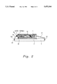
- FIG. 2 is a side view in section of the CPU heat sink holding-down device shown in FIG. 1;
- FIG. 3 is a top plain view of FIG. 1, showing the movable loop-like hanger moved along the screw rod;
- FIG. 4A shows the curved spring plate served as a first class lever and operated
- FIG. 4B shows the curved spring plate served as a second class lever and operated.
- a CPU heat sink holding-down device in accordance with the present invention is generally comprised of a CPU holder 3, a CPU 2 mounted on the CPU holder 3, and a heat sink 1 fastened to the CPU holder 3 to hold down the CPU 2.
- the heat sink 1 comprises a plurality of heat dissipating holes 11 spaced around the vertical sides thereof, a fixed loop-like hanger 17 pivotably disposed at one vertical side thereof, two locating bars 13 and 14 extended out of an opposite vertical side thereof, a screw rod 15 connected between the locating bars 13 and 14, and a movable loop-like hanger 16 turned about the screw rod 15.
- a fan 12 is disposed within the heat sink 1 and controlled to cause currents of air for cooling.
- the CPU holder 3 has two retainer rods 31 at two opposite vertical sides thereof.
- the fixed and movable loop-like hangers 17 and 16 are respectively hung on the retainer rods 31 of the CPU holder 3 to hold down the heat sink 1.
- the movable loop-like hanger 16 has a fastening portion 161, which is releasably fastened to one retainer rod 31, mounted with a curved spring plate 162.
- the locating bars 13 and 14 have a respective forked rear end 131 or 141 turned at right angles and releasably mounted on a respective support 18 inside the heat sink 1.
- the movable loop-like hanger 16 can be moved along the screw rod 15 to the effective position aiming at the corresponding retainer rod 31 on the CPU holder3.
- the curved spring plate 162 can be used as a lever to lift the fastening portion 161 of the movable loop-like hanger 16 from the corresponding retainer rod 31.
- the curved spring plate 162 acts as a first class lever.
- the curved spring plate 162 acts as a second class lever.
Landscapes
- Physics & Mathematics (AREA)
- Condensed Matter Physics & Semiconductors (AREA)
- General Physics & Mathematics (AREA)
- Engineering & Computer Science (AREA)
- Computer Hardware Design (AREA)
- Microelectronics & Electronic Packaging (AREA)
- Power Engineering (AREA)
- Cooling Or The Like Of Electrical Apparatus (AREA)
Abstract
A CPU heat sink holding-down device including a CPU holder, a CPU mounted on the CPU holder, and a heat sink fastened to the CPU holder to hold down the CPU, wherein the heat sink has a fixed loop-like hanger pivotably disposed at one vertical side thereof and hung on a first retainer rod at one vertical side of the CPU holder, two locating bar extended out of an opposite vertical side thereof, a screw rod connected between the locating bars, a movable loop-like hanger turned about said screw rod and hung on a second retainer rod at an opposite vertical side of the CPU holder, and a curved spring plate connected to the movable loop-like hanger for lifting the movable loop-like hanger from the second retainer rod.
Description
The present invention relates to a CPU heat sink holding down device for fastening a heat sink to a CPU holder to hold down a CPU by a movable loop-like hanger and a fixed loop-like hanger.
Various computers are well known, and intensively used in every field to replace a variety of complicated jobs. In a computer system, the CPU is one of the most import part. During the operation of a computer system, the CPU will release heat. If heat cannot be quickly carried away, the operation of the CPU and the nearby electronic components will be affected, causing operation errors. Heat sinks are commonly used and mounted on the CPU holder to hold down the CPU. Regular heat sinks generally have fastening devices for fastening to the CPU holder. However, these fastening devices are specifically designed for specific CPU holders, i.e., they are not suitable for all CPU holders.
According to one aspect of the present invention, the heat sink has a fixed loop-like hanger at one side and a movable loop-like hanger at an opposite side for fastening to respective retainer rods at two opposite side of any of a variety of CPU holder. The second loop-like hanger is relatively smaller than the fixed loop-like hanger, and can be turned about and moved along a transverse screw rod, and therefore the second loop-like hanger can be conveniently adjusted to the operative position and secured to the corresponding retainer rod on the CPU holder.
According to another aspect of the present invention, a curved spring plate is coupled to the movable loop-like hanger and acted as a lever for lifting the movable loop-like hanger from the corresponding retainer rod on the CPU holder during a repair or maintenance work.
FIG. 1 is an elevational view of a CPU heat sink holding-down device according to the present invention;
FIG. 2 is a side view in section of the CPU heat sink holding-down device shown in FIG. 1;
FIG. 3 is a top plain view of FIG. 1, showing the movable loop-like hanger moved along the screw rod;
FIG. 4A shows the curved spring plate served as a first class lever and operated; and
FIG. 4B shows the curved spring plate served as a second class lever and operated.
Referring to FIG. 1, a CPU heat sink holding-down device in accordance with the present invention is generally comprised of a CPU holder 3, a CPU 2 mounted on the CPU holder 3, and a heat sink 1 fastened to the CPU holder 3 to hold down the CPU 2. The heat sink 1 comprises a plurality of heat dissipating holes 11 spaced around the vertical sides thereof, a fixed loop-like hanger 17 pivotably disposed at one vertical side thereof, two locating bars 13 and 14 extended out of an opposite vertical side thereof, a screw rod 15 connected between the locating bars 13 and 14, and a movable loop-like hanger 16 turned about the screw rod 15. A fan 12 is disposed within the heat sink 1 and controlled to cause currents of air for cooling. The CPU holder 3 has two retainer rods 31 at two opposite vertical sides thereof. When the heat sink 1 is placed on the CPU2 above the CPU holder 3, the fixed and movable loop- like hangers 17 and 16 are respectively hung on the retainer rods 31 of the CPU holder 3 to hold down the heat sink 1. The movable loop-like hanger 16 has a fastening portion 161, which is releasably fastened to one retainer rod 31, mounted with a curved spring plate 162.
Referring to FIG. 2, the locating bars 13 and 14 have a respective forked rear end 131 or 141 turned at right angles and releasably mounted on a respective support 18 inside the heat sink 1.
Referring to FIG. 3, the movable loop-like hanger 16 can be moved along the screw rod 15 to the effective position aiming at the corresponding retainer rod 31 on the CPU holder3.
Referring to FIG. 4A and 4B, the curved spring plate 162 can be used as a lever to lift the fastening portion 161 of the movable loop-like hanger 16 from the corresponding retainer rod 31. In FIG. 4A, the curved spring plate 162 acts as a first class lever. In FIG. 4B, the curved spring plate 162 acts as a second class lever.
While only one embodiment of the present invention has been shown and described, it will be understood that various modifications and changes could be made without departing from the spirit and scope of the invention.
Claims (1)
1. A CPU heat sink holding-down device comprising a CPU holder, a CPU mounted on said CPU holder, and a heat sink fastened to said CPU holder to hold down said CPU, wherein said heat sink comprises a fixed loop-like hanger pivotably disposed at one vertical side thereof hung on a first retainer rod at one vertical side of said CPU holder, two locating bars extended out of an opposite vertical side of said heat sink, a screw rod connected between said locating bars, a movable loop-like hanger turned about said screw rod and hung on a second retainer rod at an opposite vertical side of said CPU holder, and a curved spring plate connected to said movable loop-like hanger for lifting said movable loop-like hanger from said second retainer rod.
Priority Applications (1)
| Application Number | Priority Date | Filing Date | Title |
|---|---|---|---|
| US08/359,482 US5475564A (en) | 1994-12-20 | 1994-12-20 | CPU heat sink holding-down device |
Applications Claiming Priority (1)
| Application Number | Priority Date | Filing Date | Title |
|---|---|---|---|
| US08/359,482 US5475564A (en) | 1994-12-20 | 1994-12-20 | CPU heat sink holding-down device |
Publications (1)
| Publication Number | Publication Date |
|---|---|
| US5475564A true US5475564A (en) | 1995-12-12 |
Family
ID=23413987
Family Applications (1)
| Application Number | Title | Priority Date | Filing Date |
|---|---|---|---|
| US08/359,482 Expired - Fee Related US5475564A (en) | 1994-12-20 | 1994-12-20 | CPU heat sink holding-down device |
Country Status (1)
| Country | Link |
|---|---|
| US (1) | US5475564A (en) |
Cited By (27)
| Publication number | Priority date | Publication date | Assignee | Title |
|---|---|---|---|---|
| US5542468A (en) * | 1995-06-28 | 1996-08-06 | Lin; Chuen-Sheng | CPU heat dissipator hook-up apparatus |
| US5581442A (en) * | 1995-06-06 | 1996-12-03 | Wakefield Engineering, Inc. | Spring clip for clamping a heat sink module to an electronic module |
| US5615084A (en) * | 1995-06-30 | 1997-03-25 | International Business Machines Corporation | Enhanced flow distributor for integrated circuit spot coolers |
| US5621244A (en) * | 1994-05-16 | 1997-04-15 | Lin; Shih-Jen | Fin assembly for an integrated circuit |
| US5650912A (en) * | 1992-05-28 | 1997-07-22 | Fujitu Limited | Heat sink for cooling a heat producing element and application |
| WO1997031236A1 (en) | 1996-02-22 | 1997-08-28 | Lemont Aircraft Corporation | Active heat sink structure with flow augmenting rings and method for removing heat |
| US5678627A (en) * | 1996-01-03 | 1997-10-21 | Lee; Richard | CPU heat sink mounting structure |
| GB2313712A (en) * | 1996-05-30 | 1997-12-03 | Ming Der Chiou | Mounting heat sinks |
| US5704419A (en) * | 1995-06-30 | 1998-01-06 | International Business Machines Corporation | Air flow distribution in integrated circuit spot coolers |
| US5737171A (en) * | 1996-07-15 | 1998-04-07 | International Business Machines Corporation | Switched management of thermal impedence to reduce temperature excursions |
| US5930116A (en) * | 1998-06-12 | 1999-07-27 | Harman International Industries, Incorporated | Integrated clamping mechanism |
| US6381836B1 (en) * | 1998-02-23 | 2002-05-07 | Intel Corporation | Clip and pin field for IC packaging |
| US6407919B1 (en) * | 2000-12-18 | 2002-06-18 | Fargo Chou | Structure of computer CPU heat dissipation module |
| US6600654B2 (en) | 2001-06-29 | 2003-07-29 | International Business Machines Corporation | System for securing a processor socket |
| US6606244B1 (en) * | 1999-09-10 | 2003-08-12 | Saint Song Corp. | Pointing device having computer host |
| US20050174739A1 (en) * | 2004-02-07 | 2005-08-11 | Hon Hai Precision Industry Co., Ltd. | Heat sink mounting device |
| US20050225946A1 (en) * | 2003-04-11 | 2005-10-13 | Fan Chen L | Locking device for heat sink |
| US20080056844A1 (en) * | 2000-03-10 | 2008-03-06 | Southco, Inc. | Floating captive screw |
| US7342796B2 (en) | 2005-06-03 | 2008-03-11 | Southco, Inc. | Captive shoulder nut assembly |
| US7344345B2 (en) | 2004-05-27 | 2008-03-18 | Southco, Inc. | Captive shoulder nut having spring tie-down |
| US7367381B2 (en) | 1998-05-21 | 2008-05-06 | Nidec Copal Corporation | Fan motor |
| US7584780B1 (en) | 1998-12-09 | 2009-09-08 | Lemont Aircraft Corporation | Active heat sink structure with flow augmenting rings and method for removing heat |
| US20100258282A1 (en) * | 2009-04-10 | 2010-10-14 | Fu Zhun Precision Industry (Shen Zhen) Co., Ltd. | Heat dissipation device having fan holders |
| US20130108397A1 (en) * | 2011-10-27 | 2013-05-02 | Kunihiko NARUSE | Screw fall preventing structure |
| US20140215811A1 (en) * | 2013-02-06 | 2014-08-07 | Foshan KonFonYon Technology Co., Ltd. | Led pressure-installing structure |
| US20150082823A1 (en) * | 2012-04-27 | 2015-03-26 | Daikin Industries, Ltd. | Cooler, electrical component unit, and refrigeration apparatus |
| CN109623865A (en) * | 2018-11-26 | 2019-04-16 | 华中科技大学 | Cpu heat fixture and mounting device suitable for industrial robot |
Citations (6)
| Publication number | Priority date | Publication date | Assignee | Title |
|---|---|---|---|---|
| US4589170A (en) * | 1983-06-14 | 1986-05-20 | Springfast Limited | Sink fasteners |
| US5208731A (en) * | 1992-01-17 | 1993-05-04 | International Electronic Research Corporation | Heat dissipating assembly |
| US5357404A (en) * | 1991-11-18 | 1994-10-18 | The Whitaker Corporation | EMI shield, and assembly using same |
| US5371652A (en) * | 1993-11-15 | 1994-12-06 | Thermalloy, Inc. | Spring clamp assembly with electrically insulating shoe |
| US5386338A (en) * | 1993-12-20 | 1995-01-31 | Thermalloy, Inc. | Heat sink attachment assembly |
| US5430610A (en) * | 1994-06-15 | 1995-07-04 | Hung; Chin-Ping | Separable positioning device for the heat sink on computer chips |
-
1994
- 1994-12-20 US US08/359,482 patent/US5475564A/en not_active Expired - Fee Related
Patent Citations (6)
| Publication number | Priority date | Publication date | Assignee | Title |
|---|---|---|---|---|
| US4589170A (en) * | 1983-06-14 | 1986-05-20 | Springfast Limited | Sink fasteners |
| US5357404A (en) * | 1991-11-18 | 1994-10-18 | The Whitaker Corporation | EMI shield, and assembly using same |
| US5208731A (en) * | 1992-01-17 | 1993-05-04 | International Electronic Research Corporation | Heat dissipating assembly |
| US5371652A (en) * | 1993-11-15 | 1994-12-06 | Thermalloy, Inc. | Spring clamp assembly with electrically insulating shoe |
| US5386338A (en) * | 1993-12-20 | 1995-01-31 | Thermalloy, Inc. | Heat sink attachment assembly |
| US5430610A (en) * | 1994-06-15 | 1995-07-04 | Hung; Chin-Ping | Separable positioning device for the heat sink on computer chips |
Cited By (35)
| Publication number | Priority date | Publication date | Assignee | Title |
|---|---|---|---|---|
| US5650912A (en) * | 1992-05-28 | 1997-07-22 | Fujitu Limited | Heat sink for cooling a heat producing element and application |
| US6067227A (en) * | 1992-05-28 | 2000-05-23 | Fujitsu Limited | Heat sink for cooling a heat producing element and application |
| US5621244A (en) * | 1994-05-16 | 1997-04-15 | Lin; Shih-Jen | Fin assembly for an integrated circuit |
| US5581442A (en) * | 1995-06-06 | 1996-12-03 | Wakefield Engineering, Inc. | Spring clip for clamping a heat sink module to an electronic module |
| US5542468A (en) * | 1995-06-28 | 1996-08-06 | Lin; Chuen-Sheng | CPU heat dissipator hook-up apparatus |
| US5704419A (en) * | 1995-06-30 | 1998-01-06 | International Business Machines Corporation | Air flow distribution in integrated circuit spot coolers |
| US5615084A (en) * | 1995-06-30 | 1997-03-25 | International Business Machines Corporation | Enhanced flow distributor for integrated circuit spot coolers |
| US5678627A (en) * | 1996-01-03 | 1997-10-21 | Lee; Richard | CPU heat sink mounting structure |
| US5896917A (en) * | 1996-02-22 | 1999-04-27 | Lemont Aircraft Corporation | Active heat sink structure with flow augmenting rings and method for removing heat |
| WO1997031236A1 (en) | 1996-02-22 | 1997-08-28 | Lemont Aircraft Corporation | Active heat sink structure with flow augmenting rings and method for removing heat |
| GB2313712A (en) * | 1996-05-30 | 1997-12-03 | Ming Der Chiou | Mounting heat sinks |
| US5737171A (en) * | 1996-07-15 | 1998-04-07 | International Business Machines Corporation | Switched management of thermal impedence to reduce temperature excursions |
| US6381836B1 (en) * | 1998-02-23 | 2002-05-07 | Intel Corporation | Clip and pin field for IC packaging |
| US7367381B2 (en) | 1998-05-21 | 2008-05-06 | Nidec Copal Corporation | Fan motor |
| US5930116A (en) * | 1998-06-12 | 1999-07-27 | Harman International Industries, Incorporated | Integrated clamping mechanism |
| US7584780B1 (en) | 1998-12-09 | 2009-09-08 | Lemont Aircraft Corporation | Active heat sink structure with flow augmenting rings and method for removing heat |
| US6606244B1 (en) * | 1999-09-10 | 2003-08-12 | Saint Song Corp. | Pointing device having computer host |
| US20080056844A1 (en) * | 2000-03-10 | 2008-03-06 | Southco, Inc. | Floating captive screw |
| US8794889B2 (en) | 2000-03-10 | 2014-08-05 | Southco, Inc. | Floating captive screw |
| US6407919B1 (en) * | 2000-12-18 | 2002-06-18 | Fargo Chou | Structure of computer CPU heat dissipation module |
| US6600654B2 (en) | 2001-06-29 | 2003-07-29 | International Business Machines Corporation | System for securing a processor socket |
| US7106591B2 (en) | 2003-04-11 | 2006-09-12 | Hon Hai Precision Ind. Co., Ltd. | Locking device for heat sink |
| US20050225946A1 (en) * | 2003-04-11 | 2005-10-13 | Fan Chen L | Locking device for heat sink |
| US20050174739A1 (en) * | 2004-02-07 | 2005-08-11 | Hon Hai Precision Industry Co., Ltd. | Heat sink mounting device |
| US7344345B2 (en) | 2004-05-27 | 2008-03-18 | Southco, Inc. | Captive shoulder nut having spring tie-down |
| US7180744B2 (en) | 2004-07-02 | 2007-02-20 | Fu Zhun Precision Industry (Shenzhen) Co., Ltd. | Heat sink mounting device |
| US7342796B2 (en) | 2005-06-03 | 2008-03-11 | Southco, Inc. | Captive shoulder nut assembly |
| US20100258282A1 (en) * | 2009-04-10 | 2010-10-14 | Fu Zhun Precision Industry (Shen Zhen) Co., Ltd. | Heat dissipation device having fan holders |
| US20130108397A1 (en) * | 2011-10-27 | 2013-05-02 | Kunihiko NARUSE | Screw fall preventing structure |
| US8882424B2 (en) * | 2011-10-27 | 2014-11-11 | Konica Minolta Business Technologies, Inc. | Screw fall preventing structure |
| US20150082823A1 (en) * | 2012-04-27 | 2015-03-26 | Daikin Industries, Ltd. | Cooler, electrical component unit, and refrigeration apparatus |
| US9877410B2 (en) * | 2012-04-27 | 2018-01-23 | Daikin Industries, Ltd. | Cooler, electrical component unit, and refrigeration apparatus |
| US20140215811A1 (en) * | 2013-02-06 | 2014-08-07 | Foshan KonFonYon Technology Co., Ltd. | Led pressure-installing structure |
| CN109623865A (en) * | 2018-11-26 | 2019-04-16 | 华中科技大学 | Cpu heat fixture and mounting device suitable for industrial robot |
| CN109623865B (en) * | 2018-11-26 | 2020-11-17 | 华中科技大学 | CPU radiator anchor clamps and installation device suitable for industrial robot |
Similar Documents
| Publication | Publication Date | Title |
|---|---|---|
| US5475564A (en) | CPU heat sink holding-down device | |
| US5377745A (en) | Cooling device for central processing unit | |
| US5638258A (en) | CPU heat sink fastener | |
| US6183214B1 (en) | Cooling fan mounting arrangement | |
| JP3095802U (en) | Fixing device | |
| US20030034717A1 (en) | Computer case with an adjustable space | |
| US5771153A (en) | CPU heat dissipating apparatus | |
| US5678627A (en) | CPU heat sink mounting structure | |
| US2508974A (en) | Lantern holder | |
| US7637310B2 (en) | Heat dissipation device with fixtures for attachment of a fan | |
| US5828553A (en) | CPU heat sink fastener | |
| US6137683A (en) | Heat-dissipating device for an electronic component | |
| US5423375A (en) | CPU heat sink mounting structure | |
| US2912991A (en) | Article carrying bracket adapted for attachment to a crutch or the like | |
| US6404633B1 (en) | Securing equipment for a heat dissipater of CPU | |
| US2820377A (en) | Portable magnetic drill press | |
| US7471517B1 (en) | Heat sink retention module having force-adjustable wire modules | |
| US6532153B1 (en) | Heat sink mounting structure | |
| SE506201C2 (en) | Way and device for mounting a directional antenna in adjustable incline position | |
| US20040200600A1 (en) | Cpu radiator holding mechanism | |
| US20050183842A1 (en) | Fastening device for a radiator | |
| CN212287704U (en) | Clamping jaw capable of adjusting different clamping ranges | |
| US5664622A (en) | Heat sink with deformable hangers for mounting | |
| KR200201338Y1 (en) | Crane hook assistant unit | |
| US20030007324A1 (en) | Computer with thermal cooling and a thermal cooling system and method |
Legal Events
| Date | Code | Title | Description |
|---|---|---|---|
| REMI | Maintenance fee reminder mailed | ||
| LAPS | Lapse for failure to pay maintenance fees | ||
| FP | Lapsed due to failure to pay maintenance fee |
Effective date: 19991212 |
|
| STCH | Information on status: patent discontinuation |
Free format text: PATENT EXPIRED DUE TO NONPAYMENT OF MAINTENANCE FEES UNDER 37 CFR 1.362 |