US5412464A - Apparatus and method for monitoring losses in a branched optical fibre network - Google Patents
Apparatus and method for monitoring losses in a branched optical fibre network Download PDFInfo
- Publication number
- US5412464A US5412464A US07/949,846 US94984692A US5412464A US 5412464 A US5412464 A US 5412464A US 94984692 A US94984692 A US 94984692A US 5412464 A US5412464 A US 5412464A
- Authority
- US
- United States
- Prior art keywords
- branch lines
- optical
- main line
- branch
- optical fibre
- Prior art date
- Legal status (The legal status is an assumption and is not a legal conclusion. Google has not performed a legal analysis and makes no representation as to the accuracy of the status listed.)
- Expired - Lifetime
Links
Images

Classifications
-
- G—PHYSICS
- G01—MEASURING; TESTING
- G01M—TESTING STATIC OR DYNAMIC BALANCE OF MACHINES OR STRUCTURES; TESTING OF STRUCTURES OR APPARATUS, NOT OTHERWISE PROVIDED FOR
- G01M11/00—Testing of optical apparatus; Testing structures by optical methods not otherwise provided for
- G01M11/30—Testing of optical devices, constituted by fibre optics or optical waveguides
- G01M11/31—Testing of optical devices, constituted by fibre optics or optical waveguides with a light emitter and a light receiver being disposed at the same side of a fibre or waveguide end-face, e.g. reflectometers
- G01M11/3172—Reflectometers detecting the back-scattered light in the frequency-domain, e.g. OFDR, FMCW, heterodyne detection
Definitions
- This invention relates to detection and measurement of losses in a branched optical fibre network.
- OTDR optical time domain reflectometer
- optical is intended to refer to that part of the electromagnetic spectrum which is generally known as the visible region together with those parts of the infra-red and ultraviolet regions at each end of the visible region which are capable for example of being transmitted by dielectric optical waveguides such as optical fibres.
- the information relating to any branch line has only the optical power resulting from the backscattering from the portion of the pulse in that branch line superimposed on the information from all the other branch lines, which will decrease the resolution thereby reducing the dynamic range of the instrument and sensitivity of attenuation measurement in a particular branch line.
- an OTDR at present has a backscatter range limitation of approximately 20 dB for a 100 ns pulse width.
- a time domain reflectometry technique has a spatial resolution that is proportional to the temporal width of the launched pulses.
- the method requires that the reflectors are spaced from the OTDR which launches pulses into the main line by distances which differ by more than about 20 to 30 m.
- This spatial resolution problem also restricts the number of reflectors that can be positioned in a given branch line, and the number of branch lines that can be effectively monitored.
- Another disadvantage of this method is that, if (as is preferred) the reflectors reflect light at different wavelengths, the loss detection signals take up a significant part of the optical spectrum, thereby restricting the amount of the spectrum available for traffic.
- the aim of the invention is to provide an improved technique for monitoring the branch lines of a branched optical fibre network.
- the present invention provides a method of detecting losses in a branched optical fibre network comprising a first optical fibre and a plurality of second optical fibres each of which is coupled to the first optical fibre, the first optical fibre constituting a main line and the second optical fibres constituting branch lines, the method comprising the steps of launching an optical carrier wave into the main line, modulating the carrier wave in each of the branch lines, returning the modulated signals along the branch lines to the main line, and monitoring the main line for changes in the modulation of the returned signals, wherein the carrier wave is modulated differently in each of the branch lines.
- the invention also provides apparatus for detecting losses in a branched optical fibre network comprising a first optical fibre and a plurality of second optical fibres each of which is coupled to the first optical fibre, the first optical fibre constituting a main line and the second optical fibres constituting branch lines, the apparatus comprising launch means for launching an optical carrier wave into the main line, respective modulation means in each of the branch lines for modulating the carrier wave in that branch line, return means for returning the modulated signals along the branch lines to the main line, and monitoring means for monitoring the main line for changes in the modulation of the returned signals, wherein the modulation means are such that each modulates the carrier wave differently.
- the launch means is such as to launch a linearly-ramped frequency modulated carrier wave (FMCW) into the main line.
- the launch means is constituted by a ramp generator, a voltage controlled oscillator and a laser, the output of the ramp generator being a linearly-ramped variable voltage signal which is fed to the voltage controlled oscillator, the output of the voltage controlled oscillator being used to drive the laser.
- a respective unbalanced Mach-Zehnder interferometer constitutes the modulation means for each of the branch lines, and the interferometers have different imbalances so that each interferometer produces a different beat frequency as its output.
- each of the Mach-Zehnder interferometers is constituted by a pair of optical fibres of different lengths. The optical fibres constituting each of the interferometers may be coupled into the respective branch line by means of respective couplers or WDMs at the opposite ends thereof.
- Mach-Zehnder interferometers In order to reduce cross talk, it is preferable for the Mach-Zehnder interferometers to be unbalanced in such a manner that their output beat frequencies are non-integer multiples of one another.
- loop reflectors constitute the return means.
- the monitoring means is constituted by an optical receiver for converting the returned optical signal on the main line into an electrical signal, and a plurality of filters, each of the filters being such as to filter out a modulated signal from a particular branch line.
- each of the filters is a band pass filter, the pass band of which is chosen to filter out the beat frequency returned from the corresponding branch line.
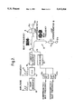
- FIG. 1 is a schematic diagram illustrating the principle underlying the invention
- FIG. 2 is a schematic diagram of a simple branched optical fibre network in which the invention may be utilised.
- FIG. 3 is a graph illustrating how the optical loss in the branches of the network of FIG. 2 can be monitored.
- FIG. 1 illustrates the principle underlying the branch identification method of the invention.
- This principle of branch identification is based upon the delay line effect of a Mach-Zehnder interferometer on a linearly-ramped FMCW 2.
- the interferometer 1 is constituted by a pair of optical fibres 1a and 1b of different lengths. The fibres 1a and 1b consequently have different optical path lengths, so that the interferometer 1 is unbalanced.
- the FMCW 2 is fed to the interferometer 1 via an input optical fibre 3 and a 2 ⁇ 2 coupler 4.
- the coupler 4 has two pairs of communication ports, a first port of one pair being connected to the fibre 3, and the second port of that pair being connected to an output optical fibre 5.
- the ports of the other pair of communication ports are connected to the optical fibres 1a and 1b.
- the other ends of the fibres 1a and 1b are connected to the ports of a first pair of communication ports of 2 ⁇ 2 coupler 6.
- the ports of the other pair of communication ports of the coupler 6 are connected to the opposite ends of an optical fibre which constitutes a loop reflector 7.
- a linearly-ramped FMCW signal produces a beat frequency when passed through an unbalanced Mach-Zehnder interferometer.
- a beat frequency is produced at the end of the interferometer 1 remote from the input fibre 3, this beat frequency being reflected back through the interferometer by the loop reflector 7, and appearing (at 8) on the output fibre 5.
- the frequency of this beat is dependent upon the imbalance in the arms of the interferometer, and takes the form of an amplitude modulated carrier wave.
- the beat frequency also appears on the fibre 3 as the inverse of the beat frequency 8 on the output fibre 5.
- This principle can be exploited in order to obtain a unique signal from each branch of a branched optical network, for example by installing differently unbalanced interferometers into the different branches.
- a suitable, linearly-ramped FMCW modulated laser signal is launched into the network, and the returned beat frequencies are filtered and monitored, a unique signal for each branch can be identified.
- a simple branched optical network of this type is shown in FIG. 2, the network having two branches A and B, each having a Mach-Zehnder interferometer 11a and 11b respectively and a loop reflector 12a and 12b respectively.
- the interferometers 11a and 11b have different imbalances.
- a ramp generator 13 is used to produce a linearly-ramped variable voltage signal which is fed to a voltage controlled oscillator (VCO) 14, the frequency of the output signal of which is proportional to the amplitude (voltage) of its input signal.
- VCO voltage controlled oscillator
- the output of the VCO is, therefore, a FMCW signal (indicated by the reference numeral 15).
- THE FMCW signal 15 is used to drive a laser 16 which launches a linearly-ramped FMCW optical signal into an optical fibre 17.
- the fibre 17 is connected to the two branches A and B by a 2 ⁇ 2 coupler 18.
- the coupler 18 has two pairs of communication ports, a first port of one pair being connected to the fibre 17, the other port of this pair being connected to an output fibre 19.
- the two ports of the other pair of communication ports of the coupler 18 are connected to the optical fibres of the branch lines A and B.
- the output fibre 19 leads to an optical receiver 20 which converts received optical signals into corresponding electrical signals.
- the output of the receiver 20 (a combination of the electrical frequencies corresponding to the optical beat frequencies generated in the Mach-Zehnder interferometers 11a and 11b and returned along the branches A and B by the loop reflectors 12a and 12b) is fed to a pair of standard analogue band pass filters 21a and 21b. These filters 21a and 21b are typically higher order Butterworth band pass filters.
- the pass bands of the filters 21a and 21b are chosen so as to filter out a respective one of the beat frequencies, and these are dependent upon the FMCW signal, the imbalance of the associated interferometers, and the range of the frequency ramp of the FMCW signal.
- an optical network having a much larger number of branches could be monitored for optical losses using the delay line effect of Mach-Zehnder interferometers on a linearly-ramped FMCW.
- the system could be used to monitor an infinite number of branches, but in practice the number of branches is limited by the number of beat frequencies that can be filtered from the returned signal. This number can be maximised by minimising interference (cross-talk) between the different beat frequencies by making the beat frequencies non-integer multiples of one another.
- the interferometers could be made transparent to traffic signals by using task-specific wavelength division multiplexers (WDMs) instead of the couplers 4 and 6 and an OTDR wavelength different from the traffic wavelength.
- WDMs task-specific wavelength division multiplexers
- the traffic signals could by-pass the interferometers, in which case the interferometers could be provided with filters for removing the traffic signals.
- interferometers are shown at the ends of the branches A and B, it would, of course, be possible to incorporate each of the interferometers anywhere in a branch. It would also be possible to provide more than one interferometer in a branch line, thereby facilitating more specific loss location in long branches.
- the main advantage of the branch identification system described above is that the change in optical loss in any one of a large number of individual branches of a branched optical network can be determined using only one optical wavelength, thus freeing the remaining spectrum for user traffic.
- the system is also cheap, as a cheap optical receiver can be used, and the interferometers are also very cheap (being basically two simple optical couplers and two lengths of optical fibre).
Abstract
Description
Claims (20)
Applications Claiming Priority (3)
| Application Number | Priority Date | Filing Date | Title |
|---|---|---|---|
| GB9007974 | 1990-04-09 | ||
| GB909007974A GB9007974D0 (en) | 1990-04-09 | 1990-04-09 | Loss detection |
| PCT/GB1991/000540 WO1991015744A1 (en) | 1990-04-09 | 1991-04-08 | Optical fibre loss detection |
Publications (1)
| Publication Number | Publication Date |
|---|---|
| US5412464A true US5412464A (en) | 1995-05-02 |
Family
ID=10674126
Family Applications (1)
| Application Number | Title | Priority Date | Filing Date |
|---|---|---|---|
| US07/949,846 Expired - Lifetime US5412464A (en) | 1990-04-09 | 1991-04-08 | Apparatus and method for monitoring losses in a branched optical fibre network |
Country Status (10)
| Country | Link |
|---|---|
| US (1) | US5412464A (en) |
| EP (1) | EP0524252B1 (en) |
| JP (1) | JP3126379B2 (en) |
| AU (1) | AU640227B2 (en) |
| CA (1) | CA2080117C (en) |
| DE (1) | DE69108232T2 (en) |
| ES (1) | ES2069885T3 (en) |
| GB (1) | GB9007974D0 (en) |
| HK (1) | HK139496A (en) |
| WO (1) | WO1991015744A1 (en) |
Cited By (29)
| Publication number | Priority date | Publication date | Assignee | Title |
|---|---|---|---|---|
| US5801830A (en) * | 1996-02-14 | 1998-09-01 | Wavelinq, Inc. | Apparatus and associated methods of detecting optical carriers and measuring characteristics thereof |
| US5808761A (en) * | 1993-07-15 | 1998-09-15 | Gec-Marconi Limited | Path integrity proving in optical communications systems |
| US20040156093A1 (en) * | 1996-12-23 | 2004-08-12 | Kristiansen Rene E. | Bidirectional router and a method of bidirectional amplification |
| WO2006064243A1 (en) * | 2004-12-17 | 2006-06-22 | British Telecommunications Public Limited Company | Assessing a network |
| US20060256344A1 (en) * | 2003-09-30 | 2006-11-16 | British Telecommunications Public Limited Company | Optical sensing |
| US20070036542A1 (en) * | 2005-07-28 | 2007-02-15 | Alcatel | Method for recognizing the integrity of an optical access line, optical system, tree-shaped access network, measuring unit, reflector and optical transmit and receive unit |
| US20070065150A1 (en) * | 2003-09-30 | 2007-03-22 | British Telecommunications Public Limited Company | Secure optical communication |
| US20070264012A1 (en) * | 2004-09-30 | 2007-11-15 | Peter Healey | Identifying or Locating Waveguides |
| US20080018908A1 (en) * | 2004-12-17 | 2008-01-24 | Peter Healey | Optical System |
| US20080166120A1 (en) * | 2005-03-04 | 2008-07-10 | David Heatley | Acoustic Modulation |
| US20080219093A1 (en) * | 2005-03-04 | 2008-09-11 | Emc Corporation | Sensing System |
| US20080232242A1 (en) * | 2004-03-31 | 2008-09-25 | Peter Healey | Evaluating the Position of a Disturbance |
| US20080278711A1 (en) * | 2004-09-30 | 2008-11-13 | British Telecommunications Public Limited Company | Distributed Backscattering |
| US20090014634A1 (en) * | 2005-06-02 | 2009-01-15 | British Telecommunications Public Limited Company | Evaluating the position of a disturbance |
| US20090054809A1 (en) * | 2005-04-08 | 2009-02-26 | Takeharu Morishita | Sampling Device for Viscous Sample, Homogenization Method for Sputum and Method of Detecting Microbe |
| US20090097844A1 (en) * | 2006-02-24 | 2009-04-16 | Peter Healey | Sensing a disturbance |
| US20090103928A1 (en) * | 2005-04-14 | 2009-04-23 | Peter Healey | Communicating or reproducing an audible sound |
| US20090135428A1 (en) * | 2006-02-24 | 2009-05-28 | Peter Healey | Sensing a disturbance |
| US20090252491A1 (en) * | 2006-02-24 | 2009-10-08 | Peter Healey | Sensing a disturbance |
| US20090274456A1 (en) * | 2006-04-03 | 2009-11-05 | Peter Healey | Evaluating the position of a disturbance |
| US20090275002A1 (en) * | 2008-04-30 | 2009-11-05 | Lindsey Hoggle | Nutrition informatics method |
| US20100135653A1 (en) * | 2008-12-03 | 2010-06-03 | National Taiwan University Of Science And Technology | Optical network monitoring system and method thereof |
| CN101080884B (en) * | 2004-12-17 | 2013-02-27 | 英国电讯有限公司 | Assessing a network |
| US8396360B2 (en) | 2005-03-31 | 2013-03-12 | British Telecommunications Public Limited Company | Communicating information |
| US20170293083A1 (en) * | 2016-04-11 | 2017-10-12 | Michael Menard | Optical loop enhanced optical modulators |
| WO2019011432A1 (en) * | 2017-07-12 | 2019-01-17 | Telefonaktiebolaget Lm Ericsson (Publ) | Methods and apparatus for detecting a fault in an optical communication network |
| US10365088B2 (en) * | 2016-03-29 | 2019-07-30 | Tianjin University | Distributed measuring device and method for simultaneously measuring strain and temperature based on optical frequency domain reflection |
| US10536236B2 (en) | 2013-08-26 | 2020-01-14 | Coriant Operations, Inc. | Intranodal ROADM fiber management apparatuses, systems, and methods |
| CN112219099A (en) * | 2018-06-04 | 2021-01-12 | 住友电工光学前沿株式会社 | Inspection system |
Families Citing this family (2)
| Publication number | Priority date | Publication date | Assignee | Title |
|---|---|---|---|---|
| GB9202564D0 (en) * | 1992-02-07 | 1992-03-25 | Marconi Gec Ltd | Optical signal transmission network |
| US9178611B2 (en) * | 2011-06-28 | 2015-11-03 | Intuitive Surgical Operations, Inc. | Fiber optic network interrogation tool for combined swept-heterodyne optical spectrum analysis and optical frequency-domain reflectometry |
Citations (5)
| Publication number | Priority date | Publication date | Assignee | Title |
|---|---|---|---|---|
| US3551682A (en) * | 1968-04-26 | 1970-12-29 | Compteurs Comp D | Device for measuring relative displacement between plural light sources and a scale utilizing frequency multiplexing |
| GB2181921A (en) * | 1985-10-15 | 1987-04-29 | Plessey Co Plc | Optical communications system |
| US4875772A (en) * | 1988-10-04 | 1989-10-24 | Laser Precision Corporation | Remotely controlled optical time domain reflectometer serving a plurality of fiber optic cables |
| JPH01280235A (en) * | 1988-05-06 | 1989-11-10 | Nippon Telegr & Teleph Corp <Ntt> | Evaluating device for characteristic of branch light beam path |
| WO1990006498A2 (en) * | 1988-12-06 | 1990-06-14 | British Telecommunications Public Limited Company | Loss detection |
-
1990
- 1990-04-09 GB GB909007974A patent/GB9007974D0/en active Pending
-
1991
- 1991-04-08 EP EP91908130A patent/EP0524252B1/en not_active Expired - Lifetime
- 1991-04-08 WO PCT/GB1991/000540 patent/WO1991015744A1/en active IP Right Grant
- 1991-04-08 ES ES91908130T patent/ES2069885T3/en not_active Expired - Lifetime
- 1991-04-08 AU AU76757/91A patent/AU640227B2/en not_active Ceased
- 1991-04-08 CA CA002080117A patent/CA2080117C/en not_active Expired - Fee Related
- 1991-04-08 JP JP03507494A patent/JP3126379B2/en not_active Expired - Fee Related
- 1991-04-08 DE DE69108232T patent/DE69108232T2/en not_active Expired - Lifetime
- 1991-04-08 US US07/949,846 patent/US5412464A/en not_active Expired - Lifetime
-
1996
- 1996-07-25 HK HK139496A patent/HK139496A/en not_active IP Right Cessation
Patent Citations (5)
| Publication number | Priority date | Publication date | Assignee | Title |
|---|---|---|---|---|
| US3551682A (en) * | 1968-04-26 | 1970-12-29 | Compteurs Comp D | Device for measuring relative displacement between plural light sources and a scale utilizing frequency multiplexing |
| GB2181921A (en) * | 1985-10-15 | 1987-04-29 | Plessey Co Plc | Optical communications system |
| JPH01280235A (en) * | 1988-05-06 | 1989-11-10 | Nippon Telegr & Teleph Corp <Ntt> | Evaluating device for characteristic of branch light beam path |
| US4875772A (en) * | 1988-10-04 | 1989-10-24 | Laser Precision Corporation | Remotely controlled optical time domain reflectometer serving a plurality of fiber optic cables |
| WO1990006498A2 (en) * | 1988-12-06 | 1990-06-14 | British Telecommunications Public Limited Company | Loss detection |
Non-Patent Citations (8)
| Title |
|---|
| Applied Optics, vol. 26, No. 9, 1 May 1987, Optical Society of America, Takada et al: "New Measurement System for Fault Location in Optical Waveguide Devices Based on An Interferometric Technique," pp. 1603-1606. |
| Applied Optics, vol. 26, No. 9, 1 May 1987, Optical Society of America, Takada et al: New Measurement System for Fault Location in Optical Waveguide Devices Based on An Interferometric Technique, pp. 1603 1606. * |
| Electronics Letters, vol. 25, No. 2, 19 Jan. 1989; Dolfi et al: "Optical Frequency Domain Reflectometry With High Sensitivity And Resolution Using Optical Synchronous Detection With Coded Modulators," pp. 160-162. |
| Electronics Letters, vol. 25, No. 2, 19 Jan. 1989; Dolfi et al: Optical Frequency Domain Reflectometry With High Sensitivity And Resolution Using Optical Synchronous Detection With Coded Modulators, pp. 160 162. * |
| Journal of Physics D. Applied Physics, vol. 19., No. 12, Dec. 1986, The Institute of Physics, Rogers: "Distributed Optical-Fibre Sensors," pp. 2237-2255. |
| Journal of Physics D. Applied Physics, vol. 19., No. 12, Dec. 1986, The Institute of Physics, Rogers: Distributed Optical Fibre Sensors, pp. 2237 2255. * |
| Patent Abstracts of Japan, vol. 14, No. 50 (P 998) (3993), 30 Jan. 1990, & JP A 1280235 (Nippon Telegr. & Teleph. Corp.) 10 Nov. 1989. * |
| Patent Abstracts of Japan, vol. 14, No. 50 (P-998) (3993), 30 Jan. 1990, & JP A 1280235 (Nippon Telegr. & Teleph. Corp.) 10 Nov. 1989. |
Cited By (48)
| Publication number | Priority date | Publication date | Assignee | Title |
|---|---|---|---|---|
| US5808761A (en) * | 1993-07-15 | 1998-09-15 | Gec-Marconi Limited | Path integrity proving in optical communications systems |
| US5801830A (en) * | 1996-02-14 | 1998-09-01 | Wavelinq, Inc. | Apparatus and associated methods of detecting optical carriers and measuring characteristics thereof |
| US20040156093A1 (en) * | 1996-12-23 | 2004-08-12 | Kristiansen Rene E. | Bidirectional router and a method of bidirectional amplification |
| US7277635B2 (en) * | 1996-12-23 | 2007-10-02 | Tellabs Denmark A/S | Bidirectional router and a method of bidirectional amplification |
| US20080031622A1 (en) * | 1996-12-23 | 2008-02-07 | Tellabs Denmark A/S | Bidirectional Router and a Method of Bidirectional Amplification |
| US7667849B2 (en) | 2003-09-30 | 2010-02-23 | British Telecommunications Public Limited Company | Optical sensor with interferometer for sensing external physical disturbance of optical communications link |
| US20060256344A1 (en) * | 2003-09-30 | 2006-11-16 | British Telecommunications Public Limited Company | Optical sensing |
| US7796896B2 (en) | 2003-09-30 | 2010-09-14 | British Telecommunications Plc | Secure optical communication |
| US20070065150A1 (en) * | 2003-09-30 | 2007-03-22 | British Telecommunications Public Limited Company | Secure optical communication |
| US7974182B2 (en) | 2004-03-31 | 2011-07-05 | British Telecommunications Public Limited Company | Evaluating the position of a disturbance |
| US20080232242A1 (en) * | 2004-03-31 | 2008-09-25 | Peter Healey | Evaluating the Position of a Disturbance |
| US20080278711A1 (en) * | 2004-09-30 | 2008-11-13 | British Telecommunications Public Limited Company | Distributed Backscattering |
| US7995197B2 (en) | 2004-09-30 | 2011-08-09 | British Telecommunications Public Limited Company | Distributed backscattering |
| US20070264012A1 (en) * | 2004-09-30 | 2007-11-15 | Peter Healey | Identifying or Locating Waveguides |
| US7848645B2 (en) | 2004-09-30 | 2010-12-07 | British Telecommunications Public Limited Company | Identifying or locating waveguides |
| US20080123085A1 (en) * | 2004-12-17 | 2008-05-29 | Sikora Edmund Sr | Assessing A Network |
| US8045174B2 (en) * | 2004-12-17 | 2011-10-25 | British Telecommunications Public Limited Company | Assessing a network |
| US20080018908A1 (en) * | 2004-12-17 | 2008-01-24 | Peter Healey | Optical System |
| US7656535B2 (en) | 2004-12-17 | 2010-02-02 | British Telecommunications Public Limited Company | Optical system and method for inferring a disturbance |
| CN101080884B (en) * | 2004-12-17 | 2013-02-27 | 英国电讯有限公司 | Assessing a network |
| WO2006064243A1 (en) * | 2004-12-17 | 2006-06-22 | British Telecommunications Public Limited Company | Assessing a network |
| US20080166120A1 (en) * | 2005-03-04 | 2008-07-10 | David Heatley | Acoustic Modulation |
| US7697795B2 (en) | 2005-03-04 | 2010-04-13 | British Telecommunications Public Limited Company | Acoustic modulation |
| US20080219093A1 (en) * | 2005-03-04 | 2008-09-11 | Emc Corporation | Sensing System |
| US7755971B2 (en) | 2005-03-04 | 2010-07-13 | British Telecommunications Public Limited Company | Sensing system |
| US8396360B2 (en) | 2005-03-31 | 2013-03-12 | British Telecommunications Public Limited Company | Communicating information |
| US20090054809A1 (en) * | 2005-04-08 | 2009-02-26 | Takeharu Morishita | Sampling Device for Viscous Sample, Homogenization Method for Sputum and Method of Detecting Microbe |
| US20090103928A1 (en) * | 2005-04-14 | 2009-04-23 | Peter Healey | Communicating or reproducing an audible sound |
| US8000609B2 (en) | 2005-04-14 | 2011-08-16 | British Telecommunications Public Limited Company | Communicating or reproducing an audible sound |
| US8003932B2 (en) | 2005-06-02 | 2011-08-23 | British Telecommunications Public Limited Company | Evaluating the position of a disturbance |
| US20090014634A1 (en) * | 2005-06-02 | 2009-01-15 | British Telecommunications Public Limited Company | Evaluating the position of a disturbance |
| US20070036542A1 (en) * | 2005-07-28 | 2007-02-15 | Alcatel | Method for recognizing the integrity of an optical access line, optical system, tree-shaped access network, measuring unit, reflector and optical transmit and receive unit |
| US20090097844A1 (en) * | 2006-02-24 | 2009-04-16 | Peter Healey | Sensing a disturbance |
| US20090135428A1 (en) * | 2006-02-24 | 2009-05-28 | Peter Healey | Sensing a disturbance |
| US7817279B2 (en) | 2006-02-24 | 2010-10-19 | British Telecommunications Public Limited Company | Sensing a disturbance |
| US20090252491A1 (en) * | 2006-02-24 | 2009-10-08 | Peter Healey | Sensing a disturbance |
| US8027584B2 (en) | 2006-02-24 | 2011-09-27 | British Telecommunications Public Limited Company | Sensing a disturbance |
| US7961331B2 (en) | 2006-02-24 | 2011-06-14 | British Telecommunications Public Limited Company | Sensing a disturbance along an optical path |
| US8670662B2 (en) | 2006-04-03 | 2014-03-11 | British Telecommunications Public Limited Company | Evaluating the position of an optical fiber disturbance |
| US20090274456A1 (en) * | 2006-04-03 | 2009-11-05 | Peter Healey | Evaluating the position of a disturbance |
| US20090275002A1 (en) * | 2008-04-30 | 2009-11-05 | Lindsey Hoggle | Nutrition informatics method |
| US20100135653A1 (en) * | 2008-12-03 | 2010-06-03 | National Taiwan University Of Science And Technology | Optical network monitoring system and method thereof |
| US10536236B2 (en) | 2013-08-26 | 2020-01-14 | Coriant Operations, Inc. | Intranodal ROADM fiber management apparatuses, systems, and methods |
| US10365088B2 (en) * | 2016-03-29 | 2019-07-30 | Tianjin University | Distributed measuring device and method for simultaneously measuring strain and temperature based on optical frequency domain reflection |
| US20170293083A1 (en) * | 2016-04-11 | 2017-10-12 | Michael Menard | Optical loop enhanced optical modulators |
| WO2019011432A1 (en) * | 2017-07-12 | 2019-01-17 | Telefonaktiebolaget Lm Ericsson (Publ) | Methods and apparatus for detecting a fault in an optical communication network |
| CN112219099A (en) * | 2018-06-04 | 2021-01-12 | 住友电工光学前沿株式会社 | Inspection system |
| US11965801B2 (en) | 2018-06-04 | 2024-04-23 | Sumitomo Electric Optifrontier Co., Ltd. | Measurement system |
Also Published As
| Publication number | Publication date |
|---|---|
| HK139496A (en) | 1996-08-02 |
| CA2080117A1 (en) | 1991-10-10 |
| ES2069885T3 (en) | 1995-05-16 |
| AU640227B2 (en) | 1993-08-19 |
| GB9007974D0 (en) | 1990-06-06 |
| JP3126379B2 (en) | 2001-01-22 |
| DE69108232D1 (en) | 1995-04-20 |
| EP0524252B1 (en) | 1995-03-15 |
| DE69108232T2 (en) | 1995-07-20 |
| JPH05506099A (en) | 1993-09-02 |
| CA2080117C (en) | 1999-02-02 |
| WO1991015744A1 (en) | 1991-10-17 |
| EP0524252A1 (en) | 1993-01-27 |
| AU7675791A (en) | 1991-10-30 |
Similar Documents
| Publication | Publication Date | Title |
|---|---|---|
| US5412464A (en) | Apparatus and method for monitoring losses in a branched optical fibre network | |
| KR101174223B1 (en) | Optical fiber circuit monitoring system and monitoring device included in this system | |
| US6269204B1 (en) | Method and system for monitoring of optical transmission lines | |
| EP1825613B1 (en) | Assessing a network | |
| US8654320B2 (en) | Beam Path Monitoring Device and Beam Path Monitoring System | |
| JP5521118B2 (en) | Optical line characteristic analyzer and analysis method thereof | |
| US20080291461A1 (en) | Method and apparatus for suppression of crosstalk and noise in time-division multiplexed interferometric sensor systems | |
| NO339298B1 (en) | Active coherence reduction for interferometer interrogation | |
| JPH11160200A (en) | Distribution type sensor device nd distribution type sensing method | |
| CA2906964A1 (en) | Brillouin optical distributed sensing device and method with improved tolerance to sensor failure | |
| Tsuji et al. | Coherent optical frequency domain reflectometry for a long single-mode optical fiber using a coherent lightwave source and an external phase modulator | |
| US4777661A (en) | Apparatus and method for self-referencing and multiplexing intensity modulating fiber optic sensors | |
| WO2019148061A1 (en) | High speed frequency hopping das interrogation using aom-gated re-circulating loop and frequency-shifted receiver lo | |
| CN111397851A (en) | OFDR multi-path optical fiber sensing system and method based on optical frequency comb technology | |
| CN110492927A (en) | It is a kind of that relaying submarine optical fiber cable disturbance monitoring system is had based on bank base detection | |
| JP2575794B2 (en) | Optical fiber characteristics evaluation device | |
| JPH07503821A (en) | Optical signal transmission network | |
| Kist | FIBER-OPTIC SENSORS FOR NETWORK | |
| AU1857201A (en) | Process and apparatus for measuring polarisation dispersion in optical fibres | |
| JP5907907B2 (en) | Optical line characteristic analyzer and analysis method thereof | |
| EP3100005A1 (en) | Optical distributed sensing device and method for measurements over extended ranges | |
| Iiyama et al. | Frequency domain detection of coherence multiplexed sensor signals by using an optical loop with a frequency shifter | |
| EP0397636B1 (en) | Device and procedure for measuring with optical fibre sensors, and sensor utilised therewith | |
| RU1826134C (en) | Optical cable attenuation measuring device | |
| JP2002022600A (en) | Optical cable testing apparatus and method |
Legal Events
| Date | Code | Title | Description |
|---|---|---|---|
| AS | Assignment |
Owner name: BRITISH TELECOMMUNICATIONS PUBLIC LIMITED COMPANY Free format text: ASSIGNMENT OF ASSIGNORS INTEREST;ASSIGNORS:THOMAS, GLENN ANDREW;JAMES, SIMON MARK;ROWE, CHRISTOPHER JOHN;REEL/FRAME:006632/0930 Effective date: 19921105 |
|
| STCF | Information on status: patent grant |
Free format text: PATENTED CASE |
|
| FPAY | Fee payment |
Year of fee payment: 4 |
|
| FEPP | Fee payment procedure |
Free format text: PAYOR NUMBER ASSIGNED (ORIGINAL EVENT CODE: ASPN); ENTITY STATUS OF PATENT OWNER: LARGE ENTITY |
|
| FPAY | Fee payment |
Year of fee payment: 8 |
|
| FPAY | Fee payment |
Year of fee payment: 12 |