US5380195A - Portable safety flare for combustion of waste gases - Google Patents
Portable safety flare for combustion of waste gases Download PDFInfo
- Publication number
- US5380195A US5380195A US08/164,550 US16455093A US5380195A US 5380195 A US5380195 A US 5380195A US 16455093 A US16455093 A US 16455093A US 5380195 A US5380195 A US 5380195A
- Authority
- US
- United States
- Prior art keywords
- container
- vent stack
- burner
- interior
- flare
- Prior art date
- Legal status (The legal status is an assumption and is not a legal conclusion. Google has not performed a legal analysis and makes no representation as to the accuracy of the status listed.)
- Expired - Fee Related
Links
Images
Classifications
-
- F—MECHANICAL ENGINEERING; LIGHTING; HEATING; WEAPONS; BLASTING
- F23—COMBUSTION APPARATUS; COMBUSTION PROCESSES
- F23G—CREMATION FURNACES; CONSUMING WASTE PRODUCTS BY COMBUSTION
- F23G7/00—Incinerators or other apparatus for consuming industrial waste, e.g. chemicals
- F23G7/06—Incinerators or other apparatus for consuming industrial waste, e.g. chemicals of waste gases or noxious gases, e.g. exhaust gases
- F23G7/08—Incinerators or other apparatus for consuming industrial waste, e.g. chemicals of waste gases or noxious gases, e.g. exhaust gases using flares, e.g. in stacks
- F23G7/085—Incinerators or other apparatus for consuming industrial waste, e.g. chemicals of waste gases or noxious gases, e.g. exhaust gases using flares, e.g. in stacks in stacks
Definitions
- the present invention relates to a portable safety flare for the combustion of waste gases
- flares for the safe disposal through combustion of waste gases are well known. It has been discovered, however, that environmental problems are associated with the use of flares when liquids are mixed in with the waste gases.
- the safety flare is configured in the form of a flare stack, fine droplets of liquid are sprayed over vegetation in the surrounding countryside.
- the safety flare is configured in the form of a flare pit, a contaminated residue is left in the ground from the liquid.
- a safety flare for combustion of waste gases which includes a container having an interior and an exterior.
- the interior is defined by a bottom and peripheral sidewalls.
- a vent stack extends through the interior of the container.
- the vent stack has a first end and a second end. The first end communicates with the exterior of the container adjacent the bottom. The second end extends past a top peripheral edge of the peripheral sidewalls of the container. Means is provided for permitting the communication of combustion air with the first end of the vent stack.
- a burner is positioned immediately surrounding the second end of the vent stack such that the burner is supplied with combustion air by the vent stack.
- the burner has a plurality of downwardly directed nozzles such that liquids passing through the nozzles fall by force of gravity into the interior of the container.
- liquid containment is, of course, enhanced when the container is a closed one. Even more beneficial results may, therefore, be obtained when a shroud extends from the top peripheral edge of the container to the burner.
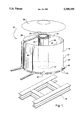
- FIG. 1 is an exploded perspective view of a safety flare constructed in accordance with the teachings of the present invention.
- Safety flare 10 includes a container 12 having an interior 14 and an exterior 16. Interior 14 is defined by a bottom 18 and peripheral sidewalls 20.
- a vent stack 22 extends through interior 14 of container 12.
- Vent stack 22 has a first end 24 and a second end 26. First end 24 communicates with exterior 16 of container 12 adjacent bottom 18. Second end 26 extends past a top peripheral edge 28 of peripheral sidewalls 20 of container 12.
- a plurality of vents 30 positioned adjacent bottom 18 serve as means for permitting the communication of combustion air with first end 24 of vent stack 22.
- a ring-form burner 32 is positioned immediately surrounding second end 26 of vent stack 22, such that burner 32 is supplied with combustion air by vent stack 22. Burner 32 has a plurality of downwardly directed nozzles 34 such that liquids passing through nozzles 34 fall by force of gravity into interior 14 of container 12.
- a shroud 36 extends from top peripheral edge 28 of container 12 to burner 32. Shroud 36 enhances liquid containment.
- Container 12 is mounted on a skid assembly 38. Skid assembly 38 makes container 12 easy to move onto remote sites.
- Container 12 has a drain passageway 40 through peripheral sidewalls 20 adjacent bottom 18. Liquids are periodically drained via drain passageway 40.
- An overflow outlet pipe 42 is provided adjacent top peripheral edge 28 of container 12. Overflow outlet pipe 42 is intended to provide relief in the event the accumulation of liquids exceeds the capacity of container 12. Overflow outlet pipe 42 is intended for connection to supplemental storage (not shown).
- Burner 32 is connected to a source of waste gas (not shown).
- the waste gas flows to nozzles 34 where it is ignited.
- Nozzles 34 are directed downwardly to permit any liquids carried to burner 32 by the waste gas to fall by force of gravity into interior 14 of container 12.
- Combustion air is provided to burner 32 by vent stack 22.
- container 12 Periodically, container 12 is drained of accumulated liquids via drain passageway 40.
Landscapes
- Engineering & Computer Science (AREA)
- Environmental & Geological Engineering (AREA)
- Mechanical Engineering (AREA)
- General Engineering & Computer Science (AREA)
- Incineration Of Waste (AREA)
Abstract
A safety flare for combustion of waste gases is described which includes a container having an interior and an exterior. The interior is defined by a bottom and peripheral sidewalls. A vent stack extends through the interior of the container. The vent stack has a first end and a second end. The first end communicates with the exterior of the container adjacent the bottom. The second end extends past a top peripheral edge of the peripheral sidewalls of the container. Means is provided for permitting the communication of combustion air with the first end of the vent stack. A burner is positioned immediately surrounding the second end of the vent stack such that the burner is supplied with combustion air by the vent stack. The burner has a plurality of downwardly directed nozzles such that liquids passing through the nozzles fall by force of gravity into the interior of the container. This safety flare is intended to replace flare stacks and flare pits formerly used in the oil and gas industry.
Description
The present invention relates to a portable safety flare for the combustion of waste gases
The use of flares for the safe disposal through combustion of waste gases is well known. It has been discovered, however, that environmental problems are associated with the use of flares when liquids are mixed in with the waste gases. When the safety flare is configured in the form of a flare stack, fine droplets of liquid are sprayed over vegetation in the surrounding countryside. When the safety flare is configured in the form of a flare pit, a contaminated residue is left in the ground from the liquid.
What is required is a safety flare for the combustion of waste gases that includes means for containing liquids.
According to the present invention there is provided a safety flare for combustion of waste gases which includes a container having an interior and an exterior. The interior is defined by a bottom and peripheral sidewalls. A vent stack extends through the interior of the container. The vent stack has a first end and a second end. The first end communicates with the exterior of the container adjacent the bottom. The second end extends past a top peripheral edge of the peripheral sidewalls of the container. Means is provided for permitting the communication of combustion air with the first end of the vent stack. A burner is positioned immediately surrounding the second end of the vent stack such that the burner is supplied with combustion air by the vent stack. The burner has a plurality of downwardly directed nozzles such that liquids passing through the nozzles fall by force of gravity into the interior of the container.
A lot of research went into the development of the safety flare as described. Initially, a container was constructed with a burner disposed about the peripheral sidewalls. The nozzles of the burner were directed downwardly to promote liquids falling by force of gravity into the container. It was discovered, however, that the burner gave off an intense heat which resulted in a deterioration of the condition of the container. The burner was then moved away from the sidewalls of the container, but problems were encountered with ensuring that the burner was supplied with sufficient combustion air to have a "clean" burn. A black sooty build up in the container was the result, especially when an annular shroud was placed upon the container to enhance liquid containment. The addition of a vent stack, with the burner configured around the vent stack resulted in an efficiently operating safety flare to which other features could then be added to enhance its operation.
Although beneficial results may be obtained through the use of the safety flare, as described above, liquid containment is, of course, enhanced when the container is a closed one. Even more beneficial results may, therefore, be obtained when a shroud extends from the top peripheral edge of the container to the burner.
These and other features of the invention will become more apparent from the following description in which reference is made to the appended drawings, wherein:
FIG. 1 is an exploded perspective view of a safety flare constructed in accordance with the teachings of the present invention.
The preferred embodiment, a safety flare for combustion of waste gases generally identified by reference numeral 10, will now be described with reference to FIG. 1.
In order to enhance operation safety flare 10 includes a number of additional features. A shroud 36 extends from top peripheral edge 28 of container 12 to burner 32. Shroud 36 enhances liquid containment. Container 12 is mounted on a skid assembly 38. Skid assembly 38 makes container 12 easy to move onto remote sites. Container 12 has a drain passageway 40 through peripheral sidewalls 20 adjacent bottom 18. Liquids are periodically drained via drain passageway 40. An overflow outlet pipe 42 is provided adjacent top peripheral edge 28 of container 12. Overflow outlet pipe 42 is intended to provide relief in the event the accumulation of liquids exceeds the capacity of container 12. Overflow outlet pipe 42 is intended for connection to supplemental storage (not shown).
The use and operation of safety flare 10 will now be described with reference to FIG. 1. Burner 32 is connected to a source of waste gas (not shown). The waste gas flows to nozzles 34 where it is ignited. Nozzles 34 are directed downwardly to permit any liquids carried to burner 32 by the waste gas to fall by force of gravity into interior 14 of container 12. Combustion air is provided to burner 32 by vent stack 22. Periodically, container 12 is drained of accumulated liquids via drain passageway 40.
It will be apparent to one skilled in the art that modifications may be made to the illustrated embodiment without departing from the spirit and scope of the invention as defined by the Claims. In particular, the shape of container 12, vent stack 22 and burner 32 may be modified.
Claims (6)
1. A safety flare for combustion of waste gases, comprising:
a. a container having an interior and an exterior, the interior being defined by a bottom and peripheral sidewalls;
b. a vent stack extending through the interior of the container, the vent stack having a first end communicating with the exterior of the container and a second end extending past a top peripheral edge of the peripheral sidewalls of the container;
c. means for permitting the communication of combustion air with the first end of the vent stack; and
d. a burner immediately surrounding the second end of the vent stack such that the burner is supplied with combustion air by the vent stack, the burner having a plurality of downwardly directed nozzles such that liquids passing through the nozzles fall by force of gravity into the interior of the container.
2. The safety flare as defined in claim 1, wherein a shroud extends from the top peripheral edge of the container to the burner.
3. The safety flare as defined in claim 1, wherein the container is mounted on a skid assembly.
4. The safety flare as defined in claim 1, wherein the container has a drain passageway through the peripheral sidewalls adjacent the bottom.
5. The safety flare as defined in claim 1, wherein the first end of the vent stack is positioned adjacent the bottom of the container and the container has a plurality of vents adjacent the bottom as means to permit the communication of combustion air with the first end of the vent stack.
6. The safety flare as defined in claim 1, wherein an overflow outlet pipe is provided adjacent the top peripheral edge of the container.
Priority Applications (2)
| Application Number | Priority Date | Filing Date | Title |
|---|---|---|---|
| US08/164,550 US5380195A (en) | 1993-12-10 | 1993-12-10 | Portable safety flare for combustion of waste gases |
| CA002113764A CA2113764A1 (en) | 1993-12-10 | 1994-01-19 | Portable safety flare for combustion of waste gases |
Applications Claiming Priority (1)
| Application Number | Priority Date | Filing Date | Title |
|---|---|---|---|
| US08/164,550 US5380195A (en) | 1993-12-10 | 1993-12-10 | Portable safety flare for combustion of waste gases |
Publications (1)
| Publication Number | Publication Date |
|---|---|
| US5380195A true US5380195A (en) | 1995-01-10 |
Family
ID=22595012
Family Applications (1)
| Application Number | Title | Priority Date | Filing Date |
|---|---|---|---|
| US08/164,550 Expired - Fee Related US5380195A (en) | 1993-12-10 | 1993-12-10 | Portable safety flare for combustion of waste gases |
Country Status (2)
| Country | Link |
|---|---|
| US (1) | US5380195A (en) |
| CA (1) | CA2113764A1 (en) |
Cited By (14)
| Publication number | Priority date | Publication date | Assignee | Title |
|---|---|---|---|---|
| US5498153A (en) * | 1994-07-25 | 1996-03-12 | Jones; Wendyle | Gas flare |
| US5788477A (en) * | 1997-03-26 | 1998-08-04 | Jones; Wendyle | Gas flare |
| US5803726A (en) * | 1996-10-04 | 1998-09-08 | Bacon; David W. | Retractable, electric arc-ignited gas pilot for igniting flare stacks |
| US5807095A (en) * | 1995-11-09 | 1998-09-15 | Altex Oilfield Equipment Ltd. | Portable flare tank |
| US5882187A (en) * | 1995-11-09 | 1999-03-16 | Modern Industrial Rentals (1978) Ltd. | Portable flare tank |
| US5919036A (en) * | 1996-12-02 | 1999-07-06 | O'brien; Alan | Method and apparatus for burning combustible gases |
| US5971744A (en) * | 1997-06-11 | 1999-10-26 | Eaton; Timothy C. | Gas burner tool for purging a gas supply pipe |
| US5997284A (en) * | 1996-11-08 | 1999-12-07 | Altex Oilfield Equipment, Ltd. | Portable flare tank for degassing of drilling fluid |
| US6431855B1 (en) | 1999-07-09 | 2002-08-13 | Porta-Stack Inc. | Portable flare stack |
| WO2002086386A1 (en) * | 2001-04-18 | 2002-10-31 | Aramco Services Company | Flare stack combustion apparatus and method |
| US20030106694A1 (en) * | 2001-12-11 | 2003-06-12 | Wiseman Thomas R. | Method for disposal of liquid from gas wells |
| US20060199126A1 (en) * | 2005-02-16 | 2006-09-07 | Alberta Welltest Incinerators Ltd. | Gas phase thermal unit |
| USD768844S1 (en) * | 2015-05-18 | 2016-10-11 | Saudi Arabian Oil Company | Catalyst basket |
| US20220113026A1 (en) * | 2020-10-08 | 2022-04-14 | Saudi Arabian Oil Company | Flare spill control system |
Citations (9)
| Publication number | Priority date | Publication date | Assignee | Title |
|---|---|---|---|---|
| US3658482A (en) * | 1970-09-08 | 1972-04-25 | College Research Corp | Afterburner |
| US4243376A (en) * | 1977-05-09 | 1981-01-06 | The British Petroleum Company Limited | Flare |
| US4255120A (en) * | 1978-12-05 | 1981-03-10 | Straitz John F Iii | Portable safety flare for combustion of waste gases |
| US4269583A (en) * | 1978-05-22 | 1981-05-26 | Combustion Unlimited Incorporated | Pilots for flare stacks |
| US4516932A (en) * | 1982-05-06 | 1985-05-14 | Cabinet Brot | Safety system intended in particular to elminate entrained or condensed liquids, and to limit the heat radiation when flaring or dispersing hydrocarbon gases |
| US4799878A (en) * | 1987-11-16 | 1989-01-24 | Schaeffer Thomas W | Rich fume incinerator |
| US4802432A (en) * | 1986-07-01 | 1989-02-07 | Single Buoy Moorings Inc. | Mooring device |
| US4975042A (en) * | 1985-11-26 | 1990-12-04 | John Zink Company | Method and burner apparatus for flaring inert vitiated waste gases |
| US5253596A (en) * | 1991-05-10 | 1993-10-19 | Bono Energia S.P.A. | Method and unit for the thermal destruction of pollutant wastes |
-
1993
- 1993-12-10 US US08/164,550 patent/US5380195A/en not_active Expired - Fee Related
-
1994
- 1994-01-19 CA CA002113764A patent/CA2113764A1/en not_active Abandoned
Patent Citations (9)
| Publication number | Priority date | Publication date | Assignee | Title |
|---|---|---|---|---|
| US3658482A (en) * | 1970-09-08 | 1972-04-25 | College Research Corp | Afterburner |
| US4243376A (en) * | 1977-05-09 | 1981-01-06 | The British Petroleum Company Limited | Flare |
| US4269583A (en) * | 1978-05-22 | 1981-05-26 | Combustion Unlimited Incorporated | Pilots for flare stacks |
| US4255120A (en) * | 1978-12-05 | 1981-03-10 | Straitz John F Iii | Portable safety flare for combustion of waste gases |
| US4516932A (en) * | 1982-05-06 | 1985-05-14 | Cabinet Brot | Safety system intended in particular to elminate entrained or condensed liquids, and to limit the heat radiation when flaring or dispersing hydrocarbon gases |
| US4975042A (en) * | 1985-11-26 | 1990-12-04 | John Zink Company | Method and burner apparatus for flaring inert vitiated waste gases |
| US4802432A (en) * | 1986-07-01 | 1989-02-07 | Single Buoy Moorings Inc. | Mooring device |
| US4799878A (en) * | 1987-11-16 | 1989-01-24 | Schaeffer Thomas W | Rich fume incinerator |
| US5253596A (en) * | 1991-05-10 | 1993-10-19 | Bono Energia S.P.A. | Method and unit for the thermal destruction of pollutant wastes |
Cited By (17)
| Publication number | Priority date | Publication date | Assignee | Title |
|---|---|---|---|---|
| US5498153A (en) * | 1994-07-25 | 1996-03-12 | Jones; Wendyle | Gas flare |
| US5807095A (en) * | 1995-11-09 | 1998-09-15 | Altex Oilfield Equipment Ltd. | Portable flare tank |
| US5882187A (en) * | 1995-11-09 | 1999-03-16 | Modern Industrial Rentals (1978) Ltd. | Portable flare tank |
| US5803726A (en) * | 1996-10-04 | 1998-09-08 | Bacon; David W. | Retractable, electric arc-ignited gas pilot for igniting flare stacks |
| US5997284A (en) * | 1996-11-08 | 1999-12-07 | Altex Oilfield Equipment, Ltd. | Portable flare tank for degassing of drilling fluid |
| US5919036A (en) * | 1996-12-02 | 1999-07-06 | O'brien; Alan | Method and apparatus for burning combustible gases |
| US5788477A (en) * | 1997-03-26 | 1998-08-04 | Jones; Wendyle | Gas flare |
| US5971744A (en) * | 1997-06-11 | 1999-10-26 | Eaton; Timothy C. | Gas burner tool for purging a gas supply pipe |
| US6431855B1 (en) | 1999-07-09 | 2002-08-13 | Porta-Stack Inc. | Portable flare stack |
| WO2002086386A1 (en) * | 2001-04-18 | 2002-10-31 | Aramco Services Company | Flare stack combustion apparatus and method |
| US20040248055A1 (en) * | 2001-04-18 | 2004-12-09 | Mashhour Mazen M. | Flare stack combustion apparatus and method |
| US7247016B2 (en) | 2001-04-18 | 2007-07-24 | Saudi Arabian Oil Company | Flare stack combustion apparatus and method |
| US20030106694A1 (en) * | 2001-12-11 | 2003-06-12 | Wiseman Thomas R. | Method for disposal of liquid from gas wells |
| US20060199126A1 (en) * | 2005-02-16 | 2006-09-07 | Alberta Welltest Incinerators Ltd. | Gas phase thermal unit |
| USD768844S1 (en) * | 2015-05-18 | 2016-10-11 | Saudi Arabian Oil Company | Catalyst basket |
| US20220113026A1 (en) * | 2020-10-08 | 2022-04-14 | Saudi Arabian Oil Company | Flare spill control system |
| US11867394B2 (en) * | 2020-10-08 | 2024-01-09 | Saudi Arabian Oil Company | Flare spill control system |
Also Published As
| Publication number | Publication date |
|---|---|
| CA2113764A1 (en) | 1995-06-11 |
Similar Documents
| Publication | Publication Date | Title |
|---|---|---|
| US5380195A (en) | Portable safety flare for combustion of waste gases | |
| CN100419206C (en) | Centrifugal drill cuttings drying apparatus | |
| US5183563A (en) | System for removal and disposal of minor amounts of organics from contaminated water | |
| US4534828A (en) | Evaporator apparatus | |
| US6485292B1 (en) | Flare stack for natural gas dehydrators | |
| US5121699A (en) | Reclamation method and apparatus for soil and other products | |
| US3489108A (en) | Method of and apparatus for sludge disposal | |
| CA1069384A (en) | Method and apparatus for incinerating waste material | |
| US4625661A (en) | Hazardous waste incinerator | |
| US4376373A (en) | Energy recovery system | |
| US4607798A (en) | Lamp crushing machine | |
| US3577940A (en) | Incinerator | |
| US5273629A (en) | Method and apparatus for separating contaminants from fluidizable solids and converting the contaminate to less toxic or non-toxic materials | |
| US3501255A (en) | Gas burner apparatus | |
| US5086717A (en) | Soil remediation method and apparatus | |
| US3457881A (en) | Waste chemical disposal apparatus and process | |
| CA2237093C (en) | Portable flare tank for degassing of drilling fluid | |
| US5453165A (en) | System and method for reducing hydrocarbons in wastewater | |
| US3745942A (en) | Incinerator | |
| US4162654A (en) | Pollution controlled incineration system | |
| US4183307A (en) | Pollution controlled incineration system | |
| US3504894A (en) | Apparatus for purifying and accelerating the flow of effluent gases in a gaseous flow stream | |
| US4268388A (en) | System for waste disposal | |
| US5401293A (en) | Waste petroleum filter recycling process | |
| CN218618344U (en) | Movable hazardous waste equipment of keeping in |
Legal Events
| Date | Code | Title | Description |
|---|---|---|---|
| FPAY | Fee payment |
Year of fee payment: 4 |
|
| REMI | Maintenance fee reminder mailed | ||
| LAPS | Lapse for failure to pay maintenance fees | ||
| STCH | Information on status: patent discontinuation |
Free format text: PATENT EXPIRED DUE TO NONPAYMENT OF MAINTENANCE FEES UNDER 37 CFR 1.362 |
|
| FP | Lapsed due to failure to pay maintenance fee |
Effective date: 20030110 |