US5375954A - Clip fastener - Google Patents
Clip fastener Download PDFInfo
- Publication number
- US5375954A US5375954A US08/153,965 US15396593A US5375954A US 5375954 A US5375954 A US 5375954A US 15396593 A US15396593 A US 15396593A US 5375954 A US5375954 A US 5375954A
- Authority
- US
- United States
- Prior art keywords
- divisions
- diameter portion
- ribs
- radially outwardly
- male member
- Prior art date
- Legal status (The legal status is an assumption and is not a legal conclusion. Google has not performed a legal analysis and makes no representation as to the accuracy of the status listed.)
- Expired - Fee Related
Links
- 238000003780 insertion Methods 0.000 claims abstract description 7
- 230000037431 insertion Effects 0.000 claims abstract description 7
- 230000002093 peripheral effect Effects 0.000 description 4
- 238000000034 method Methods 0.000 description 2
- 229920003002 synthetic resin Polymers 0.000 description 2
- 239000000057 synthetic resin Substances 0.000 description 2
- 230000007704 transition Effects 0.000 description 2
- 230000004308 accommodation Effects 0.000 description 1
- 230000002950 deficient Effects 0.000 description 1
- 230000000694 effects Effects 0.000 description 1
- 238000005728 strengthening Methods 0.000 description 1
Images
Classifications
-
- F—MECHANICAL ENGINEERING; LIGHTING; HEATING; WEAPONS; BLASTING
- F16—ENGINEERING ELEMENTS AND UNITS; GENERAL MEASURES FOR PRODUCING AND MAINTAINING EFFECTIVE FUNCTIONING OF MACHINES OR INSTALLATIONS; THERMAL INSULATION IN GENERAL
- F16B—DEVICES FOR FASTENING OR SECURING CONSTRUCTIONAL ELEMENTS OR MACHINE PARTS TOGETHER, e.g. NAILS, BOLTS, CIRCLIPS, CLAMPS, CLIPS OR WEDGES; JOINTS OR JOINTING
- F16B19/00—Bolts without screw-thread; Pins, including deformable elements; Rivets
- F16B19/04—Rivets; Spigots or the like fastened by riveting
- F16B19/08—Hollow rivets; Multi-part rivets
- F16B19/10—Hollow rivets; Multi-part rivets fastened by expanding mechanically
- F16B19/1027—Multi-part rivets
- F16B19/1036—Blind rivets
- F16B19/1081—Blind rivets fastened by a drive-pin
-
- F—MECHANICAL ENGINEERING; LIGHTING; HEATING; WEAPONS; BLASTING
- F16—ENGINEERING ELEMENTS AND UNITS; GENERAL MEASURES FOR PRODUCING AND MAINTAINING EFFECTIVE FUNCTIONING OF MACHINES OR INSTALLATIONS; THERMAL INSULATION IN GENERAL
- F16B—DEVICES FOR FASTENING OR SECURING CONSTRUCTIONAL ELEMENTS OR MACHINE PARTS TOGETHER, e.g. NAILS, BOLTS, CIRCLIPS, CLAMPS, CLIPS OR WEDGES; JOINTS OR JOINTING
- F16B5/00—Joining sheets or plates, e.g. panels, to one another or to strips or bars parallel to them
- F16B5/06—Joining sheets or plates, e.g. panels, to one another or to strips or bars parallel to them by means of clamps or clips
- F16B5/0607—Joining sheets or plates, e.g. panels, to one another or to strips or bars parallel to them by means of clamps or clips joining sheets or plates to each other
- F16B5/0621—Joining sheets or plates, e.g. panels, to one another or to strips or bars parallel to them by means of clamps or clips joining sheets or plates to each other in parallel relationship
- F16B5/0642—Joining sheets or plates, e.g. panels, to one another or to strips or bars parallel to them by means of clamps or clips joining sheets or plates to each other in parallel relationship the plates being arranged one on top of the other and in full close contact with each other
-
- Y—GENERAL TAGGING OF NEW TECHNOLOGICAL DEVELOPMENTS; GENERAL TAGGING OF CROSS-SECTIONAL TECHNOLOGIES SPANNING OVER SEVERAL SECTIONS OF THE IPC; TECHNICAL SUBJECTS COVERED BY FORMER USPC CROSS-REFERENCE ART COLLECTIONS [XRACs] AND DIGESTS
- Y10—TECHNICAL SUBJECTS COVERED BY FORMER USPC
- Y10S—TECHNICAL SUBJECTS COVERED BY FORMER USPC CROSS-REFERENCE ART COLLECTIONS [XRACs] AND DIGESTS
- Y10S411/00—Expanded, threaded, driven, headed, tool-deformed, or locked-threaded fastener
- Y10S411/904—Fastener or fastener element composed of nonmetallic material
- Y10S411/908—Resinous material
Definitions
- the present invention relates to a clip of synthetic resin that allows panel members, such as for example the bumper and bumper beam of an automobile, to be fastened together without using nuts and bolts.
- clips of this type such as for example the clip described by Japanese Utility Model Disclosure 61-166212, in which the clip comprises a female member and a male member, with the female member having a plurality of resilient divisions, with the end of each division pressing radially inwardly, and in which the male member has a head portion that radially outwardly flexes said divisions, a small diameter portion integrally associated to the rear of the head portion that does not radially outwardly flex the divisions, and a large diameter portion integrally associated to the rear of the small diameter portion that can engage with the ends of the divisions to thereby hold the divisions in a radially outwardly flexed state, and the small diameter portion is also provided with ribs which can be received in the dividing slits used to form the divisions in the female member.
- Such a clip Prior to use, such a clip is usually maintained in a provisionally assembled state, in which the male member is inserted into the female member to a point where the head portion of the male member has gone beyond the ends of the divisions and the small diameter portion is located in the cylindrical portion of the female member.
- the clip is inserted from the side of the panel being attached and the male member is further inserted to cause the large diameter portion of the male member to open out the divisions of the female member, thereby affixing the panel in place.
- the clip is arranged so that in the affixed state the ends of the divisions of the female member are held in engagement with a groove formed on the large diameter portion with the divisions outwardly flexed by the large diameter portion.
- a drawback of the conventional arrangement is that in inserting the male member for the provisional assembly, the ribs have to be aligned so that they do not abut against the inner face of the divisions but instead enter the slits, a task which is time-consuming and requires skill to perform.
- the object of the present invention is therefore to provide a clip in which the ribs are automatically located in the slits when the male member is inserted into the female member.
- a clip comprising: a cylindrical female member having a cylindrical portion and a flange extending radially outwardly from a base end of said cylindrical portion, said cylindrical portion being divided by a plurality of radially spaced-apart axial slits into a plurality of flexible divisions, said divisions each having an inward projection extending radially inwardly; and a male member for insertion in said female member, said male member having a head portion that radially outwardly flexes said divisions, a small diameter portion associated rearward of said head portion that does not radially outwardly flex said divisions, and a large diameter portion associated rearward of said small diameter portion that can engage with the inward projections of said divisions to hold said divisions radially outwardly flexed, said male member also having a plurality of ribs formed on said small diameter portion for insertion into said slits, and a cutaway portion having a guiding cam
- the inserted head portion of the male member advancing along the cylindrical portion of the female member radially outwardly flexes the divisions of the cylindrical portion.
- a cam surface on a cutaway portion formed on the head portion enables the projections of the divisions to be guided into position on the side of the ribs, whereby the ribs can be located in the slits by slightly rotating the male or female member.
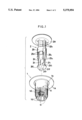
- FIG. 1 is a perspective view of an embodiment of the clip of this invention, showing the male and female members in a non-assembled state;
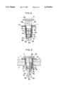
- FIG. 2 is a cross-sectional view of the clip in its provisionally assembled state in which the male member is inserted partway into the female member;
- FIG. 3 is a cross-sectional view of the clip in its fully assembled state.
- Reference numeral 1 denotes a female member formed of synthetic resin.
- a base end flange la extends radially outwardly, from which extends a cylindrical portion 1b that is divided by slits 1c into a plurality of divisions 1d that can be outwardly flexed.
- Each of the divisions 1d narrows toward the end, so that the inside diameter formed by the ends is smaller than the inside diameter of the cylindrical portion 1b and smaller than the inside diameter midway along the divisions 1d.
- Each of the divisions 1d has a projection 1d 1 extending radially inwardly.
- Reference numeral 2 denotes a male member formed with an outside diameter that is slightly smaller than the inside diameter of the cylindrical portion 1b of the female member 1.
- a flange 2a that extends radially outwardly from the base end of the male member 2, a large diameter portion 2b having a plurality of raised portions 2b 1 spaced substantially equidistantly apart around the peripheral surface of the large diameter portion 2b, a small diameter portion 2c, and a head portion 2d having substantially the same outside diameter as that of the large diameter portion 2b.
- the large diameter portion 2b is provided with plural recesses 2b 2 formed around the peripheral surface of the large diameter portion 2b at a prescribed spacing which are capable of engaging the projections 1d 1 formed on the inside surface of the divisions 1d, and tapered portions 2b 3 at the transition portion between the large diameter portion 2b and the small diameter portion 2c.
- a pair of diametrically opposed ribs 2c 1 which extend lengthwise along the small diameter portion 2c.
- the tip of the head portion 2d is conically shaped to facilitate the passage of the head portion 2d through the ends of the divisions 1d.
- the head portion 2d also has a pair of cutaways 2d 1 with a cam guide face 2d 2 which during the insertion of the head portion 2d function to guide the inwardly extending projections 1d 1 to one side of the ribs 2c 1 .
- the cam guide face 2d 2 guides the projections 1d 1 so that the projections 1d 1 are slightly deflected circumferentially toward one side of a rib 2c 1 . This is done by slightly rotating either the male member 2 or the female member 1, whereby the projections 1d 1 are located on the side of a rib 2c 1 , and as a result the ribs 2c 1 are accommodated in a slit 1c between adjacent ribs 2c 1 .
- the ribs 2c 1 are always securely guided into the proper position of accommodation in the slits 1c, whether the male member is inserted from the start with the ribs 2c 1 aligned with the slits 1c or the ribs 2c 1 are just provisionally positioned on the inner surface of the divisions 1d. Therefore, it does not happen that the divisions 1d are outwardly flexed by the abutment of the ribs 2c 1 against the inner surface of the divisions 1d as the male member 2 advances, and that this continues until the provisional assembly state is reached.
- the resilience of the divisions 1d causes them to revert to the original small diameter state.
- the internal projections 1d 1 on the divisions 1d locate on the tapered transition portions 2b 3 between the small diameter portion 2c and the large diameter portion 2b and the ends of the divisions 1d are in engagement with the rear face 2d 3 of the head portion 2d.
- the male member 2 and female member 1 are brought into a state which does not readily permit relative freedom of movement between the two members.
- the male member 2 will be in the state of provisional insertion in the female member 1 illustrated by FIG. 2, which is the state in which the clip is delivered for the particular assembly task concerned.
- the method of attaching a panel or other such member to a fixed panel or the like will now be described with reference to FIG. 3.
- the female member 1 of the semi-assembled clip is inserted into hole 3 1 of a fixed panel 3 via hole 4 1 of the subject panel 4 until the divisions 1d of the female member 1 protrude from the hole 3 1 .
- the divisions 1d are again gradually and uniformly flexed radially outwardly by the tapered portions 2b 3 of the large diameter portion 2b while at the same time the head portion 2d and small diameter portion 2c project from the lower end of the divisions 1d.
- the inward projection extending radially inwardly that is provided on each of the female member flexible divisions are formed on the head portion of the male member, during provisional assembly the ribs can be securely located in the slits between divisions by slightly rotating the male member. This has the effect of preventing defective products caused by the male member continuing to be advanced although ribs are abutting the inner surface of divisions, producing a provisionally assembled clip in which the divisions are in an outwardly flexed state.
Landscapes
- Engineering & Computer Science (AREA)
- General Engineering & Computer Science (AREA)
- Mechanical Engineering (AREA)
- Insertion Pins And Rivets (AREA)
Abstract
A clip comprising a female member and a male member, with the female member having a plurality of resilient divisions, with the end of each division pressing radially inwardly, and in which the male member has a head portion that radially outwardly flexes said divisions, a small diameter portion integrally associated to the rear of the head portion that does not radially outwardly flex the divisions, and a large diameter portion integrally associated to the rear of the small diameter portion that can engage with the ends of the divisions to thereby hold the divisions in a radially outwardly flexed state, and the small diameter portion is also provided with ribs which can be received in the dividing slits used to form the divisions in the female member. As the insertion of the head portion proceeds, a cam surface on a cutaway portion formed on the head portion enables the projections of the divisions to be guided into position on the side of the ribs, whereby the ribs can be located in the slits by slightly rotating the male or female member.
Description
1. Field of the Invention
The present invention relates to a clip of synthetic resin that allows panel members, such as for example the bumper and bumper beam of an automobile, to be fastened together without using nuts and bolts.
2. Description of the Prior Art
There are known clips of this type, such as for example the clip described by Japanese Utility Model Disclosure 61-166212, in which the clip comprises a female member and a male member, with the female member having a plurality of resilient divisions, with the end of each division pressing radially inwardly, and in which the male member has a head portion that radially outwardly flexes said divisions, a small diameter portion integrally associated to the rear of the head portion that does not radially outwardly flex the divisions, and a large diameter portion integrally associated to the rear of the small diameter portion that can engage with the ends of the divisions to thereby hold the divisions in a radially outwardly flexed state, and the small diameter portion is also provided with ribs which can be received in the dividing slits used to form the divisions in the female member.
Prior to use, such a clip is usually maintained in a provisionally assembled state, in which the male member is inserted into the female member to a point where the head portion of the male member has gone beyond the ends of the divisions and the small diameter portion is located in the cylindrical portion of the female member.
To attach a panel or other such member using the clip, the clip is inserted from the side of the panel being attached and the male member is further inserted to cause the large diameter portion of the male member to open out the divisions of the female member, thereby affixing the panel in place. The clip is arranged so that in the affixed state the ends of the divisions of the female member are held in engagement with a groove formed on the large diameter portion with the divisions outwardly flexed by the large diameter portion.
However, for the provisionally assembled state described above it is necessary that the location of the small diameter portion in the space within the divisions of the female member does not cause outward flexing of the divisions. It is for that purpose that the small diameter portion is given its small diameter, and in the prior art ribs have therefore been formed on the small diameter portion with the aim of strengthening the small diameter portion. Also, when the male member is inserted into the female member, it is positioned so that the ribs enter the slits of the cylindrical portion instead of directly abutting the divisions, which would cause the divisions to flex outward.
Thus, a drawback of the conventional arrangement is that in inserting the male member for the provisional assembly, the ribs have to be aligned so that they do not abut against the inner face of the divisions but instead enter the slits, a task which is time-consuming and requires skill to perform.
The object of the present invention is therefore to provide a clip in which the ribs are automatically located in the slits when the male member is inserted into the female member.
In accordance with the present invention, the above object is attained by a clip comprising: a cylindrical female member having a cylindrical portion and a flange extending radially outwardly from a base end of said cylindrical portion, said cylindrical portion being divided by a plurality of radially spaced-apart axial slits into a plurality of flexible divisions, said divisions each having an inward projection extending radially inwardly; and a male member for insertion in said female member, said male member having a head portion that radially outwardly flexes said divisions, a small diameter portion associated rearward of said head portion that does not radially outwardly flex said divisions, and a large diameter portion associated rearward of said small diameter portion that can engage with the inward projections of said divisions to hold said divisions radially outwardly flexed, said male member also having a plurality of ribs formed on said small diameter portion for insertion into said slits, and a cutaway portion having a guiding cam surface formed on said head portion for guiding said projections to one side of said ribs.
In the above clip, the inserted head portion of the male member advancing along the cylindrical portion of the female member radially outwardly flexes the divisions of the cylindrical portion. As the head portion thus advances, a cam surface on a cutaway portion formed on the head portion enables the projections of the divisions to be guided into position on the side of the ribs, whereby the ribs can be located in the slits by slightly rotating the male or female member. Thus, as no alignment is required the clip of this invention can be readily provisionally assembled even by a novice, greatly improving the efficiency of the operation.
Further features of the invention, its nature and various advantages will be more apparent from the accompanying drawings and following detailed description of the invention.
FIG. 1 is a perspective view of an embodiment of the clip of this invention, showing the male and female members in a non-assembled state;
FIG. 2 is a cross-sectional view of the clip in its provisionally assembled state in which the male member is inserted partway into the female member; and
FIG. 3 is a cross-sectional view of the clip in its fully assembled state.
An embodiment of the clip according to this invention will now be described with reference to the drawings.
Reference numeral 1 denotes a female member formed of synthetic resin. A base end flange la extends radially outwardly, from which extends a cylindrical portion 1b that is divided by slits 1c into a plurality of divisions 1d that can be outwardly flexed. Each of the divisions 1d narrows toward the end, so that the inside diameter formed by the ends is smaller than the inside diameter of the cylindrical portion 1b and smaller than the inside diameter midway along the divisions 1d. Each of the divisions 1d has a projection 1d1 extending radially inwardly.
Reference numeral 2 denotes a male member formed with an outside diameter that is slightly smaller than the inside diameter of the cylindrical portion 1b of the female member 1. Forming an integral part of the male member 2 are a flange 2a that extends radially outwardly from the base end of the male member 2, a large diameter portion 2b having a plurality of raised portions 2b1 spaced substantially equidistantly apart around the peripheral surface of the large diameter portion 2b, a small diameter portion 2c, and a head portion 2d having substantially the same outside diameter as that of the large diameter portion 2b.
The large diameter portion 2b is provided with plural recesses 2b2 formed around the peripheral surface of the large diameter portion 2b at a prescribed spacing which are capable of engaging the projections 1d1 formed on the inside surface of the divisions 1d, and tapered portions 2b3 at the transition portion between the large diameter portion 2b and the small diameter portion 2c. Provided on the peripheral surface of the small diameter portion 2c is a pair of diametrically opposed ribs 2c1 which extend lengthwise along the small diameter portion 2c. The tip of the head portion 2d is conically shaped to facilitate the passage of the head portion 2d through the ends of the divisions 1d. The head portion 2d also has a pair of cutaways 2d1 with a cam guide face 2d2 which during the insertion of the head portion 2d function to guide the inwardly extending projections 1d1 to one side of the ribs 2c1.
When the head portion 2d passes the portion with the projections 1d1, the cam guide face 2d2 guides the projections 1d1 so that the projections 1d1 are slightly deflected circumferentially toward one side of a rib 2c1. This is done by slightly rotating either the male member 2 or the female member 1, whereby the projections 1d1 are located on the side of a rib 2c1, and as a result the ribs 2c1 are accommodated in a slit 1c between adjacent ribs 2c1.
The clip according to the above arrangement will now be described with reference to when the clip is provisionally assembled. As the head portion 2d of the male member 2 inserted into the cylindrical portion 1b of the female member 1 advances, it pushes against the projections 1d1 and thereby flexes the divisions 1d radially outwardly. During this process, the cam guide face 2d2 of the cutaways 2d1 guides the projections 1d1 toward the side of one of the ribs 2c1 and by slightly rotating the male member 2 the small diameter portion ribs 2c1 are guided into position in the slits 1c. Thus, the ribs 2c1 are always securely guided into the proper position of accommodation in the slits 1c, whether the male member is inserted from the start with the ribs 2c1 aligned with the slits 1c or the ribs 2c1 are just provisionally positioned on the inner surface of the divisions 1d. Therefore, it does not happen that the divisions 1d are outwardly flexed by the abutment of the ribs 2c1 against the inner surface of the divisions 1d as the male member 2 advances, and that this continues until the provisional assembly state is reached.
When the head portion 2d finally passes the ends of the divisions 1d, the resilience of the divisions 1d causes them to revert to the original small diameter state. In that state, the internal projections 1d1 on the divisions 1d locate on the tapered transition portions 2b3 between the small diameter portion 2c and the large diameter portion 2b and the ends of the divisions 1d are in engagement with the rear face 2d3 of the head portion 2d. Thus, the male member 2 and female member 1 are brought into a state which does not readily permit relative freedom of movement between the two members. When at this point the inserting force is removed, the male member 2 will be in the state of provisional insertion in the female member 1 illustrated by FIG. 2, which is the state in which the clip is delivered for the particular assembly task concerned.
The method of attaching a panel or other such member to a fixed panel or the like will now be described with reference to FIG. 3. The female member 1 of the semi-assembled clip is inserted into hole 31 of a fixed panel 3 via hole 41 of the subject panel 4 until the divisions 1d of the female member 1 protrude from the hole 31. By then pressing the male member 2 into the female member 1 until the flange 1a comes into contact with the flange 2a, the divisions 1d are again gradually and uniformly flexed radially outwardly by the tapered portions 2b3 of the large diameter portion 2b while at the same time the head portion 2d and small diameter portion 2c project from the lower end of the divisions 1d. With the tapered portions 2b3 pushed fully home, the projections 1d1 engage in the recesses 2b2 on the large diameter portion 2b, thereby locking the male member 2 and female member 1 together. In this state the divisions 1d are flexed radially outwardly, locking the curved outer peripheral portions of the divisions 1d against the edge of the hole 31, thereby tightly affixing the panel 4 to the panel 3.
In the clip of this invention, as the cutaways with the cam guide face that serve to guide to the side of the small diameter portion ribs the inward projection extending radially inwardly that is provided on each of the female member flexible divisions, are formed on the head portion of the male member, during provisional assembly the ribs can be securely located in the slits between divisions by slightly rotating the male member. This has the effect of preventing defective products caused by the male member continuing to be advanced although ribs are abutting the inner surface of divisions, producing a provisionally assembled clip in which the divisions are in an outwardly flexed state.
Claims (2)
1. A clip fastener for fixing a fixed member to a stationary member, the clip fastener comprising:
a cylindrical female member having a cylindrical portion and a flange extending radially outwardly from a base end of said cylindrical portion, said cylindrical portion being divided by a plurality of radially spaced-apart axial slits into a plurality of flexible divisions, said divisions each having an inward projection extending radially inwardly from a portion of said division which is midway along a length of said division; and
a male member for insertion in said female member, said male member having a head portion that radially outwardly flexes said divisions, a small diameter portion that is associated rearward of said head portion and that does not radially outwardly flex said divisions, and a large diameter portion that is associated rearwardly of said small diameter portion and that can engage with the inward projections of said divisions to hold said divisions radially outwardly flexed, said male member also having a plurality of ribs formed on said small diameter portion for insertion into said slits, and a cutaway portion having a guiding cam surface formed on said head portion for guiding said projections to one side of said ribs and fitting said ribs into said slits.
2. A clip according to claim 1, wherein said male member has a flange extending radially outwardly from a base end of the male member.
Applications Claiming Priority (2)
| Application Number | Priority Date | Filing Date | Title |
|---|---|---|---|
| JP1992085459U JP2586907Y2 (en) | 1992-11-19 | 1992-11-19 | Coupling clips |
| JP4-85459[U] | 1992-11-19 |
Publications (1)
| Publication Number | Publication Date |
|---|---|
| US5375954A true US5375954A (en) | 1994-12-27 |
Family
ID=13859471
Family Applications (1)
| Application Number | Title | Priority Date | Filing Date |
|---|---|---|---|
| US08/153,965 Expired - Fee Related US5375954A (en) | 1992-11-19 | 1993-11-18 | Clip fastener |
Country Status (2)
| Country | Link |
|---|---|
| US (1) | US5375954A (en) |
| JP (1) | JP2586907Y2 (en) |
Cited By (66)
| Publication number | Priority date | Publication date | Assignee | Title |
|---|---|---|---|---|
| US5562375A (en) * | 1994-11-09 | 1996-10-08 | The United States Of America As Represented By The Administrator Of The National Aeronautics And Space Administration | Push type fastener |
| US5568675A (en) * | 1994-03-29 | 1996-10-29 | Nifco Inc. | Two-piece clip |
| DE19531286A1 (en) * | 1995-08-25 | 1997-02-27 | Opel Adam Ag | Spreading dowel to connect two components |
| US5641255A (en) * | 1994-06-15 | 1997-06-24 | Nifco, Inc. | Clip |
| DE29708112U1 (en) * | 1997-05-05 | 1997-07-24 | United Carr Gmbh Trw | Plastic element |
| US5667184A (en) * | 1994-04-20 | 1997-09-16 | Mitsumi Electric Co., Ltd. | Mounting construction of an elastically pressing member having an engaging part to be fixed to a rod-like member |
| GB2323121A (en) * | 1997-03-12 | 1998-09-16 | Nifco Inc | Clip with engaging mechanism |
| FR2761127A1 (en) * | 1997-03-24 | 1998-09-25 | Itw De France | Insert for fixing articles on surfaces, e.g. blind holes, on motor vehicles, in vehicle assembly lines |
| US5902083A (en) * | 1997-07-22 | 1999-05-11 | Kenmark Industrial Co., Ltd. | Engaging component for cabinet structures |
| US6048147A (en) * | 1998-04-03 | 2000-04-11 | Piolax, Inc. | Fixing clip for fixing attachment member to panel |
| US6089805A (en) * | 1998-03-17 | 2000-07-18 | I.T.W. De France | Device for mounting blind |
| US6135812A (en) * | 1997-11-12 | 2000-10-24 | Harting Kgaa | Electrical contact element |
| WO2000068582A1 (en) * | 1999-05-10 | 2000-11-16 | Trw Carr France | Connecting element |
| US6481942B2 (en) * | 2000-05-29 | 2002-11-19 | Nifco Inc. | Clip |
| US6491328B1 (en) | 2000-03-10 | 2002-12-10 | E. J. Brooks Company | Bin seal and fastener |
| US6511108B1 (en) | 1999-10-07 | 2003-01-28 | E. J. Brooks Company | Locking seal with distortable body |
| US6533515B2 (en) | 2001-07-17 | 2003-03-18 | Illinois Tool Works | Fastener having movable drive pin |
| US6540461B1 (en) * | 2001-10-04 | 2003-04-01 | Kenmark Industrial Co., Ltd. | Retaining member |
| US20040025290A1 (en) * | 2000-11-09 | 2004-02-12 | Walter Novarino | Bump stopper for a mobile part of a car body |
| US20050019130A1 (en) * | 2002-02-22 | 2005-01-27 | Hideki Kanie | Integrally molded clip and method of forming the same |
| US20050091802A1 (en) * | 2003-09-24 | 2005-05-05 | Piolax Inc. | Clip |
| US20050101094A1 (en) * | 2003-11-11 | 2005-05-12 | Kabushiki Kaisha Toshiba | Semiconductor device having trench capacitor and fabrication method for the same |
| US20050163587A1 (en) * | 2004-01-26 | 2005-07-28 | Itw Espana, S.A. | Device for attaching a panel to a support |
| US20060000959A1 (en) * | 2004-07-01 | 2006-01-05 | Hansen Wayne M | Grommet and anchoring structure |
| US20060074421A1 (en) * | 2003-05-08 | 2006-04-06 | Bickley Barry T | Fixation augmentation device and related techniques |
| US20070294865A1 (en) * | 2006-06-01 | 2007-12-27 | Takahiro Sano | Clip comprising a pin and a bush |
| US20080031703A1 (en) * | 2004-05-31 | 2008-02-07 | Takeshi Nakajima | Clip |
| US20090002956A1 (en) * | 2007-06-22 | 2009-01-01 | Hitachi, Ltd. | Power Converter |
| US20100199464A1 (en) * | 2007-09-21 | 2010-08-12 | Newfrey Llc | Trim clip for trim for curtain side air bag |
| US20100324558A1 (en) * | 2002-09-18 | 2010-12-23 | Bickley Barry T | Method and apparatus for securing an object to bone and/or for stabilizing bone |
| US20100329815A1 (en) * | 2009-06-26 | 2010-12-30 | Jackson Jr Nicholas | Trim Panel Retainer Assembly |
| US20110144766A1 (en) * | 2008-06-19 | 2011-06-16 | Shreedhar Kale | Allograft Bone Plugs, Systems and Techniques |
| US20110150598A1 (en) * | 2009-12-22 | 2011-06-23 | Honda Access Corp. | Structure for mounting an attachment for vehicle |
| US20110210223A1 (en) * | 2007-08-09 | 2011-09-01 | Nifco Inc. | Clip and Support Member |
| EP2366590A1 (en) * | 2010-03-18 | 2011-09-21 | TRW Automotive Electronics & Components GmbH | Retaining clip |
| US20110292617A1 (en) * | 2010-05-25 | 2011-12-01 | Lear Corporation | Power module with current sensing |
| WO2012016797A1 (en) * | 2010-08-05 | 2012-02-09 | A. Raymond Et Cie | Expanding rivet |
| US20120057948A1 (en) * | 2010-09-06 | 2012-03-08 | Byung-Kyu Jeon | Rivet bolt |
| US20130071201A1 (en) * | 2010-03-03 | 2013-03-21 | Nifco Inc. | Grommet |
| US20130149066A1 (en) * | 2010-07-01 | 2013-06-13 | Kazuya Handa | Grommet |
| US20130315691A1 (en) * | 2011-01-27 | 2013-11-28 | Illinois Tools Works Inc. | Device for fastening a first component on a second component |
| DE102012016362A1 (en) | 2012-08-17 | 2014-02-20 | Bayerische Motoren Werke Aktiengesellschaft | mounting clip |
| US20140093325A1 (en) * | 2012-09-28 | 2014-04-03 | Honda Giken Kogyo Co., Ltd. | Clip |
| US8878483B2 (en) | 2011-01-14 | 2014-11-04 | Lear Corporation | Electronics unit with current sensing |
| US20150173466A1 (en) * | 2011-11-11 | 2015-06-25 | Nifco Inc. | Clip |
| CN105308334A (en) * | 2013-06-19 | 2016-02-03 | 株式会社利富高 | Mounting tool |
| CN105715129A (en) * | 2014-12-18 | 2016-06-29 | 马勒国际有限公司 | Clip Connection |
| EP3067574A1 (en) * | 2015-03-10 | 2016-09-14 | Newfrey LLC | A clip and fastening structure |
| US20160341232A1 (en) * | 2015-05-19 | 2016-11-24 | Pegitz, Llc | Perforated hardboard grommet & fixture securing system |
| US20170037886A1 (en) * | 2015-08-04 | 2017-02-09 | The Boeing Company | Fastener Installation In Composite Panels With Fastener Insert |
| US20170291558A1 (en) * | 2016-04-06 | 2017-10-12 | Newfrey Llc | Automotive door trim fastener and molding method |
| CN108119454A (en) * | 2016-11-29 | 2018-06-05 | 镇江市丹徒区荣炳欣荣机械厂 | A kind of expansive rivet |
| US10221873B2 (en) * | 2014-08-18 | 2019-03-05 | Illinois Tool Works Inc. | Pin and grommet fastener assembly |
| US10399528B2 (en) * | 2015-03-26 | 2019-09-03 | Toyota Jidosha Kabushiki Kaisha | Fixing clip and fixing structure for fixing a member to be installed using the fixing clip |
| US10507780B2 (en) | 2015-03-26 | 2019-12-17 | Toyota Jidosha Kabushiki Kaisha | Fixing clip and fixing structure for fixing a member to be installed using the fixing clip |
| US20200088226A1 (en) * | 2018-09-15 | 2020-03-19 | Termax Llc | Fastener Clip Assembly with a Dome and Limiters |
| USD905546S1 (en) * | 2019-01-04 | 2020-12-22 | Illinois Tool Works Inc. | Fastener |
| FR3101923A1 (en) * | 2019-10-10 | 2021-04-16 | Psa Automobiles Sa | Indexing with integrated and compact clipping. |
| US20210138973A1 (en) * | 2016-11-08 | 2021-05-13 | Illinois Tool Works Inc. | Fastening clip device configured to secure a door module to a door frame of a vehicle |
| WO2021111055A1 (en) * | 2019-12-05 | 2021-06-10 | A. Raymond Et Cie | Expansion rivet |
| US11346385B2 (en) | 2020-04-06 | 2022-05-31 | Illinois Tool Works Inc. | Grommet |
| US11519446B2 (en) | 2018-11-05 | 2022-12-06 | Illinois Tool Works Inc. | Fastener feedback feature |
| USD972402S1 (en) | 2020-07-10 | 2022-12-13 | Illinois Tool Works Inc. | Grommet |
| US11608849B2 (en) | 2019-01-04 | 2023-03-21 | Illinois Tool Works Inc. | Grommet removal assemblies and methods |
| USD990300S1 (en) | 2021-12-15 | 2023-06-27 | Illinois Tool Works Inc. | Fastener |
| USD991024S1 (en) | 2021-12-15 | 2023-07-04 | Illinois Tool Works Inc. | Fastener |
Families Citing this family (1)
| Publication number | Priority date | Publication date | Assignee | Title |
|---|---|---|---|---|
| JP5840484B2 (en) * | 2011-12-27 | 2016-01-06 | 株式会社ニフコ | clip |
Citations (4)
| Publication number | Priority date | Publication date | Assignee | Title |
|---|---|---|---|---|
| JPS61166212A (en) * | 1985-01-18 | 1986-07-26 | Matsushita Electric Ind Co Ltd | Storage means controller |
| US4840523A (en) * | 1987-07-16 | 1989-06-20 | Nifco, Inc. | Securing device |
| US4952106A (en) * | 1988-09-29 | 1990-08-28 | Nifco, Inc. | Fastener having separate portions for engaging two panels to be secured together |
| US5085545A (en) * | 1985-06-19 | 1992-02-04 | Nifco Inc. | Expansible rivet for securing together overlapped panels |
-
1992
- 1992-11-19 JP JP1992085459U patent/JP2586907Y2/en not_active Expired - Fee Related
-
1993
- 1993-11-18 US US08/153,965 patent/US5375954A/en not_active Expired - Fee Related
Patent Citations (4)
| Publication number | Priority date | Publication date | Assignee | Title |
|---|---|---|---|---|
| JPS61166212A (en) * | 1985-01-18 | 1986-07-26 | Matsushita Electric Ind Co Ltd | Storage means controller |
| US5085545A (en) * | 1985-06-19 | 1992-02-04 | Nifco Inc. | Expansible rivet for securing together overlapped panels |
| US4840523A (en) * | 1987-07-16 | 1989-06-20 | Nifco, Inc. | Securing device |
| US4952106A (en) * | 1988-09-29 | 1990-08-28 | Nifco, Inc. | Fastener having separate portions for engaging two panels to be secured together |
Cited By (98)
| Publication number | Priority date | Publication date | Assignee | Title |
|---|---|---|---|---|
| US5568675A (en) * | 1994-03-29 | 1996-10-29 | Nifco Inc. | Two-piece clip |
| US5667184A (en) * | 1994-04-20 | 1997-09-16 | Mitsumi Electric Co., Ltd. | Mounting construction of an elastically pressing member having an engaging part to be fixed to a rod-like member |
| US5641255A (en) * | 1994-06-15 | 1997-06-24 | Nifco, Inc. | Clip |
| US5562375A (en) * | 1994-11-09 | 1996-10-08 | The United States Of America As Represented By The Administrator Of The National Aeronautics And Space Administration | Push type fastener |
| DE19531286A1 (en) * | 1995-08-25 | 1997-02-27 | Opel Adam Ag | Spreading dowel to connect two components |
| GB2323121A (en) * | 1997-03-12 | 1998-09-16 | Nifco Inc | Clip with engaging mechanism |
| US5850676A (en) * | 1997-03-12 | 1998-12-22 | Nifco Inc. | Clip with engaging mechanism |
| GB2323121B (en) * | 1997-03-12 | 2001-08-08 | Nifco Inc | Clip with engaging mechanism |
| US6196756B1 (en) | 1997-03-24 | 2001-03-06 | Illinois Tool Works Inc. | Releasable fastener assembly for preferred use in a vehicle |
| FR2761127A1 (en) * | 1997-03-24 | 1998-09-25 | Itw De France | Insert for fixing articles on surfaces, e.g. blind holes, on motor vehicles, in vehicle assembly lines |
| DE29708112U1 (en) * | 1997-05-05 | 1997-07-24 | United Carr Gmbh Trw | Plastic element |
| US5902083A (en) * | 1997-07-22 | 1999-05-11 | Kenmark Industrial Co., Ltd. | Engaging component for cabinet structures |
| US6135812A (en) * | 1997-11-12 | 2000-10-24 | Harting Kgaa | Electrical contact element |
| US6089805A (en) * | 1998-03-17 | 2000-07-18 | I.T.W. De France | Device for mounting blind |
| US6048147A (en) * | 1998-04-03 | 2000-04-11 | Piolax, Inc. | Fixing clip for fixing attachment member to panel |
| US6685407B1 (en) * | 1999-05-10 | 2004-02-03 | Trw Carr France | Connecting element comprising two members |
| WO2000068582A1 (en) * | 1999-05-10 | 2000-11-16 | Trw Carr France | Connecting element |
| US6511108B1 (en) | 1999-10-07 | 2003-01-28 | E. J. Brooks Company | Locking seal with distortable body |
| US6491328B1 (en) | 2000-03-10 | 2002-12-10 | E. J. Brooks Company | Bin seal and fastener |
| US6481942B2 (en) * | 2000-05-29 | 2002-11-19 | Nifco Inc. | Clip |
| US20040025290A1 (en) * | 2000-11-09 | 2004-02-12 | Walter Novarino | Bump stopper for a mobile part of a car body |
| US6533515B2 (en) | 2001-07-17 | 2003-03-18 | Illinois Tool Works | Fastener having movable drive pin |
| US6540461B1 (en) * | 2001-10-04 | 2003-04-01 | Kenmark Industrial Co., Ltd. | Retaining member |
| US20050019130A1 (en) * | 2002-02-22 | 2005-01-27 | Hideki Kanie | Integrally molded clip and method of forming the same |
| US7105119B2 (en) | 2002-02-22 | 2006-09-12 | Newfrey Llc | Method of forming integrally molded clip |
| US8506605B2 (en) | 2002-09-18 | 2013-08-13 | Simplicity Orthopedics, Inc. | Method and apparatus for securing an object to bone and/or for stabilizing bone |
| US20100324558A1 (en) * | 2002-09-18 | 2010-12-23 | Bickley Barry T | Method and apparatus for securing an object to bone and/or for stabilizing bone |
| US20060074421A1 (en) * | 2003-05-08 | 2006-04-06 | Bickley Barry T | Fixation augmentation device and related techniques |
| US8419780B2 (en) * | 2003-05-08 | 2013-04-16 | Simplicity Orthopedics, Inc. | Apparatus for securing an implantable object to bone |
| US20050091802A1 (en) * | 2003-09-24 | 2005-05-05 | Piolax Inc. | Clip |
| US7222398B2 (en) * | 2003-09-24 | 2007-05-29 | Piolax Inc. | Clip |
| US20050101094A1 (en) * | 2003-11-11 | 2005-05-12 | Kabushiki Kaisha Toshiba | Semiconductor device having trench capacitor and fabrication method for the same |
| US7237995B2 (en) * | 2004-01-26 | 2007-07-03 | Itw Espana, S.A. | Device for attaching a panel to a support |
| US20050163587A1 (en) * | 2004-01-26 | 2005-07-28 | Itw Espana, S.A. | Device for attaching a panel to a support |
| US7862272B2 (en) * | 2004-05-31 | 2011-01-04 | Piolax Inc. | Clip |
| US20080031703A1 (en) * | 2004-05-31 | 2008-02-07 | Takeshi Nakajima | Clip |
| US7131806B2 (en) * | 2004-07-01 | 2006-11-07 | Illinois Tool Works Inc | Grommet and anchoring structure |
| US20060000959A1 (en) * | 2004-07-01 | 2006-01-05 | Hansen Wayne M | Grommet and anchoring structure |
| US7677850B2 (en) * | 2006-06-01 | 2010-03-16 | Newfrey Llc | Clip comprising a pin and a bush |
| US20070294865A1 (en) * | 2006-06-01 | 2007-12-27 | Takahiro Sano | Clip comprising a pin and a bush |
| US20090002956A1 (en) * | 2007-06-22 | 2009-01-01 | Hitachi, Ltd. | Power Converter |
| US8054633B2 (en) * | 2007-06-22 | 2011-11-08 | Hitachi, Ltd. | Power converter |
| US8794887B2 (en) * | 2007-08-09 | 2014-08-05 | Nifco Inc. | Clip and support member |
| US20110210223A1 (en) * | 2007-08-09 | 2011-09-01 | Nifco Inc. | Clip and Support Member |
| US8316514B2 (en) * | 2007-09-21 | 2012-11-27 | Newfry Llc | Trim clip for trim for curtain side air bag |
| US20100199464A1 (en) * | 2007-09-21 | 2010-08-12 | Newfrey Llc | Trim clip for trim for curtain side air bag |
| US8840677B2 (en) * | 2008-06-19 | 2014-09-23 | DePuy Synthes Products, LLC | Allograft bone plugs, systems and techniques |
| US20110144766A1 (en) * | 2008-06-19 | 2011-06-16 | Shreedhar Kale | Allograft Bone Plugs, Systems and Techniques |
| US20100329815A1 (en) * | 2009-06-26 | 2010-12-30 | Jackson Jr Nicholas | Trim Panel Retainer Assembly |
| US20110150598A1 (en) * | 2009-12-22 | 2011-06-23 | Honda Access Corp. | Structure for mounting an attachment for vehicle |
| US8480160B2 (en) * | 2009-12-22 | 2013-07-09 | Honda Access Corp. | Structure for mounting an attachment for vehicle |
| US9016993B2 (en) * | 2010-03-03 | 2015-04-28 | Nifco Inc. | Grommet |
| US20130071201A1 (en) * | 2010-03-03 | 2013-03-21 | Nifco Inc. | Grommet |
| EP2366590A1 (en) * | 2010-03-18 | 2011-09-21 | TRW Automotive Electronics & Components GmbH | Retaining clip |
| US8482904B2 (en) * | 2010-05-25 | 2013-07-09 | Lear Corporation | Power module with current sensing |
| US20110292617A1 (en) * | 2010-05-25 | 2011-12-01 | Lear Corporation | Power module with current sensing |
| US20130149066A1 (en) * | 2010-07-01 | 2013-06-13 | Kazuya Handa | Grommet |
| US9181968B2 (en) * | 2010-07-01 | 2015-11-10 | Nifco Inc. | Grommet |
| WO2012016797A1 (en) * | 2010-08-05 | 2012-02-09 | A. Raymond Et Cie | Expanding rivet |
| US8961088B2 (en) | 2010-08-05 | 2015-02-24 | A. Raymond et Cie | Expanding rivet |
| US20120057948A1 (en) * | 2010-09-06 | 2012-03-08 | Byung-Kyu Jeon | Rivet bolt |
| US8878483B2 (en) | 2011-01-14 | 2014-11-04 | Lear Corporation | Electronics unit with current sensing |
| US8905692B2 (en) * | 2011-01-27 | 2014-12-09 | Illinois Tool Works Inc. | Device for fastening a first component on a second component |
| US20130315691A1 (en) * | 2011-01-27 | 2013-11-28 | Illinois Tools Works Inc. | Device for fastening a first component on a second component |
| US20150173466A1 (en) * | 2011-11-11 | 2015-06-25 | Nifco Inc. | Clip |
| US9155362B2 (en) * | 2011-11-11 | 2015-10-13 | Nifco Inc. | Clip |
| DE102012016362B4 (en) * | 2012-08-17 | 2018-09-20 | Bayerische Motoren Werke Aktiengesellschaft | mounting clip |
| DE102012016362A1 (en) | 2012-08-17 | 2014-02-20 | Bayerische Motoren Werke Aktiengesellschaft | mounting clip |
| US20140093325A1 (en) * | 2012-09-28 | 2014-04-03 | Honda Giken Kogyo Co., Ltd. | Clip |
| US9347474B2 (en) * | 2012-09-28 | 2016-05-24 | Newfrey Llc | Clip |
| CN105308334A (en) * | 2013-06-19 | 2016-02-03 | 株式会社利富高 | Mounting tool |
| US10221873B2 (en) * | 2014-08-18 | 2019-03-05 | Illinois Tool Works Inc. | Pin and grommet fastener assembly |
| CN105715129A (en) * | 2014-12-18 | 2016-06-29 | 马勒国际有限公司 | Clip Connection |
| US10060463B2 (en) * | 2015-03-10 | 2018-08-28 | Newfrey Llc | Clip and fastening structure |
| EP3067574A1 (en) * | 2015-03-10 | 2016-09-14 | Newfrey LLC | A clip and fastening structure |
| US10507780B2 (en) | 2015-03-26 | 2019-12-17 | Toyota Jidosha Kabushiki Kaisha | Fixing clip and fixing structure for fixing a member to be installed using the fixing clip |
| US10399528B2 (en) * | 2015-03-26 | 2019-09-03 | Toyota Jidosha Kabushiki Kaisha | Fixing clip and fixing structure for fixing a member to be installed using the fixing clip |
| US20160341232A1 (en) * | 2015-05-19 | 2016-11-24 | Pegitz, Llc | Perforated hardboard grommet & fixture securing system |
| US10087978B2 (en) * | 2015-05-19 | 2018-10-02 | Pegitz, Llc | Perforated hardboard grommet and fixture securing system |
| US9850927B2 (en) * | 2015-08-04 | 2017-12-26 | The Boeing Company | Fastener installation in composite panels with fastener insert |
| US20170037886A1 (en) * | 2015-08-04 | 2017-02-09 | The Boeing Company | Fastener Installation In Composite Panels With Fastener Insert |
| US9873388B2 (en) * | 2016-04-06 | 2018-01-23 | Newfrey Llc | Automotive door trim fastener and molding method |
| US20170291558A1 (en) * | 2016-04-06 | 2017-10-12 | Newfrey Llc | Automotive door trim fastener and molding method |
| US20210138973A1 (en) * | 2016-11-08 | 2021-05-13 | Illinois Tool Works Inc. | Fastening clip device configured to secure a door module to a door frame of a vehicle |
| CN108119454A (en) * | 2016-11-29 | 2018-06-05 | 镇江市丹徒区荣炳欣荣机械厂 | A kind of expansive rivet |
| US20200088226A1 (en) * | 2018-09-15 | 2020-03-19 | Termax Llc | Fastener Clip Assembly with a Dome and Limiters |
| US10995783B2 (en) * | 2018-09-15 | 2021-05-04 | Termax Llc | Fastener clip assembly with a dome and limiters |
| US11519446B2 (en) | 2018-11-05 | 2022-12-06 | Illinois Tool Works Inc. | Fastener feedback feature |
| US11608849B2 (en) | 2019-01-04 | 2023-03-21 | Illinois Tool Works Inc. | Grommet removal assemblies and methods |
| USD905546S1 (en) * | 2019-01-04 | 2020-12-22 | Illinois Tool Works Inc. | Fastener |
| FR3101923A1 (en) * | 2019-10-10 | 2021-04-16 | Psa Automobiles Sa | Indexing with integrated and compact clipping. |
| WO2021111055A1 (en) * | 2019-12-05 | 2021-06-10 | A. Raymond Et Cie | Expansion rivet |
| FR3104216A1 (en) * | 2019-12-05 | 2021-06-11 | A. Raymond Et Cie | Expanding rivet |
| US11346385B2 (en) | 2020-04-06 | 2022-05-31 | Illinois Tool Works Inc. | Grommet |
| US11698094B2 (en) | 2020-04-06 | 2023-07-11 | Illinois Tool Works Inc. | Grommet |
| USD972402S1 (en) | 2020-07-10 | 2022-12-13 | Illinois Tool Works Inc. | Grommet |
| USD990300S1 (en) | 2021-12-15 | 2023-06-27 | Illinois Tool Works Inc. | Fastener |
| USD991024S1 (en) | 2021-12-15 | 2023-07-04 | Illinois Tool Works Inc. | Fastener |
Also Published As
| Publication number | Publication date |
|---|---|
| JPH0643317U (en) | 1994-06-07 |
| JP2586907Y2 (en) | 1998-12-14 |
Similar Documents
| Publication | Publication Date | Title |
|---|---|---|
| US5375954A (en) | Clip fastener | |
| US4874276A (en) | Fastener | |
| US5695296A (en) | Connector for plates | |
| US4952106A (en) | Fastener having separate portions for engaging two panels to be secured together | |
| US5632581A (en) | Clip | |
| US20050034282A1 (en) | Component connection system | |
| US6896460B2 (en) | Fastener | |
| US8926244B2 (en) | Member fastening structure and clip for fastening member | |
| US7549829B2 (en) | Clip | |
| JP2578069Y2 (en) | Grommet | |
| US4668145A (en) | Fastener for coupling together two panels in face-to-face relation | |
| US4648766A (en) | Plastic fastener for detachably mounting a panel on a support member | |
| US5261707A (en) | Joint for connection of a corrugated pipe | |
| JPS636207A (en) | Push-in fastener made of plastic | |
| GB2335951A (en) | Panel fixing clip comprising grommet, pin and flexible seal cap | |
| US4821381A (en) | Fastener made of synthetic resin | |
| US11739782B2 (en) | Quick—disconnect fastening system | |
| GB2082668A (en) | Two part fastener | |
| US4334813A (en) | Device for fastening an object against a wall or the like | |
| EP0185394B1 (en) | Fastener | |
| JP3332138B2 (en) | clip | |
| GB2305961A (en) | A releasable clip or rivet having a segmented leg expandable by an insertion pin | |
| US5605424A (en) | Two-part fastening system | |
| JP3895826B2 (en) | Member mounting structure | |
| JP2996453B2 (en) | Furniture fixing device |
Legal Events
| Date | Code | Title | Description |
|---|---|---|---|
| LAPS | Lapse for failure to pay maintenance fees | ||
| FP | Lapsed due to failure to pay maintenance fee |
Effective date: 19981227 |
|
| STCH | Information on status: patent discontinuation |
Free format text: PATENT EXPIRED DUE TO NONPAYMENT OF MAINTENANCE FEES UNDER 37 CFR 1.362 |