US5357869A - Device for facilitating access to a rail vehicle having extendable ramp assembly - Google Patents
Device for facilitating access to a rail vehicle having extendable ramp assembly Download PDFInfo
- Publication number
- US5357869A US5357869A US08/083,260 US8326093A US5357869A US 5357869 A US5357869 A US 5357869A US 8326093 A US8326093 A US 8326093A US 5357869 A US5357869 A US 5357869A
- Authority
- US
- United States
- Prior art keywords
- board
- doorsill
- entrance
- vehicle
- extended position
- Prior art date
- Legal status (The legal status is an assumption and is not a legal conclusion. Google has not performed a legal analysis and makes no representation as to the accuracy of the status listed.)
- Expired - Lifetime
Links
Images


Classifications
-
- A—HUMAN NECESSITIES
- A61—MEDICAL OR VETERINARY SCIENCE; HYGIENE
- A61G—TRANSPORT, PERSONAL CONVEYANCES, OR ACCOMMODATION SPECIALLY ADAPTED FOR PATIENTS OR DISABLED PERSONS; OPERATING TABLES OR CHAIRS; CHAIRS FOR DENTISTRY; FUNERAL DEVICES
- A61G3/00—Ambulance aspects of vehicles; Vehicles with special provisions for transporting patients or disabled persons, or their personal conveyances, e.g. for facilitating access of, or for loading, wheelchairs
- A61G3/02—Loading or unloading personal conveyances; Facilitating access of patients or disabled persons to, or exit from, vehicles
- A61G3/06—Transfer using ramps, lifts or the like
- A61G3/061—Transfer using ramps, lifts or the like using ramps
-
- B—PERFORMING OPERATIONS; TRANSPORTING
- B61—RAILWAYS
- B61D—BODY DETAILS OR KINDS OF RAILWAY VEHICLES
- B61D23/00—Construction of steps for railway vehicles
-
- A—HUMAN NECESSITIES
- A61—MEDICAL OR VETERINARY SCIENCE; HYGIENE
- A61G—TRANSPORT, PERSONAL CONVEYANCES, OR ACCOMMODATION SPECIALLY ADAPTED FOR PATIENTS OR DISABLED PERSONS; OPERATING TABLES OR CHAIRS; CHAIRS FOR DENTISTRY; FUNERAL DEVICES
- A61G3/00—Ambulance aspects of vehicles; Vehicles with special provisions for transporting patients or disabled persons, or their personal conveyances, e.g. for facilitating access of, or for loading, wheelchairs
- A61G3/02—Loading or unloading personal conveyances; Facilitating access of patients or disabled persons to, or exit from, vehicles
- A61G3/06—Transfer using ramps, lifts or the like
- A61G3/067—Transfer using ramps, lifts or the like with compartment for horizontally storing the ramp or lift
-
- B—PERFORMING OPERATIONS; TRANSPORTING
- B61—RAILWAYS
- B61D—BODY DETAILS OR KINDS OF RAILWAY VEHICLES
- B61D23/00—Construction of steps for railway vehicles
- B61D23/02—Folding steps for railway vehicles, e.g. hand or mechanically actuated
-
- Y—GENERAL TAGGING OF NEW TECHNOLOGICAL DEVELOPMENTS; GENERAL TAGGING OF CROSS-SECTIONAL TECHNOLOGIES SPANNING OVER SEVERAL SECTIONS OF THE IPC; TECHNICAL SUBJECTS COVERED BY FORMER USPC CROSS-REFERENCE ART COLLECTIONS [XRACs] AND DIGESTS
- Y02—TECHNOLOGIES OR APPLICATIONS FOR MITIGATION OR ADAPTATION AGAINST CLIMATE CHANGE
- Y02T—CLIMATE CHANGE MITIGATION TECHNOLOGIES RELATED TO TRANSPORTATION
- Y02T30/00—Transportation of goods or passengers via railways, e.g. energy recovery or reducing air resistance
-
- Y—GENERAL TAGGING OF NEW TECHNOLOGICAL DEVELOPMENTS; GENERAL TAGGING OF CROSS-SECTIONAL TECHNOLOGIES SPANNING OVER SEVERAL SECTIONS OF THE IPC; TECHNICAL SUBJECTS COVERED BY FORMER USPC CROSS-REFERENCE ART COLLECTIONS [XRACs] AND DIGESTS
- Y10—TECHNICAL SUBJECTS COVERED BY FORMER USPC
- Y10S—TECHNICAL SUBJECTS COVERED BY FORMER USPC CROSS-REFERENCE ART COLLECTIONS [XRACs] AND DIGESTS
- Y10S414/00—Material or article handling
- Y10S414/134—Handicapped person handling
Definitions
- the present invention relates to a device for facilitating access to a rail vehicle while stopped at a station, in particular for people having difficulty with mobility, handicapped people in wheelchairs, or people travelling with baggage on wheels.
- Document FR-A-2 587 667 describes a device giving easy access to rail vehicles while stopped at a station and including a doorsill and a board forming a loading ramp.
- the doorsill and the board are hinged between two extreme positions: a folded position in which the vehicle can run, and an unfolded position giving access to the vehicle.
- the doorsill In the folded position, the doorsill is in a horizontal position and constitutes a portion of the floor of the vehicle.
- the doorsill and the board are inclined, with the board resting against the platform.
- the device when in the unfolded position, has a slope of about 20%. Such a high figure is no longer acceptable, and railway operators are now tending to set a maximum figure of 10%.
- the housing for the device in the vehicle occupies a large amount of vertical space that requires a cutout to be formed in the vehicle frame. This reduces the strength of the frame and consequently it reduces passenger safety.
- the device includes a hinged doorsill which, while the vehicle is running, constitutes a source of draughts and gives rise to problems of sealing. As a result, the device cannot be used in high speed trains whose access doors are fitted with inflatable gaskets for combatting phenomena due to pressure waves.
- a device of the same kind is described in FR-A-35 2 416 136.
- That device comprises an access ramp to the vehicle and capable of moving between a retracted position in which its outer portion constitutes a conventional type of step, and an extended position enabling handicapped people to gain access to the vehicle.
- the device also includes members for controlling the extending and retracting movements of the access ramp. That device suffers from the same drawbacks as those specified for document FR-A-2 587 667.
- the access device of the invention serves to mitigate the above drawbacks.
- In the unfolded position it has a slope of less than 10%. It occupies a small amount of vertical space, thus making it possible to house it in the floor of the vehicle without making a cutout in the frame of the vehicle. It does not include a hinged doorsill, thereby making it suitable for use in high speed trains.
- the present invention therefore provides a device for facilitating access to a rail vehicle, the device comprising a board that is movable between a retracted position in which it is housed beneath the top face of the floor of the vehicle and an extended position in which it constitutes an access ramp between a platform and an entrance doorsill of the vehicle, the device including drive means for driving the board and means for stopping translation of the board in its extended position, wherein the drive means are disposed in the plane of the board, the device including means for tilting the board about means for stopping the board's movement in translation so that the outside end of the board rests on the platform and so that the board cooperates with the entrance doorsill to provide a continuous surface without any offset, the entrance doorsill remaining stationary.
- the drive means comprise a rodless actuator having a slide that is driven by magnetic coupling.
- the drive means may be connected to the board by links.
- the means for stopping translation movement of the board may comprise a rod disposed transversely relative to the board, the board being fitted with retaining means that engage the rod to limit the stroke of the board in the extended position.
- the board may comprise a plate constituting said access ramp and a portion situated in a plane different from that of the plate, the connection between the plate and said portion forming a fork to constitute said retaining means.
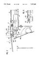
- FIG. 1 is a side view of the board of the access device of the invention in position on a station platform;
- FIG. 2 is a plan view corresponding to FIG. 1 with a portion of the rail vehicle removed to show the drive members;
- FIG. 3 is a view of a detail of FIG. 1 on a larger scale
- FIG. 4 is a view of a detail of FIG. 2 on a larger scale
- FIGS. 5, 6, and 7 are side views showing the board of the device of the invention.
- FIG. 8 shows a detail of FIG. 3.
- FIGS. 1 and 2 show the board 1 in its fully deployed state, so that its outer end rests on the platform 2. It gives access to the inside of the rail vehicle 3 whose door 4 can be seen in the open position.
- the board co-operates with the entrance doorsill 5 of the vehicle to form a continuous surface without any step or offset.
- the doorsill 5 remains stationary and provides continuity with the top face 6 of the floor 7 of the vehicle.
- the floor is supported on the frame 8 which does not include a cutout, since the device of the invention is housed fully within the thickness of the floor.
- the major portion of the board 1 is constituted by a rectangular plate 9 whose end adjacent to the doorsill 5, when the board is fully deployed, is slightly curved and is extended by lateral elements 10 and 11 and by central elements 12 and 13. These lateral and central elements are situated in a plane that is parallel to and below that of the board 1.
- the lateral elements 10 and 11 serve to guide the board.
- the central elements 12 and 13 serve to drive it.
- the board may be driven by means of a linear pneumatic drive actuator without a piston rod and making use of magnetic coupling, e.g. of the type sold by the FESTO Company.
- FIGS. 1 and 2 there can be seen the drive actuator 14 which is fixed at its ends to brackets 5 and 16 parallel to the main axis of the vehicle.
- the axis of the actuator 14 is thus perpendicular to the entrance to the vehicle.
- a slider 17 is capable of sliding along the actuator 14 under magnetic coupling.
- the central elements 12 and 13 of the board 1 are disposed on either side of the slider 17. Links 18 and 19 connect these central elements to the slider.
- the board is guided for deployment and retraction purposes along slideways 20 and 21 disposed beneath the floor of the vehicle. These slideways are open towards the inside of the device to allow wheels 22 (see FIG. 2) and 23 (see FIG. 3) to run therealong, which wheels are carried on the outsides of the lateral elements 10 and 11.
- the device also includes two rocking arms on either side of the board and mounted on the uprights of the door opening. These rocking arms can be seen more clearly in FIG. 3 which is an enlarged view of FIG. 1. They are rotatable about the axis 25 about which they are fixed to the door uprights. The rocking arms are connected together by a rod 26 supporting load-carrying wheels 27 at its ends. While it is being deployed, the board is thus guided horizontally by the slideways 20 and 21 and bears continuously on the load-carrying wheels 27.
- the door of the vehicle and the board may operate simultaneously, in alternation, or independently. However, in order to minimize time lost in a station, it is preferable for the door and board displacement stages to be related to each other.
- the board On arrival in a station, the board is extended and then the vehicle door is opened, with the door providing access only once the board has been placed on the platform.
- the door On leaving a station, the door is closed initially and then once the door prevents access, the board begins to be retracted. Thereafter both the door and the board finish off their respective strokes.
- the board is thus movable between two extreme positions: a horizontal position during vehicle travel; and an inclined position where it constitutes a continuous ramp giving access to the vehicle.
- a protective flap 28 completely masks the board and its guide and drive mechanism while the vehicle is moving.
- the access device is reversible thus making it possible, in the event of a breakdown, to retract the board by hand after pneumatically isolating the actuator control motor.
- the lateral portions of the board include specialized zones that can be seen in FIGS. 2 and 4. They comprise load-carrying tracks 29 and stabilizing tracks 30 formed beneath the plate 9 of the board.
- the load-carrying tracks 29 allow the board to run over the load-carrying wheels 27. They are constituted by a plane surface as can be seen in FIG. 5 which is a section through the board on axis V--V of FIG. 4.
- the tracks 30 and gear wheels 31 carried by the rod 26 serve to stabilize the board during its deployment and retraction movements. They are constituted by racks 32 that mesh with the gear wheels 31, as can be seen in FIG. 6 which is a section through the board on line VI--VI of FIG. 4.
- the central portion of the board includes stiffeners 33 as shown in FIG. 7 which is a section through the board on line VII--VII of FIG. 4.
- the device operates as follows. On stopping in a station, the rodless actuator 14 is energized to push the board 1 out from the vehicle by means of the slider 17 and the links 18 and 19. The board then moves horizontally as shown by dashed lines in FIG. 1.
- the protective flap 28 opens to allow the board to move past.
- the flap 28 is opened by push rods 34 (see FIGS. 2, 3, and 4) terminated by wheels 35.
- the push rods 34 slide in holes formed through the bracket 15 (adjacent to the vehicle door) and through supports 36 (on the inside of the vehicle).
- the corresponding end of each rod 34 includes a retaining element for retaining the rod.
- the stroke possible for these rods is constituted by the distance between their rear ends and the bracket 16.
- the rods have respective collars 37 and a spring 38 is disposed between each collar and the support 36 corresponding to the rod. In this way, the rods are subjected to thrust that tends to cause the flap to open.
- abutments 39 secured to the board act on the spring 38 and cause the rods 34 to be withdrawn.
- a spring (not shown) then causes the flap 28 to close.
- the abutments 39 quickly release the springs 38 and the rods 34 force the flap 28 to open.
- FIG. 8 which is a detailed view of FIG. 3 shows this stage in deployment of the board.
- the actuator, the slider, the links, and the central elements of the board are omitted, thereby making it possible to see the wheel 23 carried by the lateral element 10 in the vertical recess 40 of the slideway 20.
- the board slopes under the effect of gravity.
- the vehicle door opens while the drive mechanism continues to push the board outwards.
- the forks of the board then push the rod 26 so as to rock the rocking arms 24.
- the rod 26 and the rocking arms 24 constitute members for stopping the board's movement in translation and for allowing it to tilt so that the outside end of the board rests on the platform. It may also be observed that the board runs continuously without any offset into the entrance doorsill 5.
- FIGS. 1, 3, 5, and 7 show that the forks of the board are constituted by the connection zone between the plate 9 and the lateral and central elements 10, 11, 12, and 13, said lateral essential elements extending the board forwards in the form of fingers that are parallel to the plate.
- FIG. 3 shows the finger 42 corresponding to the central element 13 and FIG. 7 shows the finger 41 corresponding to the lateral element 11.
- the door closes and the actuator is energized in the opposite direction, thereby causing the board to be retracted into the vehicle.
- the device of the invention makes it possible to reduce embarkation time compared with prior art ramp type systems since the board is extended and retracted, in part, while the door is being operated. It will be observed that this device includes a minimum number of moving parts and that they are of small mass, thereby enabling energy consumption to be reduced. This also leads to better safety for people and for equipment, to increased reliability, to reduced wear and maintenance, and to reduced operating costs. When working under fault conditions, it is easy to operate the device manually.
- the modular drawer-type design of the device makes it easy to replace it as a whole. The door can be operated and access obtained to the vehicle even when the board is out of operation.
- a rodless actuator reduces the bulk of the device, for an actuator of similar length and stroke.
- the absence of a rod reduces moving mass.
- the actuator reaches the end of its stroke without making contact, because of magnetic detection.
- This rodless actuator is easily adapted to the lengths and strokes applicable in each case.
- the forces provided for extending and retracting the board are equivalent. There is no risk of leakage.
Landscapes
- Health & Medical Sciences (AREA)
- Public Health (AREA)
- Life Sciences & Earth Sciences (AREA)
- Animal Behavior & Ethology (AREA)
- General Health & Medical Sciences (AREA)
- Veterinary Medicine (AREA)
- Engineering & Computer Science (AREA)
- Mechanical Engineering (AREA)
- Platform Screen Doors And Railroad Systems (AREA)
- Vehicle Step Arrangements And Article Storage (AREA)
- Automatic Cycles, And Cycles In General (AREA)
- Auxiliary Methods And Devices For Loading And Unloading (AREA)
- Seats For Vehicles (AREA)
- Automotive Seat Belt Assembly (AREA)
- Loading Or Unloading Of Vehicles (AREA)
- Power-Operated Mechanisms For Wings (AREA)
- Forklifts And Lifting Vehicles (AREA)
- Electrical Discharge Machining, Electrochemical Machining, And Combined Machining (AREA)
Abstract
Description
Claims (2)
Applications Claiming Priority (2)
| Application Number | Priority Date | Filing Date | Title |
|---|---|---|---|
| FR9208611 | 1992-07-10 | ||
| FR9208611A FR2693421B1 (en) | 1992-07-10 | 1992-07-10 | Device facilitating access to a rail vehicle. |
Publications (1)
| Publication Number | Publication Date |
|---|---|
| US5357869A true US5357869A (en) | 1994-10-25 |
Family
ID=9431809
Family Applications (1)
| Application Number | Title | Priority Date | Filing Date |
|---|---|---|---|
| US08/083,260 Expired - Lifetime US5357869A (en) | 1992-07-10 | 1993-06-29 | Device for facilitating access to a rail vehicle having extendable ramp assembly |
Country Status (10)
| Country | Link |
|---|---|
| US (1) | US5357869A (en) |
| EP (1) | EP0578574B1 (en) |
| KR (1) | KR100260565B1 (en) |
| AT (1) | ATE142473T1 (en) |
| CA (1) | CA2100180C (en) |
| DE (1) | DE69304628T2 (en) |
| DK (1) | DK0578574T3 (en) |
| ES (1) | ES2091572T3 (en) |
| FR (1) | FR2693421B1 (en) |
| GR (1) | GR3021698T3 (en) |
Cited By (37)
| Publication number | Priority date | Publication date | Assignee | Title |
|---|---|---|---|---|
| US5775232A (en) * | 1997-02-14 | 1998-07-07 | Vapor Corporation | Bridge plate for a mass transit vehicle |
| WO1999048458A1 (en) * | 1998-03-26 | 1999-09-30 | Daimlerchrysler Ag | A lifting device for railway vehicles |
| US6167816B1 (en) | 1998-06-05 | 2001-01-02 | Westinghouse Air Brake Company | Single screw bridgeplate |
| US6186733B1 (en) * | 1998-04-15 | 2001-02-13 | Lift-U, Division Of Hogan Mfg., Inc. | Low floor vehicle ramp assembly |
| US6203265B1 (en) * | 1998-04-15 | 2001-03-20 | Lift-U, Division Of Hogan Mfg., Inc. | Ramp assembly with lifting levers |
| EP1121920A2 (en) * | 2000-01-31 | 2001-08-08 | S.A. Masats | Retractable ramp suitable for motor vehicles |
| US6352034B1 (en) * | 1999-01-11 | 2002-03-05 | Bolliger & Mabillard Ingenieurs Conseils S.A. | Installation for amusement park, installation referred to as roller coaster |
| WO2002079018A1 (en) * | 2001-03-28 | 2002-10-10 | Neville Rail Projects Limited | Bridge |
| US20030090081A1 (en) * | 2001-11-12 | 2003-05-15 | Oakley Robert L. | Passenger ingress and egress system for transit vehicle |
| US6655905B1 (en) * | 2002-06-04 | 2003-12-02 | Volunteers For Medical Engineering | Linear translation device |
| US20040013507A1 (en) * | 2001-08-22 | 2004-01-22 | Aaron Kiser | Wheelchair ramp with side barriers |
| KR100415624B1 (en) * | 2001-08-02 | 2004-01-24 | 김동건 | An operating apparatus of subsidiary stool for entrance of electric railcar |
| US20040211336A1 (en) * | 2003-03-19 | 2004-10-28 | Westinghouse Air Brake Technologies Corporation | High/low passenger ingress and egress conversion for transit vehicle |
| KR100492479B1 (en) * | 2002-06-28 | 2005-05-30 | 원충연 | Subway safety stool system |
| US20050215371A1 (en) * | 2001-01-26 | 2005-09-29 | The Braun Corporation | Drive mechanism for a vehicle access system |
| US20050217533A1 (en) * | 2004-02-04 | 2005-10-06 | Alstom Transport S.A. | Door threshold for access to the interior of a railway vehicle |
| US20060181099A1 (en) * | 2003-03-06 | 2006-08-17 | Algonquin Automotive | Motorized rack and pinion assembly |
| US20080134930A1 (en) * | 2006-12-07 | 2008-06-12 | Drago Joseph J | Train car compensator for platform gap spacing |
| US20080271268A1 (en) * | 2007-05-04 | 2008-11-06 | Lift-U, Division Of Hogan Mfg., Inc. | Articulating close out assembly for a fold out ramp |
| US20080276832A1 (en) * | 2007-05-11 | 2008-11-13 | Chisena Michael P | Train-to-platform gap mitigator |
| US20090090266A1 (en) * | 2007-07-02 | 2009-04-09 | Alstom Transport Sa | Railway vehicle and device for accessing said vehicle |
| US20090106918A1 (en) * | 2007-10-30 | 2009-04-30 | Marshall Elevator Company | Retractable Ramp |
| US20100043664A1 (en) * | 2006-10-03 | 2010-02-25 | Kaba Gilgen Ag | Gap-Bridging Device for Train Platforms |
| US20100058949A1 (en) * | 2006-10-30 | 2010-03-11 | Regie Autonome Des Transports Parisiens | Device for bridging a gap between a platform and a rail vehicle |
| US8020496B1 (en) * | 2008-03-17 | 2011-09-20 | Ignacio Maysonet | Retractable platform device for use with subway trains and associated method |
| US8028629B2 (en) | 1999-07-08 | 2011-10-04 | Aai Corporation | Passenger rail car sliding door with high platform threshold |
| DE202012000642U1 (en) | 2012-01-23 | 2012-02-27 | Policske Strojirny A.S. | Entry lift for means of transport with lateral driveway for a wheelchair |
| CN104936847A (en) * | 2013-01-14 | 2015-09-23 | 克诺尔-布里姆斯股份有限公司 | Entry aid with three-point bearing for rail vehicle or motor vehicle |
| DE102015203301A1 (en) * | 2015-02-24 | 2016-08-25 | Bombardier Transportation Gmbh | Rail vehicle car body with entry module |
| US20170044819A1 (en) * | 2014-05-02 | 2017-02-16 | Siemens Aktiengesellschaft | Pressure-Sealed Door For A High-Speed Rail Vehicle |
| US9598090B1 (en) | 2014-01-28 | 2017-03-21 | Ignacio R. Maysonet | Vertically retractable safety platform system for use with subway trains and associated method |
| US10071752B2 (en) * | 2014-04-07 | 2018-09-11 | Knorr-Bremse Gmbh | Movable footboard for a vehicle door |
| CN109184420A (en) * | 2018-11-06 | 2019-01-11 | 西南交通大学 | From the door control system of traveling equipment launch train |
| US10835832B2 (en) | 2019-03-31 | 2020-11-17 | Universal City Studio LLC | Gap covering systems and methods for amusement park attractions |
| CN112977508A (en) * | 2021-03-01 | 2021-06-18 | 中车青岛四方机车车辆股份有限公司 | Transmission device, rail vehicle and transportation hub |
| CN112977514A (en) * | 2021-03-01 | 2021-06-18 | 中车青岛四方机车车辆股份有限公司 | Transmission and rail vehicle |
| US11554721B2 (en) * | 2016-12-17 | 2023-01-17 | Knorr-Bremse Gesellscaft mit beschränkter Haftung | Sliding step assembly for a motor vehicle or for a rail vehicle |
Families Citing this family (9)
| Publication number | Priority date | Publication date | Assignee | Title |
|---|---|---|---|---|
| DE4422598C2 (en) * | 1994-06-28 | 1998-09-10 | Ibeg Masch & Geraetebau | Ascent and descent ramp for public transport |
| DE19503079C2 (en) * | 1995-02-01 | 1998-07-09 | Deutsche Waggonbau Ag | Drive-over ramp for wheelchair users in vehicles with low-floor entrances, especially passenger coaches |
| US5832555A (en) * | 1995-02-27 | 1998-11-10 | Ricon Corporation | Compact moveable ramp assembly |
| DE19531284A1 (en) * | 1995-08-25 | 1997-02-27 | Abb Patent Gmbh | Passenger railway vehicle with retracted steps for access to platform |
| EP0931532A1 (en) * | 1998-01-28 | 1999-07-28 | IFE Industrie-Einrichtungen Fertigungs-Aktiengesellschaft | Ramp for vehicles |
| FR2944955B1 (en) * | 2009-04-29 | 2012-12-14 | Metalic | RETRACTABLE RAMP FOR ACCESSING A VEHICLE |
| KR101325118B1 (en) | 2012-02-02 | 2013-11-06 | (사)한국철도차량엔지니어링 | Fixing Apparatus for Moving Body |
| DE102016125785B4 (en) | 2016-12-28 | 2018-07-19 | Bombardier Transportation Gmbh | Door device for a rail vehicle |
| AT519944B1 (en) * | 2017-05-11 | 2019-02-15 | Siemens Ag Oesterreich | gap filling |
Citations (11)
| Publication number | Priority date | Publication date | Assignee | Title |
|---|---|---|---|---|
| BE363516A (en) * | ||||
| US3730361A (en) * | 1971-07-28 | 1973-05-01 | Zink R | Vehicle ramp |
| US3870170A (en) * | 1973-06-06 | 1975-03-11 | Donald E Noble | Loading ramp for pick-up trucks and the like |
| US4131209A (en) * | 1977-08-18 | 1978-12-26 | Manning Donald L | Vehicle entrance ramp |
| US4188889A (en) * | 1977-10-13 | 1980-02-19 | Faiveley S.A. | Retractable running-board, especially for a railway car door |
| WO1980001266A1 (en) * | 1978-12-19 | 1980-06-26 | D Manning | Vehicle entrance ramp |
| US4369984A (en) * | 1979-11-17 | 1983-01-25 | Maschinenfabrik Augsburg-Nurnberg Aktiengesellschaft | Passenger vehicle such as a bus having a laterally extending stair assembly |
| US4759682A (en) * | 1987-05-06 | 1988-07-26 | Transpec Inc. | Vehicle entrance ramp |
| US4850788A (en) * | 1987-07-13 | 1989-07-25 | Dickson Industries, Inc. | Ramp assembly for trailers and the like |
| NL9001113A (en) * | 1990-05-09 | 1991-12-02 | Johannes Jacobus Maria Peters | Access plate for side of rail vehicle - has underfloor plate extensible onto platform at each side |
| US5160236A (en) * | 1991-07-31 | 1992-11-03 | Redding Edward M | Retractable van side door ramp |
Family Cites Families (1)
| Publication number | Priority date | Publication date | Assignee | Title |
|---|---|---|---|---|
| DE3931361C1 (en) * | 1989-09-20 | 1990-10-25 | Mercedes-Benz Aktiengesellschaft, 7000 Stuttgart, De |
-
1992
- 1992-07-10 FR FR9208611A patent/FR2693421B1/en not_active Expired - Fee Related
-
1993
- 1993-06-29 US US08/083,260 patent/US5357869A/en not_active Expired - Lifetime
- 1993-07-07 ES ES93401769T patent/ES2091572T3/en not_active Expired - Lifetime
- 1993-07-07 AT AT93401769T patent/ATE142473T1/en not_active IP Right Cessation
- 1993-07-07 DE DE69304628T patent/DE69304628T2/en not_active Expired - Fee Related
- 1993-07-07 DK DK93401769.0T patent/DK0578574T3/en active
- 1993-07-07 EP EP93401769A patent/EP0578574B1/en not_active Expired - Lifetime
- 1993-07-09 KR KR1019930012905A patent/KR100260565B1/en not_active IP Right Cessation
- 1993-07-09 CA CA002100180A patent/CA2100180C/en not_active Expired - Fee Related
-
1996
- 1996-11-18 GR GR960403085T patent/GR3021698T3/en unknown
Patent Citations (11)
| Publication number | Priority date | Publication date | Assignee | Title |
|---|---|---|---|---|
| BE363516A (en) * | ||||
| US3730361A (en) * | 1971-07-28 | 1973-05-01 | Zink R | Vehicle ramp |
| US3870170A (en) * | 1973-06-06 | 1975-03-11 | Donald E Noble | Loading ramp for pick-up trucks and the like |
| US4131209A (en) * | 1977-08-18 | 1978-12-26 | Manning Donald L | Vehicle entrance ramp |
| US4188889A (en) * | 1977-10-13 | 1980-02-19 | Faiveley S.A. | Retractable running-board, especially for a railway car door |
| WO1980001266A1 (en) * | 1978-12-19 | 1980-06-26 | D Manning | Vehicle entrance ramp |
| US4369984A (en) * | 1979-11-17 | 1983-01-25 | Maschinenfabrik Augsburg-Nurnberg Aktiengesellschaft | Passenger vehicle such as a bus having a laterally extending stair assembly |
| US4759682A (en) * | 1987-05-06 | 1988-07-26 | Transpec Inc. | Vehicle entrance ramp |
| US4850788A (en) * | 1987-07-13 | 1989-07-25 | Dickson Industries, Inc. | Ramp assembly for trailers and the like |
| NL9001113A (en) * | 1990-05-09 | 1991-12-02 | Johannes Jacobus Maria Peters | Access plate for side of rail vehicle - has underfloor plate extensible onto platform at each side |
| US5160236A (en) * | 1991-07-31 | 1992-11-03 | Redding Edward M | Retractable van side door ramp |
Cited By (60)
| Publication number | Priority date | Publication date | Assignee | Title |
|---|---|---|---|---|
| US5775232A (en) * | 1997-02-14 | 1998-07-07 | Vapor Corporation | Bridge plate for a mass transit vehicle |
| US6599080B1 (en) | 1998-03-26 | 2003-07-29 | Daimler Chrysler Ag | Lifting device for railway vehicles |
| WO1999048458A1 (en) * | 1998-03-26 | 1999-09-30 | Daimlerchrysler Ag | A lifting device for railway vehicles |
| AU746046B2 (en) * | 1998-03-26 | 2002-04-11 | Bombardier Transportation Gmbh | A lifting device for railway vehicles |
| US6186733B1 (en) * | 1998-04-15 | 2001-02-13 | Lift-U, Division Of Hogan Mfg., Inc. | Low floor vehicle ramp assembly |
| US6203265B1 (en) * | 1998-04-15 | 2001-03-20 | Lift-U, Division Of Hogan Mfg., Inc. | Ramp assembly with lifting levers |
| US6238168B1 (en) | 1998-04-15 | 2001-05-29 | Lift-U, Division Of Hogan Mfg. | Ramp assembly with locking mechanisms |
| US6409458B1 (en) | 1998-04-15 | 2002-06-25 | Lift-U, Division Of Hogan Mfg., Inc. | Low floor vehicle ramp assembly |
| US6167816B1 (en) | 1998-06-05 | 2001-01-02 | Westinghouse Air Brake Company | Single screw bridgeplate |
| US6352034B1 (en) * | 1999-01-11 | 2002-03-05 | Bolliger & Mabillard Ingenieurs Conseils S.A. | Installation for amusement park, installation referred to as roller coaster |
| JP2010029705A (en) * | 1999-01-11 | 2010-02-12 | Bolliger & Mabillard Ingenier Conseil Sa | Roller coaster type amusement park |
| US8413591B2 (en) | 1999-07-08 | 2013-04-09 | Aai Corporation | Passenger rail car sliding door with high platform threshold |
| US8028629B2 (en) | 1999-07-08 | 2011-10-04 | Aai Corporation | Passenger rail car sliding door with high platform threshold |
| EP1121920A3 (en) * | 2000-01-31 | 2002-10-30 | S.A. Masats | Retractable ramp suitable for motor vehicles |
| EP1121920A2 (en) * | 2000-01-31 | 2001-08-08 | S.A. Masats | Retractable ramp suitable for motor vehicles |
| US20050215371A1 (en) * | 2001-01-26 | 2005-09-29 | The Braun Corporation | Drive mechanism for a vehicle access system |
| US7264433B2 (en) | 2001-01-26 | 2007-09-04 | The Braun Corporation | Drive mechanism for a vehicle access system |
| US7052227B2 (en) | 2001-01-26 | 2006-05-30 | The Braun Corporation | Drive mechanism for a vehicle access system |
| WO2002079018A1 (en) * | 2001-03-28 | 2002-10-10 | Neville Rail Projects Limited | Bridge |
| KR100415624B1 (en) * | 2001-08-02 | 2004-01-24 | 김동건 | An operating apparatus of subsidiary stool for entrance of electric railcar |
| US6860701B2 (en) | 2001-08-22 | 2005-03-01 | The Braun Corporation | Wheelchair ramp with side barriers |
| US20040013507A1 (en) * | 2001-08-22 | 2004-01-22 | Aaron Kiser | Wheelchair ramp with side barriers |
| US20030090081A1 (en) * | 2001-11-12 | 2003-05-15 | Oakley Robert L. | Passenger ingress and egress system for transit vehicle |
| US6655905B1 (en) * | 2002-06-04 | 2003-12-02 | Volunteers For Medical Engineering | Linear translation device |
| KR100492479B1 (en) * | 2002-06-28 | 2005-05-30 | 원충연 | Subway safety stool system |
| US20060181099A1 (en) * | 2003-03-06 | 2006-08-17 | Algonquin Automotive | Motorized rack and pinion assembly |
| US20040211336A1 (en) * | 2003-03-19 | 2004-10-28 | Westinghouse Air Brake Technologies Corporation | High/low passenger ingress and egress conversion for transit vehicle |
| US7171908B2 (en) * | 2003-03-19 | 2007-02-06 | Wabtec Holding Corp. | High/Low passenger ingress and egress conversion for transit vehicle |
| US7178467B2 (en) * | 2004-02-04 | 2007-02-20 | Alstom Transport Sa | Door threshold for access to the interior of a railway vehicle |
| US20050217533A1 (en) * | 2004-02-04 | 2005-10-06 | Alstom Transport S.A. | Door threshold for access to the interior of a railway vehicle |
| US20100043664A1 (en) * | 2006-10-03 | 2010-02-25 | Kaba Gilgen Ag | Gap-Bridging Device for Train Platforms |
| US20100058949A1 (en) * | 2006-10-30 | 2010-03-11 | Regie Autonome Des Transports Parisiens | Device for bridging a gap between a platform and a rail vehicle |
| US20080134930A1 (en) * | 2006-12-07 | 2008-06-12 | Drago Joseph J | Train car compensator for platform gap spacing |
| US20080271268A1 (en) * | 2007-05-04 | 2008-11-06 | Lift-U, Division Of Hogan Mfg., Inc. | Articulating close out assembly for a fold out ramp |
| US7870630B2 (en) * | 2007-05-04 | 2011-01-18 | Lift-U, Division Of Hogan Mfg., Inc. | Articulating close out assembly for a fold out ramp |
| US20080276832A1 (en) * | 2007-05-11 | 2008-11-13 | Chisena Michael P | Train-to-platform gap mitigator |
| US7784406B2 (en) * | 2007-05-11 | 2010-08-31 | Chisena Michael P | Train-to-platform gap mitigator |
| US7913628B2 (en) * | 2007-05-11 | 2011-03-29 | Chisena Michael P | Train-to-platform gap mitigator |
| US20100282119A1 (en) * | 2007-05-11 | 2010-11-11 | Chisena Michael P | Train-to-platform gap mitigator |
| US20090090266A1 (en) * | 2007-07-02 | 2009-04-09 | Alstom Transport Sa | Railway vehicle and device for accessing said vehicle |
| US7908976B2 (en) * | 2007-07-02 | 2011-03-22 | Alstom Transport Sa | Railway vehicle and device for accessing said vehicle |
| US7802337B2 (en) | 2007-10-30 | 2010-09-28 | Marshall Elevator Company | Retractable ramp |
| US20090106918A1 (en) * | 2007-10-30 | 2009-04-30 | Marshall Elevator Company | Retractable Ramp |
| US8020496B1 (en) * | 2008-03-17 | 2011-09-20 | Ignacio Maysonet | Retractable platform device for use with subway trains and associated method |
| DE202012000642U1 (en) | 2012-01-23 | 2012-02-27 | Policske Strojirny A.S. | Entry lift for means of transport with lateral driveway for a wheelchair |
| CN104936847A (en) * | 2013-01-14 | 2015-09-23 | 克诺尔-布里姆斯股份有限公司 | Entry aid with three-point bearing for rail vehicle or motor vehicle |
| JP2016504237A (en) * | 2013-01-14 | 2016-02-12 | クノル−ブレムゼ ゲゼルシャフト ミット ベシュレンクテル ハフツングKnorr−Bremse Gesellschaft mit beschraenkter Haftung | Entry / exit assistance means for rail vehicles or automobiles with three-point support |
| US9505330B2 (en) | 2013-01-14 | 2016-11-29 | Knorr-Bremse Gesellschaft Mit Beschränkter Haftung | Entry aid with three-point bearing for a rail vehicle or a motor vehicle |
| US9598090B1 (en) | 2014-01-28 | 2017-03-21 | Ignacio R. Maysonet | Vertically retractable safety platform system for use with subway trains and associated method |
| US10071752B2 (en) * | 2014-04-07 | 2018-09-11 | Knorr-Bremse Gmbh | Movable footboard for a vehicle door |
| US20170044819A1 (en) * | 2014-05-02 | 2017-02-16 | Siemens Aktiengesellschaft | Pressure-Sealed Door For A High-Speed Rail Vehicle |
| EP3061664A1 (en) * | 2015-02-24 | 2016-08-31 | Bombardier Transportation GmbH | Rail vehicle carriage box with entry module |
| DE102015203301A1 (en) * | 2015-02-24 | 2016-08-25 | Bombardier Transportation Gmbh | Rail vehicle car body with entry module |
| US11554721B2 (en) * | 2016-12-17 | 2023-01-17 | Knorr-Bremse Gesellscaft mit beschränkter Haftung | Sliding step assembly for a motor vehicle or for a rail vehicle |
| CN109184420A (en) * | 2018-11-06 | 2019-01-11 | 西南交通大学 | From the door control system of traveling equipment launch train |
| US10835832B2 (en) | 2019-03-31 | 2020-11-17 | Universal City Studio LLC | Gap covering systems and methods for amusement park attractions |
| US11613278B2 (en) | 2019-03-31 | 2023-03-28 | Universal City Studios Llc | Gap blocking systems and methods for amusement park attractions |
| US11787447B2 (en) | 2019-03-31 | 2023-10-17 | Universal City Studios Llc | Gap blocking systems and methods for amusement park attractions |
| CN112977508A (en) * | 2021-03-01 | 2021-06-18 | 中车青岛四方机车车辆股份有限公司 | Transmission device, rail vehicle and transportation hub |
| CN112977514A (en) * | 2021-03-01 | 2021-06-18 | 中车青岛四方机车车辆股份有限公司 | Transmission and rail vehicle |
Also Published As
| Publication number | Publication date |
|---|---|
| EP0578574B1 (en) | 1996-09-11 |
| GR3021698T3 (en) | 1997-02-28 |
| DK0578574T3 (en) | 1996-09-30 |
| DE69304628D1 (en) | 1996-10-17 |
| KR940002120A (en) | 1994-02-16 |
| CA2100180A1 (en) | 1994-01-11 |
| CA2100180C (en) | 1997-09-16 |
| KR100260565B1 (en) | 2000-07-01 |
| DE69304628T2 (en) | 1997-01-23 |
| ES2091572T3 (en) | 1996-11-01 |
| FR2693421B1 (en) | 1994-08-19 |
| EP0578574A1 (en) | 1994-01-12 |
| FR2693421A1 (en) | 1994-01-14 |
| ATE142473T1 (en) | 1996-09-15 |
Similar Documents
| Publication | Publication Date | Title |
|---|---|---|
| US5357869A (en) | Device for facilitating access to a rail vehicle having extendable ramp assembly | |
| US3538529A (en) | Aircraft loading equipment | |
| US4027807A (en) | Wheelchair lift | |
| CN101351372B (en) | Front hatch having cantilever hatch-operating mechanism | |
| EP1079787B1 (en) | Wheelchair lift with foldable platform | |
| GB2291636A (en) | Vehicle gap bridge | |
| US5375962A (en) | Enclosed passenger lift suitable for use in a vehicle having a fixed passenger access step | |
| US6345786B1 (en) | Linked multi-segment landing gear door for aircraft | |
| US20210101533A1 (en) | Transport vehicle walkway assembly | |
| US3538528A (en) | Access ramp | |
| EP1129939A2 (en) | Rotary door assembly for landing gear | |
| US3046908A (en) | Apparatus for facilitating the loading and unloading of passengers and cargo | |
| US5165839A (en) | Wheelchair lift for railway cars | |
| EP0357811B1 (en) | Method of streamlining the outer surface of a structure with sliding doors, and a sliding door with a mechanism for streamlining the outer surface of a structure | |
| US10814888B2 (en) | Passenger cable transportation system | |
| JP5587483B2 (en) | Boarding bridge connections and boarding bridges | |
| TWM643932U (en) | Variable pitch platform screens or sliding doors system in transit stations | |
| JPH0745396Y2 (en) | Railway vehicle side entrance / exit step device | |
| US3101026A (en) | Retractable spanning rail and blast door arrangement | |
| CN113619612A (en) | Lightweight high-speed railway emergency exit integrated configuration and train emergency exit | |
| JPH0316872A (en) | Auxiliary step device for vehicle | |
| JPH0744521Y2 (en) | Railway vehicle side entrance / exit step device | |
| JP2838603B2 (en) | Platform lift for magnetically levitated vehicles | |
| JP2838604B2 (en) | Platform lift for magnetically levitated vehicles | |
| CN216069962U (en) | Movable emergency platform door |
Legal Events
| Date | Code | Title | Description |
|---|---|---|---|
| AS | Assignment |
Owner name: GEC ALSTHOM TRANSPORT SA, FRANCE Free format text: ASSIGNMENT OF ASSIGNORS INTEREST;ASSIGNORS:BARJOLLE, JEAN-PIERRE;HARGUINDEGUY, PATRICK;REEL/FRAME:006614/0248 Effective date: 19930614 |
|
| STPP | Information on status: patent application and granting procedure in general |
Free format text: APPLICATION UNDERGOING PREEXAM PROCESSING |
|
| FEPP | Fee payment procedure |
Free format text: PAYOR NUMBER ASSIGNED (ORIGINAL EVENT CODE: ASPN); ENTITY STATUS OF PATENT OWNER: LARGE ENTITY |
|
| FPAY | Fee payment |
Year of fee payment: 4 |
|
| FPAY | Fee payment |
Year of fee payment: 8 |
|
| FEPP | Fee payment procedure |
Free format text: PAYER NUMBER DE-ASSIGNED (ORIGINAL EVENT CODE: RMPN); ENTITY STATUS OF PATENT OWNER: LARGE ENTITY Free format text: PAYOR NUMBER ASSIGNED (ORIGINAL EVENT CODE: ASPN); ENTITY STATUS OF PATENT OWNER: LARGE ENTITY |
|
| FPAY | Fee payment |
Year of fee payment: 12 |
|
| AS | Assignment |
Owner name: ALSTOM TRANSPORT SA, FRANCE Free format text: CHANGE OF NAME;ASSIGNOR:GEC ALSTHOM TRANSPORT SA;REEL/FRAME:031938/0922 Effective date: 19980625 |
|
| AS | Assignment |
Owner name: ALSTOM TRANSPORT TECHNOLOGIES, FRANCE Free format text: CONFIRMATIVE DEED OF TRANSFER OF OWNERSHIP;ASSIGNOR:ALSTOM TRANSPORT SA;REEL/FRAME:031980/0523 Effective date: 20130331 |