US5339864A - Safety sub for retaining drilling fluids - Google Patents
Safety sub for retaining drilling fluids Download PDFInfo
- Publication number
- US5339864A US5339864A US08/094,513 US9451393A US5339864A US 5339864 A US5339864 A US 5339864A US 9451393 A US9451393 A US 9451393A US 5339864 A US5339864 A US 5339864A
- Authority
- US
- United States
- Prior art keywords
- elastomeric
- accordance
- closure
- cartridge
- sub
- Prior art date
- Legal status (The legal status is an assumption and is not a legal conclusion. Google has not performed a legal analysis and makes no representation as to the accuracy of the status listed.)
- Expired - Lifetime
Links
- 239000012530 fluid Substances 0.000 title claims abstract description 51
- 238000005553 drilling Methods 0.000 title claims abstract description 36
- 239000000463 material Substances 0.000 claims abstract description 9
- 230000009467 reduction Effects 0.000 claims description 7
- 239000011521 glass Substances 0.000 claims description 5
- 238000007789 sealing Methods 0.000 claims description 4
- 238000004891 communication Methods 0.000 claims description 3
- 238000003780 insertion Methods 0.000 claims description 2
- 230000037431 insertion Effects 0.000 claims description 2
- 238000007599 discharging Methods 0.000 claims 1
- 239000013536 elastomeric material Substances 0.000 abstract description 13
- 229920001971 elastomer Polymers 0.000 abstract description 9
- 239000000806 elastomer Substances 0.000 abstract description 4
- 238000000034 method Methods 0.000 abstract description 3
- 238000000465 moulding Methods 0.000 abstract description 3
- 230000008569 process Effects 0.000 abstract description 3
- 239000000126 substance Substances 0.000 description 5
- 238000005520 cutting process Methods 0.000 description 3
- 239000003129 oil well Substances 0.000 description 3
- IJGRMHOSHXDMSA-UHFFFAOYSA-N Atomic nitrogen Chemical compound N#N IJGRMHOSHXDMSA-UHFFFAOYSA-N 0.000 description 2
- 230000008901 benefit Effects 0.000 description 2
- 230000007613 environmental effect Effects 0.000 description 2
- 231100001261 hazardous Toxicity 0.000 description 2
- 229920000459 Nitrile rubber Polymers 0.000 description 1
- 230000009471 action Effects 0.000 description 1
- 239000000654 additive Substances 0.000 description 1
- 230000015556 catabolic process Effects 0.000 description 1
- 238000011109 contamination Methods 0.000 description 1
- 238000006731 degradation reaction Methods 0.000 description 1
- 238000011010 flushing procedure Methods 0.000 description 1
- 239000007789 gas Substances 0.000 description 1
- 239000011261 inert gas Substances 0.000 description 1
- 239000004615 ingredient Substances 0.000 description 1
- 238000009434 installation Methods 0.000 description 1
- 230000001050 lubricating effect Effects 0.000 description 1
- 230000014759 maintenance of location Effects 0.000 description 1
- 238000012986 modification Methods 0.000 description 1
- 230000004048 modification Effects 0.000 description 1
- 210000002445 nipple Anatomy 0.000 description 1
- 229910052757 nitrogen Inorganic materials 0.000 description 1
- 239000004033 plastic Substances 0.000 description 1
- 238000005086 pumping Methods 0.000 description 1
- 230000004044 response Effects 0.000 description 1
- 230000003319 supportive effect Effects 0.000 description 1
- XLYOFNOQVPJJNP-UHFFFAOYSA-N water Substances O XLYOFNOQVPJJNP-UHFFFAOYSA-N 0.000 description 1
Images


Classifications
-
- E—FIXED CONSTRUCTIONS
- E21—EARTH OR ROCK DRILLING; MINING
- E21B—EARTH OR ROCK DRILLING; OBTAINING OIL, GAS, WATER, SOLUBLE OR MELTABLE MATERIALS OR A SLURRY OF MINERALS FROM WELLS
- E21B34/00—Valve arrangements for boreholes or wells
- E21B34/06—Valve arrangements for boreholes or wells in wells
-
- E—FIXED CONSTRUCTIONS
- E21—EARTH OR ROCK DRILLING; MINING
- E21B—EARTH OR ROCK DRILLING; OBTAINING OIL, GAS, WATER, SOLUBLE OR MELTABLE MATERIALS OR A SLURRY OF MINERALS FROM WELLS
- E21B21/00—Methods or apparatus for flushing boreholes, e.g. by use of exhaust air from motor
- E21B21/10—Valve arrangements in drilling-fluid circulation systems
- E21B21/106—Valve arrangements outside the borehole, e.g. kelly valves
-
- F—MECHANICAL ENGINEERING; LIGHTING; HEATING; WEAPONS; BLASTING
- F16—ENGINEERING ELEMENTS AND UNITS; GENERAL MEASURES FOR PRODUCING AND MAINTAINING EFFECTIVE FUNCTIONING OF MACHINES OR INSTALLATIONS; THERMAL INSULATION IN GENERAL
- F16K—VALVES; TAPS; COCKS; ACTUATING-FLOATS; DEVICES FOR VENTING OR AERATING
- F16K15/00—Check valves
- F16K15/14—Check valves with flexible valve members
-
- Y—GENERAL TAGGING OF NEW TECHNOLOGICAL DEVELOPMENTS; GENERAL TAGGING OF CROSS-SECTIONAL TECHNOLOGIES SPANNING OVER SEVERAL SECTIONS OF THE IPC; TECHNICAL SUBJECTS COVERED BY FORMER USPC CROSS-REFERENCE ART COLLECTIONS [XRACs] AND DIGESTS
- Y10—TECHNICAL SUBJECTS COVERED BY FORMER USPC
- Y10T—TECHNICAL SUBJECTS COVERED BY FORMER US CLASSIFICATION
- Y10T137/00—Fluid handling
- Y10T137/7722—Line condition change responsive valves
- Y10T137/7837—Direct response valves [i.e., check valve type]
- Y10T137/7879—Resilient material valve
- Y10T137/788—Having expansible port
-
- Y—GENERAL TAGGING OF NEW TECHNOLOGICAL DEVELOPMENTS; GENERAL TAGGING OF CROSS-SECTIONAL TECHNOLOGIES SPANNING OVER SEVERAL SECTIONS OF THE IPC; TECHNICAL SUBJECTS COVERED BY FORMER USPC CROSS-REFERENCE ART COLLECTIONS [XRACs] AND DIGESTS
- Y10—TECHNICAL SUBJECTS COVERED BY FORMER USPC
- Y10T—TECHNICAL SUBJECTS COVERED BY FORMER US CLASSIFICATION
- Y10T137/00—Fluid handling
- Y10T137/7722—Line condition change responsive valves
- Y10T137/7837—Direct response valves [i.e., check valve type]
- Y10T137/7879—Resilient material valve
- Y10T137/7888—With valve member flexing about securement
- Y10T137/7889—Sleeve
Definitions
- This invention pertains to retaining drilling fluid within the mud system of a drilling operation when there is a reduction or loss of pressure in the part of the mud circulating in the drill string or when the drill string is separated to add a new joint of pipe and specifically pertains to preventing spilling such fluid from the portion of the mud circulation system remaining in the part of the pipe assembly disconnected from the drill string when there is an addition of a new pipe joint.
- a drilling operation of an oil or gas well generally involves a drill string with a drill bit attached to its lower end, a fluid system usually referred to as the "mud” system for lubricating the drill bit and for removing cutting debris from the well, and a drilling rig for supporting and rotating the drill string.
- the drill string is normally attached to the drilling rig component known as the "kelly", which is a longitudinal segment of drill stem that has a hexagonal or other discrete, multi-sided external surface for fitting into the central opening of the rotary table to allow the rotary table to rotate the kelly and, thus, the drill string attached and depending from it.
- the drill string is separated from the kelly to allow the new connection to be made.
- the stand pipe from the mud system carries the drilling fluid to be circulated down through the drill string to a point above the kelly, which has been mentioned above is itself a rather long drill stem.
- the connection is broken, the drilling fluid or mud in the kelly is dumped onto the drilling rig floor, thereby causing a messy condition for the workmen, a possibly dangerous and hazardous condition, and creating an environmental spill that fouls the area. This occurs even though the drilling fluid circulation system itself is shut off because there is a great deal of the drilling fluid remaining in the kelly even when circulation is interrupted.
- a sub outfitted with a mud-retaining device is known to have been employed in the prior art between the kelly and the drill string to prevent this dumping from happening.
- One such device that is in the marketplace is manufactured by National Oil Well.
- This sub incorporates a rubber tube that collapses like a flattened hose to shut off mud flow.
- There is no internal supporting structure for the rubber tube which fatigues rather rapidly and often fails to be satisfactory in retaining the drilling fluid even before failure of the hose because of the 180° bend of the tube. That is, when a thick rubber tube is folded back on itself there is an inherent opening at the bend that allows fluid to escape. Thus, an unsatisfactory amount of fluid escapes at either end of the flattened tube.
- the bends cause the rubber to be greatly stressed, eventually resulting in failure. Large chunks often tear or break off when this sub is used and fall from the disconnected sub or down hole through the drill string once circulation of drilling fluid is restarted.
- the elastomeric element closes in a manner that is determined by how the element naturally gathers or folds together. Repeated operations in this manner show that the elastomeric element is quickly fatigued, resulting in the same tearing apart problems associated with the National Oil Well sub.
- the safety sub for retaining drilling fluid in the external fluid supply above the drill string in the event of reduction or loss of normal operating fluid pressure in the drill string in accordance with the present invention includes an enlarged bore portion for retaining therein an externally pre-charged elastomeric cartridge, the charge being less than the normal operating fluid pressure of the drilling fluid internal to the drill string.
- the cartridge includes a molded elastomeric closure portion with a central bore connected to two metallic end pieces.
- the elastomeric substance of the closure is molded around and bonds to multiple supporting connecting rods parallel to the axis of the sub that are loosely connected to the metallic end pieces.
- the elastomeric substance also bonds to these metallic end pieces.
- the closure portion also includes multiple external depressions for accepting a pneumatic pre-charge via a charge valve in the sidewall of the sub opposite one of the depressions.
- O-rings in grooves of the metallic end inserts prevent leakage of the pre-charge, although there is leakage communication around the cartridge between the O-ring seals so that the pre-charge is applied to all of the multiple depressions.
- the pre-charge on the elastomeric cartridge causes the closure portion to close in the same number of internal cusps as there are external depressions.
- the rods support the elastomeric substance or material and prevent longitudinal movement of the metallic end pieces. When there are three cusps, the buckling mode is three.
- the connecting rods are preferably round in cross section to minimize the bonding stresses with the elastomeric material.
- the rods can be either metallic or non-metallic and may be somewhat flexible to allow controlled closing and opening of the central closure.
- the internal bore of the elastomeric cartridge can be cylindrical or hour-glass shaped. If hour-glass shaped, the flexing fatigue forces are somewhat improved even though the flow-through characteristics may be slightly turbulent.
- FIG. 1 is a plan view of a typical drilling installation in which a safety sub in accordance with the present invention can be used.
- FIG. 2 is a fragmentary side view of a portion of a rotating drill string in a rotary drilling rig illustrating the location of the safety sub in accordance with the present invention.
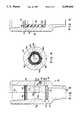
- FIG. 3 is a longitudinal cross-sectional view of the drill stem sub portion of the safety sub in accordance with a preferred embodiment of the invention, showing the elastomeric cross-section in open view.
- FIG. 4 is a lateral cross-sectional view taken at line 4--4 shown in FIG. 3.
- FIG. 5 is a longitudinal cross-sectional view of a portion of the entire safety sub shown in FIG. 3.
- FIG. 5A is a longitudinal cross-sectional view of a portion of the entire safety sub of an alternate embodiment including an elastomeric cartridge having an hour-glass shaped central bore.
- FIG. 6 is a side view of a preferred embodiment of the elastomeric cartridge portion of the safety sub shown in FIG. 3, disclosing the shape of the metallic end inserts and the elastomeric closure.
- FIG. 7 is a cross-sectional view of an alternate embodiment of an elastomeric cartridge in accordance with the present invention.
- FIG. 1 a typical drilling rig 10 is shown.
- the important operating components for understanding the operation of the present invention include drill pipe or drill string 12, which is made up of multiple joints of pipe connected end to end, the length of each joint typically being about 30 feet.
- the drill string supports bit 14 at its lower end and is hollow so that drilling fluid can be circulated down through the drill string to lubricate the cutting surfaces of the bit and to provide flushing or removal of cuttings and other debris up the annulus around the pipe.
- the effluent from the annulus is through flow nipple 16 to mud circulation system 18.
- a reservoir 20 of the drilling fluid permits settling of the foreign matter from the fluid and treatment of the fluid with suitable additives.
- a suction pipe 22 leading from the reservoir permits suitable pumping of the fluid up through stand pipe 24 and rotary hose 26 to a location above the kelly or drill stem 28, an elongated hexagonal or octagonal pipe that leads down through the central opening in rotary table 30.
- Rotary table 30 closes on the kelly and is rotated to produce the turning or rotating forces on the drill string to cause drilling.
- a safety sub 32 in accordance with the present invention is included in the drill string between the upper joint of drill pipe and the kelly.
- the circulation system is stopped, the string is raised so that the lower end of the kelly and the safety sub to be described more fully hereinafter are positioned just above the rotary table to permit disconnection of the string from the safety sub.
- the safety sub closes to prevent the fluid present in the kelly and the rotary hose and other components of the fluid circulation system located above the drill string from spilling or dumping out and not only making an environmental mess, but causing an unpleasant, slippery, possibly hazardous, and wasteful condition.
- the safety sub opens until the next time that fluid pressure in the drill string again is reduced.
- FIG. 2 a closer view of the operation just described is illustrated.
- the bottom of kelly 28 is connected to the top end of safety sub 32.
- a manually controlled drill stem ball valve sub 33 or the strippable kelly cock is connected to the lower end of sub 32 for positively shutting off the fluid when there is a requirement to have independent control of this function and not merely rely on the automatic shut-off associated with the safety sub alone.
- the ball valve sub is connected into the box end of the upper drill pipe of drill string 12. In any particular rig, there may be additional subs or a variation from what has been shown.
- the drilling rig illustrated in FIG. 1 is a rotary drilling rig that includes a kelly and a rotary table. Many drilling rigs do not include these components. Instead, such rigs include a so-called top drive power swivel.
- the safety sub described herein can be employed in such a rig by being connected directly to the power swivel in the same manner as it is connected to the kelly in FIG. 1.
- Safety sub 32 shown in FIG. 3 includes an outer drill stem sub section 34 and an internal elastomeric cartridge 36.
- Sub section 34 is externally threaded at its lower end for connection to the top joint of the drill string and includes a central bore 38, which is sized to be consistent or approximately the same as the central bore of the drill string.
- Central bore 40 in the middle of sub section 34 is enlarged with respect to bore 38, thereby forming an internal lip or ledge 42 for limiting the downward movement of cartridge 36.
- An internal groove in central bore 40 receives a snap ring 44 for retaining cartridge 36 in central bore 40.
- the bore is internally threaded for connection to the kelly, as previously described.
- elastomeric cartridge is comprised of a molded central closure section 46, an upper metallic end piece 48 and a lower metallic end piece 50. These metallic end pieces are each peripherally grooved to receive an 0-ring 52 and 54, respectively, for sealing against the inside surface of central bore 40.
- the molded central closure portion 46 of cartridge 36 includes three external depressions at evenly spaced positions around the periphery of closure portion 46. Depressions 56a and 56b are shown in FIG. 3 with the third depression, depression 56c being shown from the top sectional view illustrated in FIG. 4.
- the sidewall of sub section 34 includes an external recess 58 for receiving in a fixed location, such as by a threaded connection, charge valve 60.
- the recess is deep enough so that no part of the valve is beyond the external surface of sub section 34.
- the valve is positioned at a convenient access angle to the longitudinal axis of the sub section and its exit end is open to central bore 40, preferably opposite one of depressions 56a, 56b, and 56c. In FIG. 3, for convenience of illustration, valve 60 is shown slightly offset from depression 56b.
- the external surface of the elastomeric cartridge is pre-charged to an amount sufficient to cause the cartridge to seal off the bore without the circulation pressure having been cut off. Ordinarily, this pre-charge is about 450 psi.
- a valve suitable for performing in the manner described is a Schrader loading valve or its equivalent. Enough leakage communication exists around central closure 46 between O-ring seals 52 and 54 that there is equal inwardly directed radial pressure applied at each depression 56a, 56b and 56c.
- rods 62a, 62b and 62c are parallel to axis 64 and are spaced evenly around the cartridge so as to be located intermediate depressions 56a, 56b and 56c. They are also at a common radial distance from axis 64 to permit the elastomeric material to uniformly surround and bond to the rods during the molding process. It will be seen from FIG. 4 that the wall thickness of closure section 36 is considerably thicker in the areas supported by the rods than where the depressions are located.
- central closure 46 is cupped in a tapered conical fashion to receive the frustoconical ends of metallic end pieces 48 and 50.
- the taper angle is most conveniently at a catenary angle because, as with the rods previously discussed, the elastomeric material bonds to the metallic end inserts during the molding process.
- the catenary angle minimizes the amount of stress in the elastomeric material with respect to the bond of the elastomeric material to the metallic pieces as it flexes during closing and opening.
- FIG. 6 A preferred embodiment of the cartridge is shown in FIG. 6, where it can be seen that in addition to being a tapered conical surface, the insertion end of the metallic inserts includes an interlocking shape 66 to maximize the bonding.
- rods 62a, 62b and 62c are round to minimize the stresses in the elastomeric material that bonds to them.
- alternate rod shapes can be used, such as trapezoidal rods 68 shown in the alternate cartridge elastomeric closure appearing in FIG. 7.
- rods such as these that are elongated in cross section are used, the long sides thereof are aligned to be parallel to the radially closest tangents of the central bore opening of the closure structure since alignment of this nature permits proper flexing of the elastomer during closing and opening operations.
- the rods themselves can be either metallic or plastic and can also be somewhat flexible, as desired.
- the elastomeric material performs the entire closing and opening operation by its elastomeric properties alone and without movement of an end to the cartridge.
- the material that is employed possesses high elongation properties, has high tensile strength with the ability to rapidly dissipate energy, is highly resistant to flexure fatigue, and has a sufficiently high modulus to provide dimensional stability to the structure.
- a material that has been found having these qualities and is acceptable for the purpose described is a nitrile rubber.
- Other important characteristics that are desirable for the elastomeric material include resistance to oil and water contamination or degradation and to the other ingredients found in drilling fluids and retention of its desirable mechanical properties set forth above over a broad range of operating temperatures.
- An elastomer for the application described herein is characterized more specifically by these properties: hardness in Shore A units, 60-90; modulus, 1100-2700 si; ultimate elongation, 300-700%; and tensile set, 5-13%.
- the central bore of the elastomeric cartridge can be cylindrical. However, it has been found that there is an advantage to the internal bore 45 being slightly hour-glass shaped as shown in FIG. 5A to minimize the stresses in the rubber as the cusps flex to and from their respective closed positions.
- central closure 46 relaxes and provides a fully opened bore therethrough for accommodating a survey tool or the like.
- multiple longitudinal grooves can be molded in either the internal or external surface or both of molded central closure section 46 of the elastomeric cartridge to assist closure and sealing control and efficiency and to reduce the amount of closure force required for operation.
Landscapes
- Engineering & Computer Science (AREA)
- Life Sciences & Earth Sciences (AREA)
- Geology (AREA)
- Mining & Mineral Resources (AREA)
- Physics & Mathematics (AREA)
- Environmental & Geological Engineering (AREA)
- Fluid Mechanics (AREA)
- General Life Sciences & Earth Sciences (AREA)
- Geochemistry & Mineralogy (AREA)
- Mechanical Engineering (AREA)
- General Engineering & Computer Science (AREA)
- Earth Drilling (AREA)
Abstract
Description
Claims (26)
Priority Applications (1)
| Application Number | Priority Date | Filing Date | Title |
|---|---|---|---|
| US08/094,513 US5339864A (en) | 1993-07-20 | 1993-07-20 | Safety sub for retaining drilling fluids |
Applications Claiming Priority (1)
| Application Number | Priority Date | Filing Date | Title |
|---|---|---|---|
| US08/094,513 US5339864A (en) | 1993-07-20 | 1993-07-20 | Safety sub for retaining drilling fluids |
Publications (1)
| Publication Number | Publication Date |
|---|---|
| US5339864A true US5339864A (en) | 1994-08-23 |
Family
ID=22245610
Family Applications (1)
| Application Number | Title | Priority Date | Filing Date |
|---|---|---|---|
| US08/094,513 Expired - Lifetime US5339864A (en) | 1993-07-20 | 1993-07-20 | Safety sub for retaining drilling fluids |
Country Status (1)
| Country | Link |
|---|---|
| US (1) | US5339864A (en) |
Cited By (6)
| Publication number | Priority date | Publication date | Assignee | Title |
|---|---|---|---|---|
| GB2287494A (en) * | 1994-03-15 | 1995-09-20 | Hydril Co | Safety sub with asymmetrical wall elastomeric closure for retaining drilling fluids |
| US6053191A (en) * | 1997-02-13 | 2000-04-25 | Hussey; James J. | Mud-saver valve |
| US20050081918A1 (en) * | 2003-10-21 | 2005-04-21 | Seneviratne Padmasiri D. | Internal blow out preventer ball and seat |
| US20050167157A1 (en) * | 2003-12-31 | 2005-08-04 | George Boyadjieff | Instrumented internal blowout preventer valve for measuring drill string drilling parameters |
| US20060191679A1 (en) * | 2003-10-21 | 2006-08-31 | Seneviratne Padmasiri D | Triple valve blow out preventer |
| US20150267822A1 (en) * | 2014-03-18 | 2015-09-24 | Mine Support Products (Pty) Ltd | Valve |
Citations (5)
| Publication number | Priority date | Publication date | Assignee | Title |
|---|---|---|---|---|
| US3342215A (en) * | 1965-05-06 | 1967-09-19 | Bass Brothers Entpr Inc | Mud throttling valve |
| US3365009A (en) * | 1966-07-12 | 1968-01-23 | Gerald E. Burnham | Drilling fluid circulation system having flow parameter regulating means |
| US3955594A (en) * | 1974-02-25 | 1976-05-11 | Raymond International Inc. | Pressure operated valve systems |
| US4811758A (en) * | 1988-06-14 | 1989-03-14 | Torus Equipment, Inc. | Pressurized check valve |
| US5205325A (en) * | 1991-11-12 | 1993-04-27 | Piper Oilfield Products, Inc. | Flow control valve |
-
1993
- 1993-07-20 US US08/094,513 patent/US5339864A/en not_active Expired - Lifetime
Patent Citations (5)
| Publication number | Priority date | Publication date | Assignee | Title |
|---|---|---|---|---|
| US3342215A (en) * | 1965-05-06 | 1967-09-19 | Bass Brothers Entpr Inc | Mud throttling valve |
| US3365009A (en) * | 1966-07-12 | 1968-01-23 | Gerald E. Burnham | Drilling fluid circulation system having flow parameter regulating means |
| US3955594A (en) * | 1974-02-25 | 1976-05-11 | Raymond International Inc. | Pressure operated valve systems |
| US4811758A (en) * | 1988-06-14 | 1989-03-14 | Torus Equipment, Inc. | Pressurized check valve |
| US5205325A (en) * | 1991-11-12 | 1993-04-27 | Piper Oilfield Products, Inc. | Flow control valve |
Non-Patent Citations (4)
| Title |
|---|
| National Oilwell PS & PS2 500/500 Power Swivel, Kick Down Hole Pressure Control, Document No. 05 05 00, Undated. * |
| National Oilwell PS 500/500 & PS2 500/500 Power Swivel, Internal Blowout Preventer (IBOP) Assembly, Document No. 10 40 03, Undated. * |
| National-Oilwell PS & PS2-500/500 Power Swivel, "Kick" Down Hole Pressure Control, Document No. 05-05-00, Undated. |
| National-Oilwell PS 500/500 & PS2 500/500 Power Swivel, Internal Blowout Preventer (IBOP) Assembly, Document No. 10-40-03, Undated. |
Cited By (11)
| Publication number | Priority date | Publication date | Assignee | Title |
|---|---|---|---|---|
| GB2287494A (en) * | 1994-03-15 | 1995-09-20 | Hydril Co | Safety sub with asymmetrical wall elastomeric closure for retaining drilling fluids |
| GB2287494B (en) * | 1994-03-15 | 1997-08-06 | Hydril Co | Elastmeric cartridge subassembly for retaining drilling fluids |
| DE19509162C2 (en) * | 1994-03-15 | 2000-11-30 | Hydril Co | Splash guard with asymmetric elastomeric closure element |
| US6053191A (en) * | 1997-02-13 | 2000-04-25 | Hussey; James J. | Mud-saver valve |
| US20050081918A1 (en) * | 2003-10-21 | 2005-04-21 | Seneviratne Padmasiri D. | Internal blow out preventer ball and seat |
| US20060191679A1 (en) * | 2003-10-21 | 2006-08-31 | Seneviratne Padmasiri D | Triple valve blow out preventer |
| US7121295B2 (en) | 2003-10-21 | 2006-10-17 | Varco I/P, Inc. | Internal blow out preventer ball and seat |
| US7287544B2 (en) | 2003-10-21 | 2007-10-30 | Varco I/P, Inc. | Triple valve blow out preventer |
| US20050167157A1 (en) * | 2003-12-31 | 2005-08-04 | George Boyadjieff | Instrumented internal blowout preventer valve for measuring drill string drilling parameters |
| US7108081B2 (en) | 2003-12-31 | 2006-09-19 | Varco I/P, Inc. | Instrumented internal blowout preventer valve for measuring drill string drilling parameters |
| US20150267822A1 (en) * | 2014-03-18 | 2015-09-24 | Mine Support Products (Pty) Ltd | Valve |
Similar Documents
| Publication | Publication Date | Title |
|---|---|---|
| US4811758A (en) | Pressurized check valve | |
| US7779903B2 (en) | Solid rubber packer for a rotating control device | |
| US7380590B2 (en) | Rotating pressure control head | |
| EP0986690B1 (en) | Valve for use in a wellbore | |
| US7380610B2 (en) | Stripper rubber insert assembly | |
| US4281724A (en) | Drilling head | |
| US7240727B2 (en) | Armored stripper rubber | |
| US4151875A (en) | EZ disposal packer | |
| US6848471B2 (en) | In-line check valve | |
| US5435386A (en) | Cementing plug | |
| US4303100A (en) | Kelly valve | |
| NO313563B1 (en) | Inflatable liner packing and method of using the liner packing in a lined borehole | |
| US5873414A (en) | Bypass valve for downhole motor | |
| US5339864A (en) | Safety sub for retaining drilling fluids | |
| US5199494A (en) | Safety valve, sealing ring and seal assembly | |
| US4969513A (en) | High pressure automatic kelly valve | |
| US3703213A (en) | Mud saver apparatus | |
| US5364064A (en) | Safety sub with asymmetrical wall elastomeric closure for retaining drilling fluids | |
| US6910531B2 (en) | Rotating drilling stripper | |
| US3581834A (en) | Telescopic drill string unit | |
| US5782298A (en) | Retrievable safety packer | |
| WO2017066324A1 (en) | Pilot inside a ball suitable for wellbore operations | |
| US20190360303A1 (en) | Rolling seal for transfer of pressure in a downhole tool | |
| EP3362638A1 (en) | Pilot inside a ball suitable for wellbore operations |
Legal Events
| Date | Code | Title | Description |
|---|---|---|---|
| AS | Assignment |
Owner name: HYDRIL COMPANY, TEXAS Free format text: ASSIGNMENT OF ASSIGNORS INTEREST;ASSIGNORS:CARBAUGH, WILLIAM L.;CARLSON, DOUGLAS W.;REEL/FRAME:006641/0047 Effective date: 19930716 |
|
| FEPP | Fee payment procedure |
Free format text: PAYOR NUMBER ASSIGNED (ORIGINAL EVENT CODE: ASPN); ENTITY STATUS OF PATENT OWNER: LARGE ENTITY |
|
| FPAY | Fee payment |
Year of fee payment: 4 |
|
| AS | Assignment |
Owner name: CHASE BANK OF TEXAS, NATIONAL ASSOC., AS AGENT, TE Free format text: SECURITY INTEREST;ASSIGNOR:HYDRIL COMPANY;REEL/FRAME:009123/0016 Effective date: 19980323 |
|
| STPP | Information on status: patent application and granting procedure in general |
Free format text: APPLICATION UNDERGOING PREEXAM PROCESSING |
|
| FPAY | Fee payment |
Year of fee payment: 8 |
|
| REMI | Maintenance fee reminder mailed | ||
| AS | Assignment |
Owner name: HYDRIL COMPANY LP, TEXAS Free format text: ASSIGNMENT OF ASSIGNORS INTEREST;ASSIGNOR:HYDRIL COMPANY;REEL/FRAME:014499/0197 Effective date: 20020101 |
|
| AS | Assignment |
Owner name: HYDRIL COMPANY LP, TEXAS Free format text: ASSIGNMENT OF ASSIGNORS INTEREST;ASSIGNOR:HYDRIL COMPANY;REEL/FRAME:014763/0830 Effective date: 20030922 |
|
| AS | Assignment |
Owner name: HYDRIL COMPANY, TEXAS Free format text: RELEASE OF LIEN;ASSIGNOR:CHASE BANK OF TEXAS, NATIONAL ASSOCIATION;REEL/FRAME:014734/0860 Effective date: 20040604 |
|
| FPAY | Fee payment |
Year of fee payment: 12 |
|
| AS | Assignment |
Owner name: HYDRIL GENERAL LLC, TEXAS Free format text: MERGER;ASSIGNOR:HYDRIL COMPANY LP;REEL/FRAME:020718/0733 Effective date: 20070629 Owner name: HYDRIL LLC, TEXAS Free format text: CHANGE OF NAME;ASSIGNOR:HYDRIL GENERAL LLC;REEL/FRAME:020718/0758 Effective date: 20070719 Owner name: HYDRIL GENERAL LLC,TEXAS Free format text: MERGER;ASSIGNOR:HYDRIL COMPANY LP;REEL/FRAME:020718/0733 Effective date: 20070629 Owner name: HYDRIL LLC,TEXAS Free format text: CHANGE OF NAME;ASSIGNOR:HYDRIL GENERAL LLC;REEL/FRAME:020718/0758 Effective date: 20070719 |
|
| AS | Assignment |
Owner name: HYDRIL USA MANUFACTURING LLC, TEXAS Free format text: ASSIGNMENT OF ASSIGNORS INTEREST;ASSIGNOR:HYDRIL LLC;REEL/FRAME:021050/0491 Effective date: 20080401 Owner name: HYDRIL USA MANUFACTURING LLC,TEXAS Free format text: ASSIGNMENT OF ASSIGNORS INTEREST;ASSIGNOR:HYDRIL LLC;REEL/FRAME:021050/0491 Effective date: 20080401 |