US5325579A - Method of making window assembly - Google Patents
Method of making window assembly Download PDFInfo
- Publication number
- US5325579A US5325579A US07/877,717 US87771792A US5325579A US 5325579 A US5325579 A US 5325579A US 87771792 A US87771792 A US 87771792A US 5325579 A US5325579 A US 5325579A
- Authority
- US
- United States
- Prior art keywords
- window
- stile
- frame members
- window assembly
- rail
- Prior art date
- Legal status (The legal status is an assumption and is not a legal conclusion. Google has not performed a legal analysis and makes no representation as to the accuracy of the status listed.)
- Expired - Lifetime
Links
- 238000004519 manufacturing process Methods 0.000 title claims description 10
- 230000014759 maintenance of location Effects 0.000 claims abstract description 17
- 239000002023 wood Substances 0.000 claims description 4
- 230000000712 assembly Effects 0.000 claims description 2
- 238000000429 assembly Methods 0.000 claims description 2
- 238000000034 method Methods 0.000 claims 4
- 239000003570 air Substances 0.000 claims 2
- 239000012080 ambient air Substances 0.000 claims 1
- 239000011521 glass Substances 0.000 abstract description 14
- BQCADISMDOOEFD-UHFFFAOYSA-N Silver Chemical compound [Ag] BQCADISMDOOEFD-UHFFFAOYSA-N 0.000 abstract description 9
- 230000005540 biological transmission Effects 0.000 abstract description 5
- 229920006267 polyester film Polymers 0.000 abstract description 4
- 229910052709 silver Inorganic materials 0.000 abstract description 4
- 239000004332 silver Substances 0.000 abstract description 4
- 238000002834 transmittance Methods 0.000 abstract description 4
- 238000005553 drilling Methods 0.000 abstract description 3
- 229910052743 krypton Inorganic materials 0.000 abstract description 3
- DNNSSWSSYDEUBZ-UHFFFAOYSA-N krypton atom Chemical compound [Kr] DNNSSWSSYDEUBZ-UHFFFAOYSA-N 0.000 abstract description 3
- 238000010276 construction Methods 0.000 description 8
- 238000000576 coating method Methods 0.000 description 7
- 239000010410 layer Substances 0.000 description 7
- 239000011248 coating agent Substances 0.000 description 6
- 238000001914 filtration Methods 0.000 description 5
- 238000005253 cladding Methods 0.000 description 3
- 238000005516 engineering process Methods 0.000 description 3
- XLOMVQKBTHCTTD-UHFFFAOYSA-N Zinc monoxide Chemical compound [Zn]=O XLOMVQKBTHCTTD-UHFFFAOYSA-N 0.000 description 2
- 230000008901 benefit Effects 0.000 description 2
- 238000005562 fading Methods 0.000 description 2
- 229910052751 metal Inorganic materials 0.000 description 2
- 239000002184 metal Substances 0.000 description 2
- XOLBLPGZBRYERU-UHFFFAOYSA-N tin dioxide Chemical compound O=[Sn]=O XOLBLPGZBRYERU-UHFFFAOYSA-N 0.000 description 2
- 229910001887 tin oxide Inorganic materials 0.000 description 2
- 241000479842 Pella Species 0.000 description 1
- 238000009833 condensation Methods 0.000 description 1
- 230000005494 condensation Effects 0.000 description 1
- 230000007613 environmental effect Effects 0.000 description 1
- 239000004744 fabric Substances 0.000 description 1
- 229920001903 high density polyethylene Polymers 0.000 description 1
- 239000000463 material Substances 0.000 description 1
- 230000004048 modification Effects 0.000 description 1
- 238000012986 modification Methods 0.000 description 1
- 229920003023 plastic Polymers 0.000 description 1
- 239000002356 single layer Substances 0.000 description 1
- 125000006850 spacer group Chemical group 0.000 description 1
- 239000011787 zinc oxide Substances 0.000 description 1
Images


Classifications
-
- E—FIXED CONSTRUCTIONS
- E06—DOORS, WINDOWS, SHUTTERS, OR ROLLER BLINDS IN GENERAL; LADDERS
- E06B—FIXED OR MOVABLE CLOSURES FOR OPENINGS IN BUILDINGS, VEHICLES, FENCES OR LIKE ENCLOSURES IN GENERAL, e.g. DOORS, WINDOWS, BLINDS, GATES
- E06B7/00—Special arrangements or measures in connection with doors or windows
- E06B7/12—Measures preventing the formation of condensed water
-
- E—FIXED CONSTRUCTIONS
- E06—DOORS, WINDOWS, SHUTTERS, OR ROLLER BLINDS IN GENERAL; LADDERS
- E06B—FIXED OR MOVABLE CLOSURES FOR OPENINGS IN BUILDINGS, VEHICLES, FENCES OR LIKE ENCLOSURES IN GENERAL, e.g. DOORS, WINDOWS, BLINDS, GATES
- E06B3/00—Window sashes, door leaves, or like elements for closing wall or like openings; Layout of fixed or moving closures, e.g. windows in wall or like openings; Features of rigidly-mounted outer frames relating to the mounting of wing frames
- E06B3/66—Units comprising two or more parallel glass or like panes permanently secured together
- E06B3/677—Evacuating or filling the gap between the panes ; Equilibration of inside and outside pressure; Preventing condensation in the gap between the panes; Cleaning the gap between the panes
-
- Y—GENERAL TAGGING OF NEW TECHNOLOGICAL DEVELOPMENTS; GENERAL TAGGING OF CROSS-SECTIONAL TECHNOLOGIES SPANNING OVER SEVERAL SECTIONS OF THE IPC; TECHNICAL SUBJECTS COVERED BY FORMER USPC CROSS-REFERENCE ART COLLECTIONS [XRACs] AND DIGESTS
- Y10—TECHNICAL SUBJECTS COVERED BY FORMER USPC
- Y10T—TECHNICAL SUBJECTS COVERED BY FORMER US CLASSIFICATION
- Y10T29/00—Metal working
- Y10T29/49—Method of mechanical manufacture
- Y10T29/49826—Assembling or joining
- Y10T29/49892—Joining plate edge perpendicularly to frame
Definitions
- This invention relates to an improved and simplified window frame construction that is less expensive to manufacture and allows for the use of optional accessories.
- a window assembly also includes a highly efficient energy filter system.
- FIGS. 19-21 The Rolscreen Company, Pella, Iowa, has marketed a window assembly as represented in FIGS. 19-21 which includes a fixed glazing panel 10 and a removable panel 12. Pivot retention clips 14 are carried on removable panel 12 and are received in notches 16 to hold the panel in place.
- a breather passageway 18 allows ambient outside air to communicate with the space between the glazing panels 10 and 12.
- the construction of this window requires separate manufacturing steps to form the breather passageway 18 and the notch 16 in the rail frame member 20 and the stile frame member 22.
- One of the objects of this invention is to simplify this manufacturing procedure so that frame components can be in part mass produced and customized as required with a minimum of manufacturing steps.
- the Rolscreen Company has made popular a window assembly having an adjustable blind positioned between the removable inside glazing panel and the outside fixed window unit. While this product has been very successful, it is desirable to have a variety of accessory options if they can be provided at a reasonable cost to manufacture.
- An objective of this invention thus is to provide a basic window frame construction which allows for final modification at the time of assembly for construction of any number of different accessorized window assemblies which may include multiple accessories between the glazing panels.
- an object of this invention is to uniquely combine certain features of different systems into one to maximize their benefits to the window consumer. It is an object to filter out the ultraviolet light that causes fading while maximizing the transmission of visible light and then again filtering out the near infrared and long wave light.
- Ultraviolet rays are from 0 to 390 nanometers while the visible region is 390 to 760 and near infrared is from 760 to 2,500.
- the long wave light is above 2,500.
- This invention has as an object to provide an energy control system that will filter out as much energy as possible at the top end of the ultraviolet region near its interface with the visible light. This would generally include wave length on the order of 360 to 380 nanometers. It is also an object to strike a balance between the objectives of minimizing near infrared transmission while maximizing visible light.
- This invention allows for the manufacture of an inventory of partially finished stile and rail frame members wherein a minimum of manufacturing steps are required at the time of final window assembly.
- Component frame members have been provided which due to their construction are suitable for use in a variety of different window models.
- One example is as an alternative to the individually formed notches 16 to receive the retention clips 14.
- a continuous groove is preformed in all of the stile and rail members which will accept the retention clips regardless of their location.
- a length of frame member may be cut off at any point without the need for forming a retention clip notch that will match up with the removable panel retention clip locations.
- This invention also eliminates the need for drilling breather passageways 18 as a final step in the construction of a window assembly.
- the end cut of the stile member includes a downwardly facing U-shaped passageway that functions as a breather opening and may be protected against moisture by being lined with a plastic sleeve insert. No separate drilling operation is required as the passageway is an integral part of the end cut operation.
- the common rail and stile frame members have a width such that they may be utilized with single glazing panels or multiple glazing panels with multiple window accessories such as blinds and muntin bars positioned between the fixed panel and the removable window unit.
- An upstanding wood stop and spacer extends around the perimeter of the window assembly and its width is determined by the needs of the particular window design that is desired and thus the final routing step will cut away the appropriate amount of material to accommodate the desired accessories and glazing panels.
- a grid of muntin bars may be removably attached to the inside face of the outside glazing panel while at the same time the space between the two glazing panels can accommodate an adjustable blind.
- an insulated glass unit having sealed double glazing panels can be incorporated into a window frame which will also accommodate a third glazing panel which is removable from the inside of the room.
- Low-E2 includes two layers of transparent silver metal on the inside face of the outer glazing panel. In between the two glazing panels of the sealed double glazing panel unit, a single layer of silver metal is provided on a stretched polyester film. This filter is known as Heat Mirror 88 (HM88) and it is distributed by Southwall Technologies, Palo Alto, Calif. A third glazing panel may be used which is removable on the inside of the room and may contain one layer of transparent tin oxide metal. If the insulated glass unit is filled with krypton gas the window assembly will have a center of glass rating of R8.9.
- HM88 Heat Mirror 88
- FIG. 1 is a fragmentary perspective view of a home having a window assembly of this invention.
- FIG. 2 is a fragmentary perspective view of a corner section of the window unit as indicated by the lines 2--2 in FIG. 1.
- FIG. 3 is a cross sectional view taken along line 3--3 in FIG. 2 and illustrates the continuous preformed retention clip groove and the end cut with breather opening.
- FIG. 4 is a cross sectional view taken along line 4--4 in FIG. 2.
- FIG. 5 is a view taken along line 5--5 in FIG. 4.
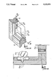
- FIG. 6 is an exploded corner sectional view.
- FIG. 7 is a fragmentary top plan view of the end of the rail member showing its end cut.
- FIG. 8 is a view taken along line 8--8 in FIG. 6 of only the lower end of a stile member showing the end cut.
- FIG. 9 is a perspective view of an assembled window assembly which includes an internal muntin bar grid along with an adjustable blind.
- FIG. 10 is a cross sectional view taken along line 10--10 in FIG. 9.
- FIG. 11 is a perspective view of a window assembly having a sealed double glazing window unit and a removable glazing panel with an adjustable blind therebetween.
- FIG. 12 is a cross sectional view taken along line 12--12 in FIG. 11.
- FIG. 13 is a fragmentary perspective view of a corner section illustrating the light and heat energy control systems incorporated into the window assembly.
- FIG. 14 is a cross sectional view taken along line 14--14 in FIG. 13 with the exterior cladding having been added.
- FIG. 15 is an enlarged cross sectional view generally of the transparent silver metal film as indicated by the line 15--15 in FIG. 14.
- FIG. 16 is a view similar to FIG. 15 but illustrating the cross sectional construction of the double silver metal layers on the interior face of the outer glazing panel in an insulated double glazing window unit as indicated by the line 16--16 in FIG. 14.
- FIG. 17 is a graphical representation of the energy transmittance control system of this invention as compared to two alternate systems.
- FIG. 18 is an enlarged graphical representation similar to FIG. 17 but of only the ultraviolet and visible regions of the graph.
- FIG. 18A is a graphical representation similar to that of FIG. 18 but with the ultraviolet 360-380 nanometer area, indicated by the line 18A--18A in FIG. 18, further enlarged.
- FIG. 19 is a fragmentary cross sectional view of a window assembly corner illustrating the prior art on which this invention is an improvement.
- FIG. 20 is a cross sectional view taken along line 20--20 in FIG. 19.
- FIG. 21 is an exploded fragmentary view of the stile and rail frame members of the prior art devices of FIGS. 19 and 20.
- the improved window assembly of this invention is referred to generally by the reference numeral 30 in FIG. 1 where a house 32 is represented.
- the window frame of this window assembly is illustrated in FIGS. 2-8 and includes a stile frame member 34 joined to a rail member 36. Each of these members are preformed for inventory in lengths that will be subsequently cut to length for a given window.
- Each of the stile and rail frame members 34 and 36 will include cladding grooves 38, 40 and 42 for attachment of cladding 44 as seen in FIGS. 10 and 12.
- a continuous V-shaped clip retention groove 46 is formed in the wood frame members and is provided with a plastic liner 48 to receive a pivotable retention clip 49 as seen in FIGS. 10 and 12.
- a glass stop 50 is provided intermediate the opposite sides of the frame members and its width will be cut to size depending on the requirements of a particular window assembly.
- the glass stop 50 in the stile frame member 34 will include a routed breather channel 52 which is formed at the same time the preassembled mortise end cut is made as seen in FIG. 8.
- the tenon end cut of the rail member 36 is seen in FIG. 7.
- a breather sleeve 54 is fitted into the channel 52 and rests upon the top face of the glass stop 50 of the rail member 36.
- FIGS. 9-12 alternative window constructions are seen possible utilizing the basic frame components which make up the rail frame members 36 shown.
- an exterior glazing panel 58 includes on its inside face 60 a muntin bar grid 62 and next to it is an adjustable blind 64.
- a removable interior glazing panel 66 is held in place by retractable retention clips 49 received in the continuous retention groove 46.
- the width of the glass stop 50 is cut to the appropriate size and varies as seen in the two embodiments of FIGS. 10 and 12.
- an insulated double pane panel 68 is substituted for the single glazing panel 58 and the blind 64 is positioned between the panel 68 and the removable panel 66.
- the energy filter control system of this invention is illustrated in FIGS. 13-16.
- the insulated double glazing panel 68 includes a pair of glass panes 70 and 72.
- the glazing 70 includes a coating 74 seen in FIG. 16. This coating is seen to include two transparent silver layers 76 and 78 with zinc oxide dielectric layers on the outside at 80, in between at 82 and next to the glass 70 at 84.
- This coating 74 is referred to by the Rolscreen Company as Low-E2 spoken as "low E squared". Glass with this coating on it is provided by Cardinal Glass, Minneapolis, Minn.
- a clear polyester film 86 Suspended between the glazing panes 70 and 72 is a clear polyester film 86 with a coating of silver 88 sandwiched between dialectic layers 90 and 92 as seen in FIG. 15.
- the inner glazing pane 72 of the sealed panel 68 is clear glass.
- the film 86 is sold by Southwall Technologies, Inc., Palo Alto, Calif., as Heat Mirror 88.
- the removable panel 66 preferably includes a Low-E coating which has one layer of transparent tin oxide metal. With the insulated panel 68 being filled with krypton the window assembly will carry an R8.9 rating.
- the combination system is approximately half way between the other two systems in the visible light region of 390-760. In the near infrared region the combination system is very close to the two Low-E2 system and is substantially better that the two HM88 system which allows considerably more energy transmittance. Accordingly, it is believed that the best features of several systems have been uniquely combined to provide a superior energy transmittance control system.
Landscapes
- Engineering & Computer Science (AREA)
- Civil Engineering (AREA)
- Structural Engineering (AREA)
- Securing Of Glass Panes Or The Like (AREA)
- Specific Sealing Or Ventilating Devices For Doors And Windows (AREA)
- Wing Frames And Configurations (AREA)
Abstract
Description
Claims (6)
Priority Applications (2)
| Application Number | Priority Date | Filing Date | Title |
|---|---|---|---|
| US07/877,717 US5325579A (en) | 1991-11-18 | 1992-05-04 | Method of making window assembly |
| CA 2093832 CA2093832C (en) | 1992-05-04 | 1993-04-13 | Window assembly and method of making same |
Applications Claiming Priority (2)
| Application Number | Priority Date | Filing Date | Title |
|---|---|---|---|
| US07/793,475 US5299399A (en) | 1991-11-18 | 1991-11-18 | Window panel with breather system |
| US07/877,717 US5325579A (en) | 1991-11-18 | 1992-05-04 | Method of making window assembly |
Related Parent Applications (1)
| Application Number | Title | Priority Date | Filing Date |
|---|---|---|---|
| US07/793,475 Continuation-In-Part US5299399A (en) | 1991-11-18 | 1991-11-18 | Window panel with breather system |
Publications (1)
| Publication Number | Publication Date |
|---|---|
| US5325579A true US5325579A (en) | 1994-07-05 |
Family
ID=25160006
Family Applications (2)
| Application Number | Title | Priority Date | Filing Date |
|---|---|---|---|
| US07/793,475 Expired - Lifetime US5299399A (en) | 1991-11-18 | 1991-11-18 | Window panel with breather system |
| US07/877,717 Expired - Lifetime US5325579A (en) | 1991-11-18 | 1992-05-04 | Method of making window assembly |
Family Applications Before (1)
| Application Number | Title | Priority Date | Filing Date |
|---|---|---|---|
| US07/793,475 Expired - Lifetime US5299399A (en) | 1991-11-18 | 1991-11-18 | Window panel with breather system |
Country Status (3)
| Country | Link |
|---|---|
| US (2) | US5299399A (en) |
| JP (1) | JPH05141153A (en) |
| CA (1) | CA2061747C (en) |
Cited By (32)
| Publication number | Priority date | Publication date | Assignee | Title |
|---|---|---|---|---|
| DE29506113U1 (en) * | 1995-04-07 | 1995-06-01 | Hampel Zoellner Ges Fuer Klass | Insulating glass window |
| US5619828A (en) * | 1994-12-19 | 1997-04-15 | Pella Corporation | Installation fin for windows and doors |
| WO1998028768A1 (en) * | 1996-12-23 | 1998-07-02 | Optical Coating Laboratory, Inc. | Methods and apparatus for providing an optically enhancing/noise suppressing device for plasma display panels |
| US6067188A (en) * | 1996-12-23 | 2000-05-23 | Optical Coating Laboratory, Inc. | Apparatus for providing a near-IR emission suppressing/color enhancing accessory device for plasma display panels |
| WO2000042270A1 (en) | 1999-01-14 | 2000-07-20 | Gieseke Gerald G | Muntin bar clip |
| US6393778B1 (en) * | 1997-07-03 | 2002-05-28 | Raymond M. L. Ting | Airloop window system |
| WO2002046547A2 (en) | 2000-10-19 | 2002-06-13 | Gieseke Gerald G | Muntin bar clip with spikes |
| US6591562B2 (en) | 2001-08-20 | 2003-07-15 | Raymond M. L. Ting | Apparatus for securing curtain wall supports |
| US6598361B2 (en) | 2001-08-20 | 2003-07-29 | Raymond M. L. Ting | Mullion splice joint design |
| US6606837B2 (en) | 2001-08-28 | 2003-08-19 | Cardinal Ig | Methods and devices for simultaneous application of end sealant and sash sealant |
| US6793971B2 (en) | 2001-12-03 | 2004-09-21 | Cardinal Ig Company | Methods and devices for manufacturing insulating glass units |
| US20040216402A1 (en) * | 2003-05-02 | 2004-11-04 | Peter Folsom | Muntin grid assembly and mounting system |
| US20060112654A1 (en) * | 2004-11-03 | 2006-06-01 | Gerhard Reichert | Muntin clip and method of using the same |
| US20060150561A1 (en) * | 2005-01-11 | 2006-07-13 | Pella Corporation | Window assembly with movable interior sash |
| US20060150514A1 (en) * | 2005-01-11 | 2006-07-13 | Pella Corporation | Movable light latch |
| US20060151129A1 (en) * | 2005-01-11 | 2006-07-13 | Pella Corporation | Window covering drive system |
| US20060169418A1 (en) * | 2002-07-22 | 2006-08-03 | Pella Corporation | Window covering leveling method |
| US20070169427A1 (en) * | 2006-01-24 | 2007-07-26 | Lee David E Iii | Decorative grid system and method |
| US20080163572A1 (en) * | 2006-01-24 | 2008-07-10 | David Eugene Lee | Decorative grid system and method |
| US20080263972A1 (en) * | 2004-03-05 | 2008-10-30 | Filippo Ramin | Energy-Saving Automatic Window Obtained by Using Solar Energy During the Cold Season, Control of Solar Radiation in Summer, Thermal Insulation, Controlled Internal Incidence of Light, Controlled Air Exchange |
| WO2012082288A1 (en) * | 2010-12-13 | 2012-06-21 | Southwall Technologies, Inc. | Insulating glass unit with crack-resistant low-emissivity suspended film |
| US20130098565A1 (en) * | 2010-06-08 | 2013-04-25 | Hunter Douglas Inc. | Unitary assembly for an architectural fenestration, providing dynamic solar heat gain control |
| US8555572B1 (en) | 2009-10-22 | 2013-10-15 | Glenn Bingham | Storm window assembly and methods of use |
| US8728636B2 (en) | 2010-12-13 | 2014-05-20 | Southwall Technologies Inc. | Insulating glass unit with crack-resistant low-emissivity suspended film |
| US9103156B1 (en) * | 2008-11-25 | 2015-08-11 | Anton Koytchev Vassilev | Attachable built-in blinds for doors and windows |
| US9109812B2 (en) | 2008-08-25 | 2015-08-18 | Hunter Douglas Inc. | Solar heating cells and support apparatus therefor |
| US9366080B2 (en) | 2008-11-18 | 2016-06-14 | Hunter Douglas Inc. | Slatted roller blind |
| US9458663B2 (en) | 2010-04-16 | 2016-10-04 | Hunter Douglas Inc. | Process and system for manufacturing a roller blind |
| US9540874B2 (en) | 2011-04-15 | 2017-01-10 | Hunter Douglas Inc. | Covering for architectural opening including cell structures biased to open |
| US9702186B2 (en) | 2005-03-16 | 2017-07-11 | Hunter Douglas Inc. | Single-Track stacking panel covering for an architectural opening |
| US10648229B2 (en) | 2016-06-30 | 2020-05-12 | Hunter Douglas Inc. | Architectural covering and method of manufacturing |
| US11964897B2 (en) | 2020-08-31 | 2024-04-23 | The Cooper Group, Llc | Historically accurate simulated divided light glass unit and methods of making the same |
Families Citing this family (19)
| Publication number | Priority date | Publication date | Assignee | Title |
|---|---|---|---|---|
| FR2778203B1 (en) | 1998-04-29 | 2000-06-09 | Lapeyre | BREATHABLE MULTIPLE GLAZING |
| US6397662B1 (en) | 2000-02-16 | 2002-06-04 | Can-Best Building Sciences Corporation | Gas concentration meter and insulating glass assembly and method thereof |
| US6916392B2 (en) | 2001-06-21 | 2005-07-12 | Cardinal Ig Company | Producing and servicing insulating glass units |
| US6804924B2 (en) * | 2001-10-12 | 2004-10-19 | Cardinal Ig Company | Repair of insulating glass units |
| FR2840011B1 (en) * | 2002-05-27 | 2008-04-18 | Maine Plastiques | BREATHABLE DOUBLE-WINDOW WINDOW |
| US7607267B2 (en) * | 2002-10-04 | 2009-10-27 | Bovard Studio, Inc | Apparatus for venting of protective panels |
| GB2421977B (en) * | 2003-09-26 | 2007-07-18 | David Howard Ambrose | System for elleviating in-vault condensation in double-glazed windows |
| US8112860B2 (en) * | 2003-12-17 | 2012-02-14 | Stephen Collins | Method of treating glazing panels |
| US7490441B2 (en) * | 2005-10-14 | 2009-02-17 | Pella Corporation | High performance window and door installation |
| US20070199259A1 (en) * | 2006-02-24 | 2007-08-30 | Parsley Andrew J | Secondary window with vacuum valve and alarm |
| US8006445B2 (en) | 2006-06-29 | 2011-08-30 | Pella Corporation | Self-sealing window installation and method |
| US20080127564A1 (en) * | 2006-06-29 | 2008-06-05 | Pella Corporation | Pre-hung door assembly and method of installation |
| KR101238125B1 (en) * | 2007-12-29 | 2013-02-27 | (주)엘지하우시스 | Dual doors having ventilation function |
| US8833035B2 (en) | 2011-01-26 | 2014-09-16 | Pella Corporation | Fenestration unit replacement method and system |
| WO2016191669A1 (en) | 2015-05-27 | 2016-12-01 | Pella Corporation | Water management systems for fenestration products |
| CA3031347A1 (en) | 2016-07-29 | 2018-02-01 | Masonite Corporation | Door assemblies with insulated glazing unit venting |
| US10227817B2 (en) * | 2017-05-08 | 2019-03-12 | Advanced Building Systems, Inc. | Vented insulated glass unit |
| JP7018612B2 (en) * | 2018-04-13 | 2022-02-14 | Ykk Ap株式会社 | Illuminance adjustment window |
| US11332946B2 (en) | 2018-07-25 | 2022-05-17 | Pella Corporation | Installation features for fenestration units and associated methods |
Citations (7)
| Publication number | Priority date | Publication date | Assignee | Title |
|---|---|---|---|---|
| FR1267007A (en) * | 1959-09-11 | 1961-07-17 | Window | |
| US3389737A (en) * | 1965-12-07 | 1968-06-25 | Rolscreen Co | Venetian blind for double glazed sash |
| US3562972A (en) * | 1969-04-17 | 1971-02-16 | Cyrus D Amato | Greenhouse construction |
| US4274469A (en) * | 1978-10-30 | 1981-06-23 | Rolscreen Company | Operator for a slat shade assembly |
| US4627206A (en) * | 1985-09-12 | 1986-12-09 | Rollscreen Company | Window sash breather device |
| US4913213A (en) * | 1987-12-21 | 1990-04-03 | Rolscreen Company | Pleted blind between window panes |
| US5226466A (en) * | 1989-02-16 | 1993-07-13 | Coddens Dean A | Window assembly including adjustable blind |
Family Cites Families (6)
| Publication number | Priority date | Publication date | Assignee | Title |
|---|---|---|---|---|
| US462652A (en) * | 1891-11-03 | Ventilator | ||
| US2159661A (en) * | 1938-03-01 | 1939-05-23 | Pittsburgh Plate Glass Co | Double glazed window |
| US2264176A (en) * | 1940-02-06 | 1941-11-25 | Pittsburgh Plate Glass Co | Multiple glazed unit |
| JPS57160891A (en) * | 1981-03-27 | 1982-10-04 | Mitsubishi Heavy Ind Ltd | Guyless derrick device |
| FI73044C (en) * | 1983-11-09 | 1988-05-17 | Partek Ab | Window. |
| US4656803A (en) * | 1986-06-09 | 1987-04-14 | Chludil Steven T | Multiply glazed window and door assemblies with screened breathing passages |
-
1991
- 1991-11-18 US US07/793,475 patent/US5299399A/en not_active Expired - Lifetime
-
1992
- 1992-02-24 CA CA002061747A patent/CA2061747C/en not_active Expired - Fee Related
- 1992-03-06 JP JP4082933A patent/JPH05141153A/en active Pending
- 1992-05-04 US US07/877,717 patent/US5325579A/en not_active Expired - Lifetime
Patent Citations (7)
| Publication number | Priority date | Publication date | Assignee | Title |
|---|---|---|---|---|
| FR1267007A (en) * | 1959-09-11 | 1961-07-17 | Window | |
| US3389737A (en) * | 1965-12-07 | 1968-06-25 | Rolscreen Co | Venetian blind for double glazed sash |
| US3562972A (en) * | 1969-04-17 | 1971-02-16 | Cyrus D Amato | Greenhouse construction |
| US4274469A (en) * | 1978-10-30 | 1981-06-23 | Rolscreen Company | Operator for a slat shade assembly |
| US4627206A (en) * | 1985-09-12 | 1986-12-09 | Rollscreen Company | Window sash breather device |
| US4913213A (en) * | 1987-12-21 | 1990-04-03 | Rolscreen Company | Pleted blind between window panes |
| US5226466A (en) * | 1989-02-16 | 1993-07-13 | Coddens Dean A | Window assembly including adjustable blind |
Non-Patent Citations (4)
| Title |
|---|
| "Southwall Introduces First Commercial R-8 Superwindow" in International Solar Energy Intelligence Report on Dec. 29, 1989 p. 259. |
| By Barnaby Feder "Smart Windows, Intriguing Potential" in The New York Times on Sunday, Apr. 8, 1990, pp. 1-2 Business Section. |
| By Barnaby Feder Smart Windows, Intriguing Potential in The New York Times on Sunday, Apr. 8, 1990, pp. 1 2 Business Section. * |
| Southwall Introduces First Commercial R 8 Superwindow in International Solar Energy Intelligence Report on Dec. 29, 1989 p. 259. * |
Cited By (57)
| Publication number | Priority date | Publication date | Assignee | Title |
|---|---|---|---|---|
| US5619828A (en) * | 1994-12-19 | 1997-04-15 | Pella Corporation | Installation fin for windows and doors |
| DE29506113U1 (en) * | 1995-04-07 | 1995-06-01 | Hampel Zoellner Ges Fuer Klass | Insulating glass window |
| WO1998028768A1 (en) * | 1996-12-23 | 1998-07-02 | Optical Coating Laboratory, Inc. | Methods and apparatus for providing an optically enhancing/noise suppressing device for plasma display panels |
| US5811923A (en) * | 1996-12-23 | 1998-09-22 | Optical Coating Laboratory, Inc. | Plasma display panel with infrared absorbing coating |
| US6067188A (en) * | 1996-12-23 | 2000-05-23 | Optical Coating Laboratory, Inc. | Apparatus for providing a near-IR emission suppressing/color enhancing accessory device for plasma display panels |
| US6084705A (en) * | 1996-12-23 | 2000-07-04 | Optical Coating Laboratory, Inc. | Methods and apparatus for providing a near-IR emission suppressing/color enhancing accessory device for plasma display panels |
| US20030041538A1 (en) * | 1997-07-03 | 2003-03-06 | Ting Raymond M. L. | Enhanced curtain wall system |
| US6393778B1 (en) * | 1997-07-03 | 2002-05-28 | Raymond M. L. Ting | Airloop window system |
| US7134247B2 (en) | 1997-07-03 | 2006-11-14 | Advanced Building Systems, Inc. | Enhanced curtain wall system |
| WO2000042270A1 (en) | 1999-01-14 | 2000-07-20 | Gieseke Gerald G | Muntin bar clip |
| US6131356A (en) * | 1999-01-14 | 2000-10-17 | Gieseke; Gerald G. | Muntin bar clip |
| US6494002B1 (en) | 2000-10-19 | 2002-12-17 | Gerald G. Gieseke | Muntin bar clip with spikes |
| WO2002046547A2 (en) | 2000-10-19 | 2002-06-13 | Gieseke Gerald G | Muntin bar clip with spikes |
| US6591562B2 (en) | 2001-08-20 | 2003-07-15 | Raymond M. L. Ting | Apparatus for securing curtain wall supports |
| US6598361B2 (en) | 2001-08-20 | 2003-07-29 | Raymond M. L. Ting | Mullion splice joint design |
| US6606837B2 (en) | 2001-08-28 | 2003-08-19 | Cardinal Ig | Methods and devices for simultaneous application of end sealant and sash sealant |
| US20030226332A1 (en) * | 2001-08-28 | 2003-12-11 | Cardinal Ig | Methods and devices for simultaneous application of end sealant and sash sealant |
| US6793971B2 (en) | 2001-12-03 | 2004-09-21 | Cardinal Ig Company | Methods and devices for manufacturing insulating glass units |
| US20050013950A1 (en) * | 2001-12-03 | 2005-01-20 | Cardinal Ig Company | Methods and devices for manufacturing insulating glass units |
| US20060169418A1 (en) * | 2002-07-22 | 2006-08-03 | Pella Corporation | Window covering leveling method |
| US20040216402A1 (en) * | 2003-05-02 | 2004-11-04 | Peter Folsom | Muntin grid assembly and mounting system |
| US6898914B2 (en) | 2003-05-02 | 2005-05-31 | Peter Folsom | Muntin grid assembly and mounting system |
| US7681619B2 (en) * | 2004-03-05 | 2010-03-23 | Filippo Ramin | Energy-saving automatic window obtained by using solar energy during the cold season, control of solar radiation in summer, thermal insulation, controlled internal incidence of light, controlled air exchange |
| US20080263972A1 (en) * | 2004-03-05 | 2008-10-30 | Filippo Ramin | Energy-Saving Automatic Window Obtained by Using Solar Energy During the Cold Season, Control of Solar Radiation in Summer, Thermal Insulation, Controlled Internal Incidence of Light, Controlled Air Exchange |
| US20060112654A1 (en) * | 2004-11-03 | 2006-06-01 | Gerhard Reichert | Muntin clip and method of using the same |
| US7716885B2 (en) | 2004-11-03 | 2010-05-18 | Edgetech I.G., Inc. | Muntin clip and method of using the same |
| US20060151129A1 (en) * | 2005-01-11 | 2006-07-13 | Pella Corporation | Window covering drive system |
| US20060150514A1 (en) * | 2005-01-11 | 2006-07-13 | Pella Corporation | Movable light latch |
| US20060150561A1 (en) * | 2005-01-11 | 2006-07-13 | Pella Corporation | Window assembly with movable interior sash |
| US7765741B2 (en) | 2005-01-11 | 2010-08-03 | Pella Corporation | Movable light latch |
| US8376019B2 (en) | 2005-01-11 | 2013-02-19 | Pella Corporation | Window assembly with movable interior sash |
| US10689903B2 (en) | 2005-03-16 | 2020-06-23 | Hunter Douglas Inc. | Single-track stacking panel covering for an architectural opening |
| US9702186B2 (en) | 2005-03-16 | 2017-07-11 | Hunter Douglas Inc. | Single-Track stacking panel covering for an architectural opening |
| US20070169427A1 (en) * | 2006-01-24 | 2007-07-26 | Lee David E Iii | Decorative grid system and method |
| US20080163572A1 (en) * | 2006-01-24 | 2008-07-10 | David Eugene Lee | Decorative grid system and method |
| US9109812B2 (en) | 2008-08-25 | 2015-08-18 | Hunter Douglas Inc. | Solar heating cells and support apparatus therefor |
| US11299930B2 (en) | 2008-11-18 | 2022-04-12 | Hunter Douglas Inc. | Slatted roller blind |
| US9366080B2 (en) | 2008-11-18 | 2016-06-14 | Hunter Douglas Inc. | Slatted roller blind |
| US10145172B2 (en) | 2008-11-18 | 2018-12-04 | Hunter Douglas Inc. | Slatted roller blind |
| US9103156B1 (en) * | 2008-11-25 | 2015-08-11 | Anton Koytchev Vassilev | Attachable built-in blinds for doors and windows |
| US8555572B1 (en) | 2009-10-22 | 2013-10-15 | Glenn Bingham | Storm window assembly and methods of use |
| US9458663B2 (en) | 2010-04-16 | 2016-10-04 | Hunter Douglas Inc. | Process and system for manufacturing a roller blind |
| US10391719B2 (en) | 2010-04-16 | 2019-08-27 | Hunter Douglas Inc. | Process and system for manufacturing a roller blind |
| US10072457B2 (en) | 2010-06-08 | 2018-09-11 | Hunter Douglas Inc. | Unitary assembly for an architectural fenestration, providing dynamic solar heat gain control |
| US9416587B2 (en) * | 2010-06-08 | 2016-08-16 | Hunter Douglas, Inc. | Unitary assembly for an architectural fenestration, providing dynamic solar heat gain control |
| US20130098565A1 (en) * | 2010-06-08 | 2013-04-25 | Hunter Douglas Inc. | Unitary assembly for an architectural fenestration, providing dynamic solar heat gain control |
| WO2012082288A1 (en) * | 2010-12-13 | 2012-06-21 | Southwall Technologies, Inc. | Insulating glass unit with crack-resistant low-emissivity suspended film |
| US8530011B2 (en) | 2010-12-13 | 2013-09-10 | Southwall Technologies Inc. | Insulating glass unit with crack-resistant low-emissivity suspended film |
| US8728636B2 (en) | 2010-12-13 | 2014-05-20 | Southwall Technologies Inc. | Insulating glass unit with crack-resistant low-emissivity suspended film |
| US10030444B2 (en) | 2011-04-15 | 2018-07-24 | Hunter Douglas Inc. | Covering for architectural opening including cell structures biased to open |
| US9995083B2 (en) | 2011-04-15 | 2018-06-12 | Hunter Douglas Inc. | Covering for architectural opening including thermoformable slat vanes |
| US9540874B2 (en) | 2011-04-15 | 2017-01-10 | Hunter Douglas Inc. | Covering for architectural opening including cell structures biased to open |
| US10724296B2 (en) | 2011-04-15 | 2020-07-28 | Hunter Douglas Inc. | Covering for architectural opening including thermoformable slat vanes |
| US10724297B2 (en) | 2011-04-15 | 2020-07-28 | Hunter Douglas Inc. | Covering for architectural opening including cell structures biased to open |
| US10648229B2 (en) | 2016-06-30 | 2020-05-12 | Hunter Douglas Inc. | Architectural covering and method of manufacturing |
| US11608678B2 (en) | 2016-06-30 | 2023-03-21 | Hunter Douglas, Inc. | Architectural covering and method of manufacturing |
| US11964897B2 (en) | 2020-08-31 | 2024-04-23 | The Cooper Group, Llc | Historically accurate simulated divided light glass unit and methods of making the same |
Also Published As
| Publication number | Publication date |
|---|---|
| JPH05141153A (en) | 1993-06-08 |
| US5299399A (en) | 1994-04-05 |
| CA2061747C (en) | 1996-06-25 |
| CA2061747A1 (en) | 1993-05-19 |
Similar Documents
| Publication | Publication Date | Title |
|---|---|---|
| US5325579A (en) | Method of making window assembly | |
| US5834124A (en) | Impact resistant laminated glass windows | |
| US3460303A (en) | Multipane glazing unit | |
| US7817328B2 (en) | Thermochromic window structures | |
| CA1291669C (en) | Casing with fixed and/or movable frames for doors, windows and the like | |
| KR100611859B1 (en) | Insulating unitless window sash | |
| US8701363B2 (en) | Windows, doors and glazing assemblies therefor | |
| US4969291A (en) | Window structure | |
| CA2201662C (en) | Door, light, and method | |
| US4505069A (en) | Anti-intrusion skylight blind | |
| US5957183A (en) | Blackout blind | |
| US7278241B2 (en) | Window assembly | |
| US5778958A (en) | Window shutter and method therefor | |
| WO1998022683A9 (en) | A window with a reduced risk of condensation | |
| EP0948694A1 (en) | A window with a reduced risk of condensation | |
| CA2093832C (en) | Window assembly and method of making same | |
| US20060289123A1 (en) | Lightweight window treatment | |
| US4656803A (en) | Multiply glazed window and door assemblies with screened breathing passages | |
| HU222074B1 (en) | A window having an improved window frame structure | |
| US4669233A (en) | Curved window assembly and method of formation | |
| Ariosto et al. | Evaluation of Residential Window Retrofit Solutions for Energy Efficiency | |
| CN220645694U (en) | Glass sealing section bar | |
| US4730380A (en) | Method of forming a curved window assembly | |
| KR102596853B1 (en) | A complex window system for better energy efficiency | |
| JP2844447B2 (en) | Multi-layer glass sash with built-in multi-purpose film |
Legal Events
| Date | Code | Title | Description |
|---|---|---|---|
| AS | Assignment |
Owner name: ROLSCREEN COMPANY A CORP. OF IOWA, IOWA Free format text: ASSIGNMENT OF ASSIGNORS INTEREST.;ASSIGNOR:BAIER, BRUCE A.;REEL/FRAME:006126/0342 Effective date: 19920420 |
|
| AS | Assignment |
Owner name: PELLA CORPORATION Free format text: CHANGE OF NAME;ASSIGNOR:ROLSCREEN COMPANY;REEL/FRAME:006276/0538 Effective date: 19920430 |
|
| STCF | Information on status: patent grant |
Free format text: PATENTED CASE |
|
| FEPP | Fee payment procedure |
Free format text: PAYOR NUMBER ASSIGNED (ORIGINAL EVENT CODE: ASPN); ENTITY STATUS OF PATENT OWNER: LARGE ENTITY |
|
| FPAY | Fee payment |
Year of fee payment: 4 |
|
| FPAY | Fee payment |
Year of fee payment: 8 |
|
| FPAY | Fee payment |
Year of fee payment: 12 |