US5294085A - Shock and vibration isolation apparatus for motor vehicle seats - Google Patents
Shock and vibration isolation apparatus for motor vehicle seats Download PDFInfo
- Publication number
- US5294085A US5294085A US07/973,885 US97388592A US5294085A US 5294085 A US5294085 A US 5294085A US 97388592 A US97388592 A US 97388592A US 5294085 A US5294085 A US 5294085A
- Authority
- US
- United States
- Prior art keywords
- housing
- box
- seat
- seat assembly
- air spring
- Prior art date
- Legal status (The legal status is an assumption and is not a legal conclusion. Google has not performed a legal analysis and makes no representation as to the accuracy of the status listed.)
- Ceased
Links
Images


Classifications
-
- B—PERFORMING OPERATIONS; TRANSPORTING
- B60—VEHICLES IN GENERAL
- B60N—SEATS SPECIALLY ADAPTED FOR VEHICLES; VEHICLE PASSENGER ACCOMMODATION NOT OTHERWISE PROVIDED FOR
- B60N2/00—Seats specially adapted for vehicles; Arrangement or mounting of seats in vehicles
- B60N2/50—Seat suspension devices
- B60N2/501—Seat suspension devices actively controlled suspension, e.g. electronic control
-
- B—PERFORMING OPERATIONS; TRANSPORTING
- B60—VEHICLES IN GENERAL
- B60N—SEATS SPECIALLY ADAPTED FOR VEHICLES; VEHICLE PASSENGER ACCOMMODATION NOT OTHERWISE PROVIDED FOR
- B60N2/00—Seats specially adapted for vehicles; Arrangement or mounting of seats in vehicles
- B60N2/50—Seat suspension devices
- B60N2/502—Seat suspension devices attached to the base of the seat
-
- B—PERFORMING OPERATIONS; TRANSPORTING
- B60—VEHICLES IN GENERAL
- B60N—SEATS SPECIALLY ADAPTED FOR VEHICLES; VEHICLE PASSENGER ACCOMMODATION NOT OTHERWISE PROVIDED FOR
- B60N2/00—Seats specially adapted for vehicles; Arrangement or mounting of seats in vehicles
- B60N2/50—Seat suspension devices
- B60N2/505—Adjustable suspension including height adjustment
-
- B—PERFORMING OPERATIONS; TRANSPORTING
- B60—VEHICLES IN GENERAL
- B60N—SEATS SPECIALLY ADAPTED FOR VEHICLES; VEHICLE PASSENGER ACCOMMODATION NOT OTHERWISE PROVIDED FOR
- B60N2/00—Seats specially adapted for vehicles; Arrangement or mounting of seats in vehicles
- B60N2/50—Seat suspension devices
- B60N2/52—Seat suspension devices using fluid means
- B60N2/522—Seat suspension devices using fluid means characterised by dampening means
-
- B—PERFORMING OPERATIONS; TRANSPORTING
- B60—VEHICLES IN GENERAL
- B60N—SEATS SPECIALLY ADAPTED FOR VEHICLES; VEHICLE PASSENGER ACCOMMODATION NOT OTHERWISE PROVIDED FOR
- B60N2/00—Seats specially adapted for vehicles; Arrangement or mounting of seats in vehicles
- B60N2/50—Seat suspension devices
- B60N2/52—Seat suspension devices using fluid means
- B60N2/525—Seat suspension devices using fluid means using gas
-
- B—PERFORMING OPERATIONS; TRANSPORTING
- B60—VEHICLES IN GENERAL
- B60N—SEATS SPECIALLY ADAPTED FOR VEHICLES; VEHICLE PASSENGER ACCOMMODATION NOT OTHERWISE PROVIDED FOR
- B60N2/00—Seats specially adapted for vehicles; Arrangement or mounting of seats in vehicles
- B60N2/50—Seat suspension devices
- B60N2/52—Seat suspension devices using fluid means
- B60N2/527—Seat suspension devices using fluid means using liquids
Definitions
- This invention relates generally to vehicle seats, and more particularly to vehicle seats which are effectively isolated from the effects of road shock and forces due to sudden acceleration and deceleration of the vehicle.
- the Thompson et al. reference has no provision for cushioning or dampening fore and aft movement of the seat system.
- Other patents incorporating pneumatic cylinders or air bags operate strictly to adjust the height of the seat above the floor so as to accommodate drivers/passengers of differing physical stature.
- Another object of the invention is to provide an improved seat arrangement for a motor vehicle in which separate controls establish the fore and aft position of the seat cushion above the floor while pneumatic/hydraulic mechanisms operate to establish the initial height of the seat and to minimize the effect of vertically directed force vectors acting upon the seat and its occupant.
- Yet another object of the invention is to provide an improved seat arrangement which also incorporates means for compensating force vectors directed horizontally due to breaking and acceleration.
- Still another object of the invention is to provide an improved shock/vibration isolation mechanism for a vehicle seat which is relatively low cost, yet reliable in operation and easy to service.
- a seat assembly which is adapted to be attached to the floor of a motor vehicle, such as a semi-tractor.
- the assembly includes a base or mounting plate which is designed to be attached to the vehicle's floor board and it, in turn, supports a box-like housing which is free to slide in the fore and aft direction in a controlled fashion, determined by a pair of compression springs working in opposition to a pneumatically-controlled air spring.
- the air spring is operatively disposed between the fixed, truck-mounted frame and the slide-mounted box-like housing.
- a second air spring having its operational axes in the vertical direction.
- This vertically oriented air spring supports another frame which is slide mounted and free to move back and forth in the fore and aft direction when manually unlatched by the seat's occupant.
- the seat cushion is secured to that latter slide assembly.
- the relative height of the vertically displaceable seat-supporting frame is controlled by the vertically disposed air spring.
- a three-position pneumatic valve coupled in fluid circuit with the vertically disposed air bag effects a cushioning of the vertically directed forces.
- the valve preferably has a control element coupled to the vertically movable frame for placing the valve in a first state to inflate the air bag when the vertical height of the seat drops below a first pre-established height to thereby raise it.
- the valve is also arranged to exhaust air from the bag when the seat height moves above a second pre-established limit to thereby decrease the elevation.
- Suitable hydraulic cylinders are operatively disposed between the floor of the box-like housing and the vertically displaceable frame serves to dampen out any tendency for the seat to oscillate in the vertical direction.
- the horizontally disposed air spring acts to cushion horizontal motions of the seat due to acceleration, braking and other generally horizontally directed forces encountered in the over-the-road travel.
- FIG. 1 is a front view of the vehicle seat assembly of the present invention
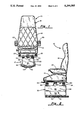
- FIG. 2 is a side view of the vehicle seat of the present invention
- FIG. 3 is a top plan view of the apparatus of FIG. 1 with the upholstered seat and seat back removed and with sections broken away to illustrate the underlying parts;
- FIG. 4 is a rear view of the vehicle seat assembly with the housing's rear panel removed.
- FIG. 5 is a left side view that is partially broken away to illustrate internal parts.
- the assembly itself is indicated generally by numeral 10, and includes a base or pedestal 12 having an upholstered seat 14
- the upholstered seat is conventional and includes a seat cushion 16 and a seat back 18.
- the seat back and cushion include appropriately contoured foam material which is covered by a suitable decorative and functional fabric.
- Arm rests 20 and 22 may also be provided. These are designed to be swung in the horizontal disposition shown to a vertical disposition generally aligned with the seat back 18.
- the bottom panel of the seat cushion 16 is fastened to a pair of slide rails 24 and 26.
- the driver or occupant may set the seat position at a desired location in the fore and aft direction to accommodate the occupant's stature.
- the seat pedestal is seen to comprise a box-like housing 30 having a front panel 32, left and right side panels 34 and 36, and a rear panel 38, each of which project vertically upward from a floor member 40. Disposed beneath it is a mounting plate 42 which is adapted to be bolted to the floor of the vehicle. Left and right box-like covers 44 and 46 extend the length of the pedestal along the sides 34 and 36 and serve to shield or house a slide assembly, all as will be more fully described as the description of the preferred embodiment progresses.
- FIG. 2 it can be seen that there is centrally disposed within the box-like housing 30 a vertically oriented air spring 48 operatively connected between the floor 40 of the housing and a vertically displaceable plate 50 on which the slide assemblies 24 and 26 are attached.
- a vertically oriented air spring 48 operatively connected between the floor 40 of the housing and a vertically displaceable plate 50 on which the slide assemblies 24 and 26 are attached.
- inflation and deflation of the air spring 48 function to raise and lower the seat 14.
- Also disposed between the floor 40 and the plate 50 and contained within the box-like housing 30 are three hydraulic dampeners 52, 54 and 56.
- the mounting plate 42 is seen to comprise a channel having a base 58 which is arranged to abut the floor of the vehicle and which includes appropriately tapped and threaded holes (not shown), allowing the seat to be bolted securely to the floor of the vehicle.
- Bolts 60 and nuts 62 passing through flanges formed on the terminal ends of the up-turned portions of the base plate 58 secure the base plate to transversely extending front and rear bearing support bars 64 and 66, respectively.
- bearing blocks 68 and 70 Attached to the upper surface of the transversely extending bars 64 and 66 are bearing blocks 68 and 70 and which are best visible in the side view of FIG. 5. Similar bearing blocks (not shown) are disposed on the right end portions of the transversely extending bearing support bars 64 and 66 also.
- the bearing blocks 68 and 70 include sleeve bearings 72 and 74 in which is received a smooth, polished cylindrical slide rod, such as slide rod 76 therethrough.
- slide rod 76 passes through the bores of the bearing blocks on the right side of the pedestal assembly as well.
- the slide rod 76 is supported at each end by reinforcing bars 78 and 80 which extend along the lower edge of the front and rear panels 32 and 38, respectively. It can be appreciated, now, that the box-like housing 30 is capable of reciprocating in the fore and aft direction relative to the mounting plate 42.
- Bracket 82 Attached to the upper surface of the bearing block 68 is a bracket 82.
- a tension spring 84 extends between it and the rear enforcing bar 80. The spring thus urges the box-like housing 30 toward the front of the vehicle in which the present invention is installed.
- An identical spring arrangement is disposed on the right side of the housing within the shield 46.
- Affixed to the floor 40 of the housing 30 is a bracket 86. It has a pedestal surface 88 and opposed downwardly and outwardly extending legs 90 and 92. The terminal portion of the legs 90 and 92 are bent to form flanges 94 and 96 which are bolted or welded to the floor 40 of the housing.
- Affixed to the pedestal portion 88 of the bracket 86 is the vertically oriented air spring 48.
- valve 102 includes a pneumatic fitting 98 having a hose 100 leading to a three-positioned valve 102.
- the valve 102 is controlled by a linkage arm 104 which couples it to the plate 50 to which the slide brackets 24 and 26 are joined.
- the valve may be shifted between its three positions. In a first position, the down position, air is allowed to flow through the hose 100 to inflate the air spring 48 causing the plate to be elevated.
- the linkage is in its up position, air is bled from the air spring 48 causing the plate 50 to move downward.
- the linkage is in its intermediate position, air neither enters nor leaves the air spring 48, thus maintaining the seat in its normal or neutral position.
- the cylinders 112 of the three dampeners are bolted at their lower ends to the floor 40 of the box-like housing 30. They extend upward and pass through circular openings formed in cover plates 41 and 43 which extend between and are welded to the upper side walls of the side panels 34 and 36.
- a rubber grommet as at 110 fits into each of the openings and surrounds the cylinder portion 112 of the dampeners.
- Clamping plates 114 and 116 abut the upper surface of the cylinders 112.
- the clamping plates 114 and 116 include a cylindrical bore or aperture therethrough sufficiently large to permit the piston rods 120 and 122 to pass therethrough.
- the upper ends of the piston rods 120 and 122 are affixed to the vertically movable plate 50, and thus are effectively in parallel with the vertically oriented air spring 48.
- the cylinder 112 of the hydraulic dampener 52 located near the front panel 32 of the box-like enclosure is clamped in place using a clamping plate 124 and a pair of bolts passing through it and into the transversely extending top plate 43.
- the piston rod 126 of the cylinder 52 also attaches to the support plate 50 at the front of the pedestal.
- the floor 40 of the box-like enclosure is seen to have a rectangular opening 128 formed through it which exposes the longitudinally extending center brace 130 beneath it.
- the center brace 130 is integrally formed with the transversely extending plates 64 and 66 to effectively form a letter H pattern.
- a L-shaped bracket 132 having reinforcing side gussets 134 is bolted to the strap member 130 by bolts 136. Bracket 132 projects upwardly through the rectangular opening 128 and acts as a stop and support for the forward end of a horizontally oriented air sleeve type spring 138.
- the other end of the air spring 138 is affixed to and supported by the transversely extending vertical plate 80 extending along the rear face of the box or housing 30.
- the air spring 138 is thus effectively coupled in parallel with the tension springs 84 and the slide rods inside the protective shields 44 and 46.
- a suitable tube 140 couples the air spring 138 to a manually operated control valve having an actuating knob 142. That control valve is also coupled by a suitable pneumatic hose to a source of compressed air, such as the supply used in conjunction with the vehicle's air brake system. a pressure regulator may be used to adapt the vehicle's pressure system to the air springs 48 and 138. By manipulating the knob 142, the cushioning effect of the air spring 138 can be adjusted so as to effectively dampen out the vibrational motions in the fore and aft direction which may be encountered during over-the-road travel.
- the slide rails 24 and 26 for supporting the upholstered seat 16 on the vertically moveable plate 50 comprise an upper C-shaped channel 144 and 145 bolted to the underside of the seat 16.
- the elongated C-shaped channels fit over the outwardly extending flanges of U-shaped channels 146 and 147 which are bolted to the upper surface of the vertically moveable plate 50. Because of the manner in which the channels 144-145 and 146-147 interact, the two can slide back and forth relative to one another but cannot be separated except by sliding the two apart at their respective ends.
- the lower U-shaped channel 147 has a plurality of notches 148 formed at regularly spaced intervals along its length. The top view of FIG.
- FIG. 3 shows a latch plate 150 pivotally joined by a rivet or pin 152 to the upper surface of the C-shaped channel 145.
- the lever 28 joins to the latch plate 150 which also has a pair of fingers 154 positioned to penetrate through a pair of adjacent notches 148 when the latch plate 150 is urged to the position shown in FIG. 3 by the spring 156.
- the operator may displace the actuator lever handle 28 relative to the side of the seat and, in doing so, will pivot the latch member 150 about a pin 152 causing fingers 154 on latch member 150 to disengage from a pair of the notches 148 formed through the wall of the channel member 147 attached to the upper surface of the plate 50. With the fingers disengaged, the seat may be slid forward or rearward to a desired position. Releasing the lever 28 allows the return spring 156 to pull the fingers 154 of the latch plate 150 back into engagement with the serrated openings on the slide member 147, thus again locking the mating slide channels to one another.
- the vertically directed air spring 48 along with the three hydraulic dampeners 52, 54 and 56 are used to dampen out any vertically directed forces which the vehicle may encounter, thus tending to isolate the occupant of the seat assembly from vertically directed shock and vibration. For example, upon hitting a bump in the road, a tendency exists for the seat 16 and the occupant to be lifted relative to the truck's floor. The upward motion of the seat operates the automatic three-way valve 102 to release air from the vertically directed air spring 48, thus allowing the seat to fall slightly.
- the truck should encounter a depression in the road, such as, for example, a pot hole, there is a downward directed force which causes the automatic valve to a position in which more air is introduced into the spring 48 to lift the seat relative to its base.
- the downwardly directed force is compensated for by an upward movement of the seat due to inflation of the air spring 48.
- the hydraulic cylinders 52, 54 and 56 not only maintain the bottom of the seat in a level plane, but they tend to dampen out any tendency for the seat to vibrate or oscillate due to sudden vertically directed forces impinging on the seat.
- Each of the dampeners employed include a cylinder that is filled with a heavy oil or grease.
- a ball-shaped piston contained within the cylinder has a predetermined clearance between its surface and the walls of the cylinder containing it. As the piston moves downward, it attempts to compress ht grease, thus extruding it through the clearance space between the piston and cylinder. Likewise, when the piston attempts to move upward, the grease is extruded through the space between the piston and cylinder yielding a resistance to movement and providing the desired dampening effect.
- the present invention provides an improved, flexible and efficient apparatus for mounting a seat within a motor vehicle which functions to effectively isolate the occupant from bearing shock and vibration commonly encountered by semi-truck drivers. The result is that there is less fatigue experienced by the driver and improved highway safety.
Landscapes
- Engineering & Computer Science (AREA)
- Aviation & Aerospace Engineering (AREA)
- Transportation (AREA)
- Mechanical Engineering (AREA)
- Seats For Vehicles (AREA)
Abstract
Description
Claims (17)
Priority Applications (2)
| Application Number | Priority Date | Filing Date | Title |
|---|---|---|---|
| US07/973,885 US5294085A (en) | 1992-11-10 | 1992-11-10 | Shock and vibration isolation apparatus for motor vehicle seats |
| US08/291,980 USRE35572E (en) | 1992-11-10 | 1994-08-17 | Shock and vibration isolation apparatus for motor vehicle seats |
Applications Claiming Priority (1)
| Application Number | Priority Date | Filing Date | Title |
|---|---|---|---|
| US07/973,885 US5294085A (en) | 1992-11-10 | 1992-11-10 | Shock and vibration isolation apparatus for motor vehicle seats |
Related Child Applications (1)
| Application Number | Title | Priority Date | Filing Date |
|---|---|---|---|
| US08/291,980 Reissue USRE35572E (en) | 1992-11-10 | 1994-08-17 | Shock and vibration isolation apparatus for motor vehicle seats |
Publications (1)
| Publication Number | Publication Date |
|---|---|
| US5294085A true US5294085A (en) | 1994-03-15 |
Family
ID=25521336
Family Applications (2)
| Application Number | Title | Priority Date | Filing Date |
|---|---|---|---|
| US07/973,885 Ceased US5294085A (en) | 1992-11-10 | 1992-11-10 | Shock and vibration isolation apparatus for motor vehicle seats |
| US08/291,980 Expired - Lifetime USRE35572E (en) | 1992-11-10 | 1994-08-17 | Shock and vibration isolation apparatus for motor vehicle seats |
Family Applications After (1)
| Application Number | Title | Priority Date | Filing Date |
|---|---|---|---|
| US08/291,980 Expired - Lifetime USRE35572E (en) | 1992-11-10 | 1994-08-17 | Shock and vibration isolation apparatus for motor vehicle seats |
Country Status (1)
| Country | Link |
|---|---|
| US (2) | US5294085A (en) |
Cited By (43)
| Publication number | Priority date | Publication date | Assignee | Title |
|---|---|---|---|---|
| US5652704A (en) * | 1995-09-12 | 1997-07-29 | Lord Corporation | Controllable seat damper system and control method therefor |
| US5761184A (en) * | 1996-04-22 | 1998-06-02 | W. L. Gore & Associates, Inc. | Vibration damping article |
| US6059253A (en) * | 1996-05-14 | 2000-05-09 | Sears Manufacturing Company | Active suspension system for vehicle seats |
| US6199820B1 (en) | 1999-02-04 | 2001-03-13 | Freightliner Llc | Seat suspension system controller |
| US6237889B1 (en) * | 1998-07-16 | 2001-05-29 | Eric Bischoff | Seat suspension assembly |
| US6241209B1 (en) | 1999-02-04 | 2001-06-05 | Freightliner Llc | Seat support |
| US6263527B1 (en) | 1999-10-06 | 2001-07-24 | Scott F. Ross | Sleeper bed for trucks |
| US6286819B1 (en) | 1999-02-04 | 2001-09-11 | Freightliner Corporation Llc | Vibration damper with latch |
| US6354556B1 (en) | 1999-02-04 | 2002-03-12 | Freightliner Llc | Seat suspension method |
| US6371456B1 (en) | 1999-02-04 | 2002-04-16 | Freightliner Llc | Seat suspension system |
| US6505363B2 (en) * | 2000-12-26 | 2003-01-14 | Rocky E. Davis | Device for adjusting the plane of a mattress |
| WO2003076822A1 (en) * | 2002-03-14 | 2003-09-18 | Olav Kaarstein | A device and a system for damping vibrations, impact and shock |
| EP1462303A1 (en) * | 2002-08-21 | 2004-09-29 | Delta Tooling Co., Ltd. | Frame structure of seat for vehicle |
| US20050168046A1 (en) * | 2003-03-26 | 2005-08-04 | Hadi Rod G. | Method and apparatus for dampening vibrations in an assembly of components |
| US6999909B1 (en) | 1999-10-28 | 2006-02-14 | Seagate Technology Llc | Process for designing an optimal vibration isolation mount for a disc drive |
| US7008015B2 (en) | 2003-12-16 | 2006-03-07 | Eric Bischoff | Seat suspension assembly |
| US20070035167A1 (en) * | 2005-08-11 | 2007-02-15 | Meyer William A | Seat assembly |
| US20100096502A1 (en) * | 2008-10-22 | 2010-04-22 | Be Aerospace, Inc. | Tool-less track fastener |
| WO2011061567A1 (en) * | 2009-11-20 | 2011-05-26 | La Nacion, Ministerio De Defensa, Fuerza Aerea Colombiana | Device for reducing vibrations in a helicopter pilot's seat |
| US20110181087A1 (en) * | 2010-01-26 | 2011-07-28 | Mark Kniffin | Active Suspension Seat Skirt |
| US20110181069A1 (en) * | 2010-01-26 | 2011-07-28 | Mark Kniffin | Active Suspension Seat Floor Plate |
| WO2012118814A2 (en) * | 2011-02-28 | 2012-09-07 | Cvg Management Corporation | Pneumatic operated fore/aft vibration isolator locking device |
| US8556341B1 (en) | 2010-03-23 | 2013-10-15 | Kenneth G. Connaughty | Vehicular seat shock absorbing module |
| DE102013021561A1 (en) * | 2013-12-16 | 2015-06-18 | Grammer Ag | Vehicle seat with a horizontally movable seat to accommodate a person |
| US9371882B2 (en) | 2013-10-01 | 2016-06-21 | Grammer Ag | Shock absorber |
| US9377074B2 (en) | 2013-06-26 | 2016-06-28 | Grammer Ag | Device comprising a suspension system |
| CN106427703A (en) * | 2016-12-02 | 2017-02-22 | 合肥工业大学 | Automobile seat achieving active balancing |
| US9849816B2 (en) | 2013-06-04 | 2017-12-26 | Grammer Ag | Vehicle seat and motor vehicle or utility motor vehicle |
| US9879744B2 (en) | 2013-10-01 | 2018-01-30 | Grammer Ag | Vehicle with force-controlled shock absorber with regulating valve |
| US9937832B2 (en) | 2013-10-01 | 2018-04-10 | Grammer Ag | Vehicle seat or vehicle cabin having a suspension apparatus and utility vehicle |
| US9994239B2 (en) | 2013-10-01 | 2018-06-12 | Grammer Ag | Vehicle with force-controlled shock absorber (2-pipe shock absorber) |
| US10046677B2 (en) | 2013-04-23 | 2018-08-14 | Clearmotion Acquisition I Llc | Seat system for a vehicle |
| US10131254B2 (en) * | 2013-03-14 | 2018-11-20 | Alan Bauman | Seat suspension |
| US10160303B2 (en) * | 2016-07-07 | 2018-12-25 | Beijingwest Industries Co., Ltd. | Control system for an active powertrain mount |
| US20190193607A1 (en) * | 2017-12-27 | 2019-06-27 | ErgoAir, Inc, | Pneumatic Seat Support |
| WO2020041643A1 (en) * | 2018-08-22 | 2020-02-27 | BCS Group | Seat frame for securement on a support surface |
| US10682933B2 (en) | 2018-05-16 | 2020-06-16 | Eric Bischoff | Adjustable seat suspension assembly |
| CN113027966A (en) * | 2021-03-01 | 2021-06-25 | 道尔道科技有限公司 | Large-scale spring isolator |
| CN113027967A (en) * | 2021-03-01 | 2021-06-25 | 道尔道科技有限公司 | Upper and lower pressure-bearing box body of spring vibration isolation device for nuclear power steam turbine foundation vibration isolation |
| CN113236709A (en) * | 2021-05-20 | 2021-08-10 | 道尔道科技有限公司 | Large-scale spring isolator pretension compression device |
| CN114601252A (en) * | 2022-03-17 | 2022-06-10 | 北海职业学院 | Outdoor furniture of modularization with multiple different forms |
| US11364826B2 (en) * | 2018-10-30 | 2022-06-21 | Fox Factory, Inc. | Sealed boat seat suspension |
| US11472558B2 (en) | 2018-11-13 | 2022-10-18 | Textron Innovations, Inc. | Aircraft seat |
Families Citing this family (13)
| Publication number | Priority date | Publication date | Assignee | Title |
|---|---|---|---|---|
| US6257663B1 (en) | 1999-04-27 | 2001-07-10 | Richard Swierczewski | Vehicle seat for absorbing impact |
| DE19959411A1 (en) * | 1999-12-09 | 2001-06-21 | Bosch Gmbh Robert | Device and method for adjusting seats in vehicles |
| US6719258B2 (en) | 2002-09-16 | 2004-04-13 | Activar, Inc. | Shock and vibration isolation apparatus for motor vehicles seats |
| EP1468870B1 (en) * | 2003-04-14 | 2006-06-07 | Grammer Ag | Device and method for the suspension of a vehicle seat. |
| US7073865B2 (en) * | 2003-07-03 | 2006-07-11 | Lear Corporation | Tuned vibration absorbing system for a seat system |
| DE102005023088B3 (en) * | 2005-05-13 | 2006-06-22 | Grammer Ag | Suspension for e.g. tractor seat, has controller, where removal and discharging of additional volumes is switched on or deactivated by controller so that distribution of force path spring characteristic line has no or small gradient |
| DE102007048194B4 (en) * | 2007-10-08 | 2014-05-15 | Grammer Aktiengesellschaft | Vehicle with sprung vehicle seat and suspension vehicle cab and suspension method |
| DE102008058409B4 (en) * | 2007-12-04 | 2020-01-23 | Grammer Aktiengesellschaft | Device and method for active suspension of a vehicle part |
| US8240329B1 (en) | 2008-11-14 | 2012-08-14 | Robust Systems Solutions, LLC | Fluid control valve |
| US8585004B1 (en) | 2009-01-26 | 2013-11-19 | Atwood Mobile Products Llc | Air ride seat pedestal with independent height adjustment |
| US8297698B2 (en) * | 2010-03-17 | 2012-10-30 | Richard Swierczewski | Mechatronic vehicle safety seat |
| US9994131B1 (en) | 2017-12-15 | 2018-06-12 | Richard Swierczewski | Preventive self-adjusting structure vehicle seat designed restraint |
| US11772531B1 (en) | 2023-02-15 | 2023-10-03 | Richard Swierczewski | Automatic emergency adjusting vehicle seat |
Citations (26)
| Publication number | Priority date | Publication date | Assignee | Title |
|---|---|---|---|---|
| US3059890A (en) * | 1959-09-03 | 1962-10-23 | Bostrom Corp | Seat for highway trucks |
| US3479099A (en) * | 1967-11-20 | 1969-11-18 | Atwood Vacuum Co | Seat slide structures |
| US3951373A (en) * | 1975-02-18 | 1976-04-20 | Milsco Manufacturing Company | Vehicle seat having valve controlled air spring |
| US3954245A (en) * | 1975-03-03 | 1976-05-04 | Lear Siegler, Inc. | Vehicle seat and support assembly therefor |
| US3990668A (en) * | 1976-01-15 | 1976-11-09 | Deere & Company | Hydraulic suspension seat assembly |
| US4194716A (en) * | 1978-02-27 | 1980-03-25 | American Seating Company | Air suspension driver's seat |
| US4196483A (en) * | 1978-07-19 | 1980-04-08 | Kahl George H Jr | Portable mattress support |
| US4198025A (en) * | 1977-11-29 | 1980-04-15 | Uop Inc. | Vehicle seats |
| US4213594A (en) * | 1977-11-29 | 1980-07-22 | Gerd Lange | Vehicle seat |
| US4363377A (en) * | 1980-09-22 | 1982-12-14 | Deere & Company | Active seat suspension control system |
| US4384700A (en) * | 1980-10-10 | 1983-05-24 | Deere & Company | Velocity sensitive seat damper system |
| US4461444A (en) * | 1980-11-15 | 1984-07-24 | Willibald Grammer | Sprung vehicle seat |
| US4497078A (en) * | 1983-02-14 | 1985-02-05 | Vogel Jerald M | Apparatus for preventing the transmission of vibrations |
| US4589620A (en) * | 1983-12-20 | 1986-05-20 | Tachikawa Spring Co., Ltd. | Seat with an air suspension |
| US4638982A (en) * | 1983-04-07 | 1987-01-27 | Gebr. Isringhausen | Vehicle seat monitoring means |
| US4684100A (en) * | 1985-05-15 | 1987-08-04 | Grammer Sitzsysteme Gmbh | Sprung vehicle seat |
| US4729538A (en) * | 1986-11-10 | 1988-03-08 | Bergacker John W | Apparatus for hydraulically actuating a vehicle seat |
| US4733847A (en) * | 1985-05-15 | 1988-03-29 | Grammer Sitzysteme Gmbh | Sprung vehicle seat |
| US4793583A (en) * | 1986-11-10 | 1988-12-27 | Bergacker John W | Method and apparatus for hydraulically actuating a vehicle seat |
| US4941641A (en) * | 1987-05-22 | 1990-07-17 | Gebr. Isringhausen | Vehicle seat |
| US4954051A (en) * | 1987-10-02 | 1990-09-04 | National Seating Company | Air spring seat and air pump |
| US4969624A (en) * | 1989-11-01 | 1990-11-13 | Vsesojuzny Nauchno-Issledovatelsky Institut Okhrany Truda I Tekhniki Bezopasnosti Chernoi Metallurgii (Vniitbchermet) | Suspension of a vehicle seat |
| US5004206A (en) * | 1990-01-26 | 1991-04-02 | Scott Anderson | Vehicle seat mounting structure |
| US5076529A (en) * | 1991-01-29 | 1991-12-31 | Atwood Industries, Inc. | Seat adjuster with improved crash resistance |
| US5176355A (en) * | 1991-12-09 | 1993-01-05 | Carter John W | Control for height of a seat |
| US5199690A (en) * | 1990-07-26 | 1993-04-06 | M/Rad Corporation | Active vibration isolation system |
-
1992
- 1992-11-10 US US07/973,885 patent/US5294085A/en not_active Ceased
-
1994
- 1994-08-17 US US08/291,980 patent/USRE35572E/en not_active Expired - Lifetime
Patent Citations (26)
| Publication number | Priority date | Publication date | Assignee | Title |
|---|---|---|---|---|
| US3059890A (en) * | 1959-09-03 | 1962-10-23 | Bostrom Corp | Seat for highway trucks |
| US3479099A (en) * | 1967-11-20 | 1969-11-18 | Atwood Vacuum Co | Seat slide structures |
| US3951373A (en) * | 1975-02-18 | 1976-04-20 | Milsco Manufacturing Company | Vehicle seat having valve controlled air spring |
| US3954245A (en) * | 1975-03-03 | 1976-05-04 | Lear Siegler, Inc. | Vehicle seat and support assembly therefor |
| US3990668A (en) * | 1976-01-15 | 1976-11-09 | Deere & Company | Hydraulic suspension seat assembly |
| US4198025A (en) * | 1977-11-29 | 1980-04-15 | Uop Inc. | Vehicle seats |
| US4213594A (en) * | 1977-11-29 | 1980-07-22 | Gerd Lange | Vehicle seat |
| US4194716A (en) * | 1978-02-27 | 1980-03-25 | American Seating Company | Air suspension driver's seat |
| US4196483A (en) * | 1978-07-19 | 1980-04-08 | Kahl George H Jr | Portable mattress support |
| US4363377A (en) * | 1980-09-22 | 1982-12-14 | Deere & Company | Active seat suspension control system |
| US4384700A (en) * | 1980-10-10 | 1983-05-24 | Deere & Company | Velocity sensitive seat damper system |
| US4461444A (en) * | 1980-11-15 | 1984-07-24 | Willibald Grammer | Sprung vehicle seat |
| US4497078A (en) * | 1983-02-14 | 1985-02-05 | Vogel Jerald M | Apparatus for preventing the transmission of vibrations |
| US4638982A (en) * | 1983-04-07 | 1987-01-27 | Gebr. Isringhausen | Vehicle seat monitoring means |
| US4589620A (en) * | 1983-12-20 | 1986-05-20 | Tachikawa Spring Co., Ltd. | Seat with an air suspension |
| US4684100A (en) * | 1985-05-15 | 1987-08-04 | Grammer Sitzsysteme Gmbh | Sprung vehicle seat |
| US4733847A (en) * | 1985-05-15 | 1988-03-29 | Grammer Sitzysteme Gmbh | Sprung vehicle seat |
| US4729538A (en) * | 1986-11-10 | 1988-03-08 | Bergacker John W | Apparatus for hydraulically actuating a vehicle seat |
| US4793583A (en) * | 1986-11-10 | 1988-12-27 | Bergacker John W | Method and apparatus for hydraulically actuating a vehicle seat |
| US4941641A (en) * | 1987-05-22 | 1990-07-17 | Gebr. Isringhausen | Vehicle seat |
| US4954051A (en) * | 1987-10-02 | 1990-09-04 | National Seating Company | Air spring seat and air pump |
| US4969624A (en) * | 1989-11-01 | 1990-11-13 | Vsesojuzny Nauchno-Issledovatelsky Institut Okhrany Truda I Tekhniki Bezopasnosti Chernoi Metallurgii (Vniitbchermet) | Suspension of a vehicle seat |
| US5004206A (en) * | 1990-01-26 | 1991-04-02 | Scott Anderson | Vehicle seat mounting structure |
| US5199690A (en) * | 1990-07-26 | 1993-04-06 | M/Rad Corporation | Active vibration isolation system |
| US5076529A (en) * | 1991-01-29 | 1991-12-31 | Atwood Industries, Inc. | Seat adjuster with improved crash resistance |
| US5176355A (en) * | 1991-12-09 | 1993-01-05 | Carter John W | Control for height of a seat |
Cited By (72)
| Publication number | Priority date | Publication date | Assignee | Title |
|---|---|---|---|---|
| US5652704A (en) * | 1995-09-12 | 1997-07-29 | Lord Corporation | Controllable seat damper system and control method therefor |
| US5761184A (en) * | 1996-04-22 | 1998-06-02 | W. L. Gore & Associates, Inc. | Vibration damping article |
| US6059253A (en) * | 1996-05-14 | 2000-05-09 | Sears Manufacturing Company | Active suspension system for vehicle seats |
| US6237889B1 (en) * | 1998-07-16 | 2001-05-29 | Eric Bischoff | Seat suspension assembly |
| US6199820B1 (en) | 1999-02-04 | 2001-03-13 | Freightliner Llc | Seat suspension system controller |
| US6241209B1 (en) | 1999-02-04 | 2001-06-05 | Freightliner Llc | Seat support |
| US6286819B1 (en) | 1999-02-04 | 2001-09-11 | Freightliner Corporation Llc | Vibration damper with latch |
| US6354556B1 (en) | 1999-02-04 | 2002-03-12 | Freightliner Llc | Seat suspension method |
| US6371456B1 (en) | 1999-02-04 | 2002-04-16 | Freightliner Llc | Seat suspension system |
| US6263527B1 (en) | 1999-10-06 | 2001-07-24 | Scott F. Ross | Sleeper bed for trucks |
| US6999909B1 (en) | 1999-10-28 | 2006-02-14 | Seagate Technology Llc | Process for designing an optimal vibration isolation mount for a disc drive |
| US6505363B2 (en) * | 2000-12-26 | 2003-01-14 | Rocky E. Davis | Device for adjusting the plane of a mattress |
| WO2003076822A1 (en) * | 2002-03-14 | 2003-09-18 | Olav Kaarstein | A device and a system for damping vibrations, impact and shock |
| US7144001B2 (en) | 2002-03-14 | 2006-12-05 | Olav Kaarstein | Device and a system for damping vibrations, impact and shock |
| EP1462303A1 (en) * | 2002-08-21 | 2004-09-29 | Delta Tooling Co., Ltd. | Frame structure of seat for vehicle |
| US20050006937A1 (en) * | 2002-08-21 | 2005-01-13 | Yasuhide Takata | Frame structure of seat for vehicle |
| EP1462303A4 (en) * | 2002-08-21 | 2006-02-01 | Delta Tooling Co Ltd | Frame structure of seat for vehicle |
| US7172251B2 (en) | 2002-08-21 | 2007-02-06 | Delta Tooling Co., Ltd. | Frame structure of seat for vehicle |
| US20050168046A1 (en) * | 2003-03-26 | 2005-08-04 | Hadi Rod G. | Method and apparatus for dampening vibrations in an assembly of components |
| DE102004015494B4 (en) * | 2003-03-26 | 2006-01-05 | Carl Freudenberg Kg | Method and apparatus for vibration damping in a component assembly |
| US7008015B2 (en) | 2003-12-16 | 2006-03-07 | Eric Bischoff | Seat suspension assembly |
| US20070035167A1 (en) * | 2005-08-11 | 2007-02-15 | Meyer William A | Seat assembly |
| US7484799B2 (en) * | 2005-08-11 | 2009-02-03 | Gpv, L.L.C. | Seat assembly |
| US20100096502A1 (en) * | 2008-10-22 | 2010-04-22 | Be Aerospace, Inc. | Tool-less track fastener |
| US8528860B2 (en) * | 2008-10-22 | 2013-09-10 | Be Aerospace, Inc. | Tool-less track fastener |
| CN102858590B (en) * | 2009-11-20 | 2015-09-30 | 哥伦比亚国防部空军 | Shock attenuation unit in helicopter flight person's seat |
| US20120318920A1 (en) * | 2009-11-20 | 2012-12-20 | La Nacion, Ministerio De Defensa Fuerza Aerea Colombiana | Vibrations reduction device in the chairs of helicopter pilots |
| CN102858590A (en) * | 2009-11-20 | 2013-01-02 | 哥伦比亚国防部空军 | Device for reducing vibrations in a helicopter pilot's seat |
| US9061767B2 (en) * | 2009-11-20 | 2015-06-23 | La Nacion, Ministerio De Defensa | Vibrations reduction device in the chairs of helicopter pilots |
| WO2011061567A1 (en) * | 2009-11-20 | 2011-05-26 | La Nacion, Ministerio De Defensa, Fuerza Aerea Colombiana | Device for reducing vibrations in a helicopter pilot's seat |
| RU2504487C1 (en) * | 2009-11-20 | 2014-01-20 | Ля Насьон, Министерио Де Дефенса, Фуерза Аереа Колумбиана | Device to kill vibration of helicopter pilot seat |
| US20110181069A1 (en) * | 2010-01-26 | 2011-07-28 | Mark Kniffin | Active Suspension Seat Floor Plate |
| US20110181087A1 (en) * | 2010-01-26 | 2011-07-28 | Mark Kniffin | Active Suspension Seat Skirt |
| US8282149B2 (en) * | 2010-01-26 | 2012-10-09 | Bose Corporation | Active suspension seat floor plate |
| US8356861B2 (en) | 2010-01-26 | 2013-01-22 | Bose Corporation | Active suspension seat skirt |
| US8556341B1 (en) | 2010-03-23 | 2013-10-15 | Kenneth G. Connaughty | Vehicular seat shock absorbing module |
| US8899559B2 (en) | 2011-02-28 | 2014-12-02 | Cvg Management Corporation | Pneumatic operated fore/aft vibration isolator locking device |
| WO2012118814A3 (en) * | 2011-02-28 | 2013-05-30 | Cvg Management Corporation | Pneumatic operated fore/aft vibration isolator locking device |
| WO2012118814A2 (en) * | 2011-02-28 | 2012-09-07 | Cvg Management Corporation | Pneumatic operated fore/aft vibration isolator locking device |
| US10131254B2 (en) * | 2013-03-14 | 2018-11-20 | Alan Bauman | Seat suspension |
| US10245984B2 (en) | 2013-04-23 | 2019-04-02 | ClearMotion Acquisition LLC | Seat system for a vehicle |
| US10046677B2 (en) | 2013-04-23 | 2018-08-14 | Clearmotion Acquisition I Llc | Seat system for a vehicle |
| US9849816B2 (en) | 2013-06-04 | 2017-12-26 | Grammer Ag | Vehicle seat and motor vehicle or utility motor vehicle |
| US9377074B2 (en) | 2013-06-26 | 2016-06-28 | Grammer Ag | Device comprising a suspension system |
| US9879744B2 (en) | 2013-10-01 | 2018-01-30 | Grammer Ag | Vehicle with force-controlled shock absorber with regulating valve |
| US9937832B2 (en) | 2013-10-01 | 2018-04-10 | Grammer Ag | Vehicle seat or vehicle cabin having a suspension apparatus and utility vehicle |
| US9994239B2 (en) | 2013-10-01 | 2018-06-12 | Grammer Ag | Vehicle with force-controlled shock absorber (2-pipe shock absorber) |
| US9371882B2 (en) | 2013-10-01 | 2016-06-21 | Grammer Ag | Shock absorber |
| US9802520B2 (en) | 2013-12-16 | 2017-10-31 | Grammer Ag | Vehicle seat having a horizontally movable seating surface for receiving a person |
| DE102013021561B4 (en) * | 2013-12-16 | 2020-09-03 | Grammer Ag | Vehicle seat with a horizontally movable seat surface to accommodate a person |
| DE102013021561A1 (en) * | 2013-12-16 | 2015-06-18 | Grammer Ag | Vehicle seat with a horizontally movable seat to accommodate a person |
| US10160303B2 (en) * | 2016-07-07 | 2018-12-25 | Beijingwest Industries Co., Ltd. | Control system for an active powertrain mount |
| CN106427703A (en) * | 2016-12-02 | 2017-02-22 | 合肥工业大学 | Automobile seat achieving active balancing |
| CN106427703B (en) * | 2016-12-02 | 2018-11-23 | 合肥工业大学 | A kind of active balancing automotive seat |
| US20190193607A1 (en) * | 2017-12-27 | 2019-06-27 | ErgoAir, Inc, | Pneumatic Seat Support |
| WO2019133660A1 (en) * | 2017-12-27 | 2019-07-04 | Ergoair, Inc. | Pneumatic seat support |
| US10988060B2 (en) * | 2017-12-27 | 2021-04-27 | Ergoair, Inc. | Pneumatic seat support |
| EP3732074A4 (en) * | 2017-12-27 | 2021-10-20 | Ergoair, Inc. | Pneumatic seat support |
| US10682933B2 (en) | 2018-05-16 | 2020-06-16 | Eric Bischoff | Adjustable seat suspension assembly |
| WO2020041643A1 (en) * | 2018-08-22 | 2020-02-27 | BCS Group | Seat frame for securement on a support surface |
| US11364826B2 (en) * | 2018-10-30 | 2022-06-21 | Fox Factory, Inc. | Sealed boat seat suspension |
| US11858385B2 (en) | 2018-10-30 | 2024-01-02 | Fox Factory, Inc. | Sealed boat seat suspension |
| US11858386B2 (en) | 2018-10-30 | 2024-01-02 | Fox Factory, Inc. | Sealed boat seat suspension |
| US11685530B1 (en) | 2018-11-13 | 2023-06-27 | Textron Innovations, Inc. | Aircraft seat |
| US11472558B2 (en) | 2018-11-13 | 2022-10-18 | Textron Innovations, Inc. | Aircraft seat |
| CN113027967B (en) * | 2021-03-01 | 2022-04-01 | 道尔道科技有限公司 | Upper and lower pressure-bearing box body of spring vibration isolation device for nuclear power steam turbine foundation vibration isolation |
| CN113027966B (en) * | 2021-03-01 | 2022-04-01 | 道尔道科技有限公司 | Large-scale spring isolator |
| CN113027967A (en) * | 2021-03-01 | 2021-06-25 | 道尔道科技有限公司 | Upper and lower pressure-bearing box body of spring vibration isolation device for nuclear power steam turbine foundation vibration isolation |
| CN113027966A (en) * | 2021-03-01 | 2021-06-25 | 道尔道科技有限公司 | Large-scale spring isolator |
| CN113236709B (en) * | 2021-05-20 | 2022-07-08 | 道尔道科技股份有限公司 | Large-scale spring isolator pretension compression device |
| CN113236709A (en) * | 2021-05-20 | 2021-08-10 | 道尔道科技有限公司 | Large-scale spring isolator pretension compression device |
| CN114601252A (en) * | 2022-03-17 | 2022-06-10 | 北海职业学院 | Outdoor furniture of modularization with multiple different forms |
Also Published As
| Publication number | Publication date |
|---|---|
| USRE35572E (en) | 1997-07-29 |
Similar Documents
| Publication | Publication Date | Title |
|---|---|---|
| US5294085A (en) | Shock and vibration isolation apparatus for motor vehicle seats | |
| US6719258B2 (en) | Shock and vibration isolation apparatus for motor vehicles seats | |
| US4941641A (en) | Vehicle seat | |
| EP0921962B1 (en) | Vehicle seat | |
| US3774711A (en) | Vehicle control assembly | |
| US3999800A (en) | Vehicle seat | |
| US5218728A (en) | Vibration isolation apparatus for vehicle sleeper beds | |
| EP2192001B1 (en) | Adjustable vehicle seat suspension | |
| US4497078A (en) | Apparatus for preventing the transmission of vibrations | |
| US7152839B2 (en) | Vehicle seating system with improved vibration isolation | |
| US5799922A (en) | Low profile seat suspension | |
| US4384701A (en) | Fore and aft adjustment and isolation assembly | |
| US3599232A (en) | Vehicle seat suspension system | |
| US4047759A (en) | Compact seat suspension for lift truck | |
| US3371359A (en) | Mattress suspension system | |
| US4397440A (en) | Vehicle seat having height adjustment, automatic weight adjustment and protected ride zone | |
| US20090167057A1 (en) | Tractor Cab Suspension System | |
| US4807713A (en) | Suspension system for truck cabs | |
| EP0407912A2 (en) | Air suspension bed | |
| US5671964A (en) | Vehicle seat mounting mechanism | |
| US4289351A (en) | Low profile truck seat | |
| EP0345439B1 (en) | Vehicle seat | |
| EP0130985B1 (en) | Suspended seat assembly | |
| US4817908A (en) | Seat suspension for underground mining machines | |
| US4194716A (en) | Air suspension driver's seat |
Legal Events
| Date | Code | Title | Description |
|---|---|---|---|
| AS | Assignment |
Owner name: COMFORT RIDE SYSTEMS, INC., MINNESOTA Free format text: ASSIGNMENT OF ASSIGNORS INTEREST.;ASSIGNORS:LLOYD, DAVID;GEISER, RICHARD J.;REEL/FRAME:006386/0067 Effective date: 19921012 |
|
| AS | Assignment |
Owner name: MAC RIDE, INC. Free format text: ASSIGNMENT OF ASSIGNORS INTEREST;ASSIGNOR:COMFORT RIDE SYSTEMS, INC.;REEL/FRAME:006596/0671 Effective date: 19930210 |
|
| STCF | Information on status: patent grant |
Free format text: PATENTED CASE |
|
| RF | Reissue application filed |
Effective date: 19940817 |
|
| FEPP | Fee payment procedure |
Free format text: PAYOR NUMBER ASSIGNED (ORIGINAL EVENT CODE: ASPN); ENTITY STATUS OF PATENT OWNER: SMALL ENTITY |