US5267874A - Connector with wire guiding fixture - Google Patents
Connector with wire guiding fixture Download PDFInfo
- Publication number
- US5267874A US5267874A US08/056,520 US5652093A US5267874A US 5267874 A US5267874 A US 5267874A US 5652093 A US5652093 A US 5652093A US 5267874 A US5267874 A US 5267874A
- Authority
- US
- United States
- Prior art keywords
- wire
- ground
- contacts
- base
- receiving passages
- Prior art date
- Legal status (The legal status is an assumption and is not a legal conclusion. Google has not performed a legal analysis and makes no representation as to the accuracy of the status listed.)
- Expired - Lifetime
Links
Images

Classifications
-
- H—ELECTRICITY
- H01—ELECTRIC ELEMENTS
- H01R—ELECTRICALLY-CONDUCTIVE CONNECTIONS; STRUCTURAL ASSOCIATIONS OF A PLURALITY OF MUTUALLY-INSULATED ELECTRICAL CONNECTING ELEMENTS; COUPLING DEVICES; CURRENT COLLECTORS
- H01R13/00—Details of coupling devices of the kinds covered by groups H01R12/70 or H01R24/00 - H01R33/00
- H01R13/648—Protective earth or shield arrangements on coupling devices, e.g. anti-static shielding
- H01R13/658—High frequency shielding arrangements, e.g. against EMI [Electro-Magnetic Interference] or EMP [Electro-Magnetic Pulse]
- H01R13/6581—Shield structure
- H01R13/6585—Shielding material individually surrounding or interposed between mutually spaced contacts
-
- H—ELECTRICITY
- H01—ELECTRIC ELEMENTS
- H01R—ELECTRICALLY-CONDUCTIVE CONNECTIONS; STRUCTURAL ASSOCIATIONS OF A PLURALITY OF MUTUALLY-INSULATED ELECTRICAL CONNECTING ELEMENTS; COUPLING DEVICES; CURRENT COLLECTORS
- H01R13/00—Details of coupling devices of the kinds covered by groups H01R12/70 or H01R24/00 - H01R33/00
- H01R13/648—Protective earth or shield arrangements on coupling devices, e.g. anti-static shielding
- H01R13/658—High frequency shielding arrangements, e.g. against EMI [Electro-Magnetic Interference] or EMP [Electro-Magnetic Pulse]
- H01R13/6591—Specific features or arrangements of connection of shield to conductive members
- H01R13/6592—Specific features or arrangements of connection of shield to conductive members the conductive member being a shielded cable
Definitions
- the invention relates to a wire organizer for positioning wires of electrical cable, and more particularly, for positioning wires of an electrical cable on pitch spacings of electrical contacts of an electrical connector assembly.
- a connector assembly disclosed in U.S. Pat. No. 4,875,877 comprises, conductive signal contacts for connection to signal wires of at least one electrical cable, wherein, an insulating housing block is applied over the contacts, by injection molding, for example. Windows in the housing block expose the contacts for connection of the contacts with respective wires of at least one electrical cable.
- the insulative housing block is a permanent fixture on the contacts, and is obtained by an injection molding operation that subjects the contacts to an added manufacturing process that adds further complexity to the manufacture of the contacts.
- the invention was developed with an aim to eliminate an added manufacturing process that would add further complexity to the manufacture of the contacts of an electrical connector assembly.
- a wire organizer is manufactured as a separate component part with wire alignment passages constructed for receiving signal wires of one or more electrical cables.
- a further feature of the invention resides in a wire organizer that is a separate component part having wire alignment passages and a base that mounts onto electrical contacts projecting from an electrical connector assembly.
- the passages align one or more signal wires of at least one electrical cable with respective electrical contacts while the wires are joined with the contacts.
- An advantage of the invention resides in a wire organizer that aligns signal wires and electrical contacts of a connector assembly, without a manufacturing operation adding complexity to the manufacture of the contacts.
- Another advantage of the invention resides in a wire organizer that can be mounted, first, onto electrical wires of at least one electrical cable, and second, onto electrical contacts of an electrical connector assembly, to align the wires for joined connection with the contacts.
- a wire organizer for an electrical connector comprises, an insulative base, wire receiving passages crossing the base, respective wire align ground wires and signal wires across the base, and fingers projecting from the base, wherein the fingers align the base with electrical contacts projecting from an electrical connector assembly.
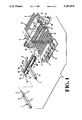
- FIG. 1 is a perspective view of a wire organizer and a connector assembly adapted with the wire organizer, with parts separated from one another:
- FIG. 2 is a side elevation view illustrating the parts shown in FIG. 1 assembled together;
- FIG. 3 is a top plan view of the parts shown in FIG. 2;
- FIG. 4 is an enlarged fragmentary section view of a portion of the wire organizer shown in FIG. 1.
- At least one electrical cable 1 comprises an elongated signal wire 2 or center conductor concentrically encircled by a dielectric 3, in turn, encircled by a flexible insulative outer jacket 4 or sheath.
- a corresponding, elongated and conductive ground wire 5 or drain wire extends along the exterior of the dielectric 3 and is within the jacket 4.
- the cable may include a single ground wire 5, as shown, or may include first and second ground wires 5 to provide a combination of a signal wire 2 between two ground wires 5.
- an electrical connector assembly 6 is to be connected to at least one electrical cable 1 or to multiple electrical cables 1.
- the connector assembly 6 is constructed with at least one row of conductive electrical contacts 9 projecting forwardly from an elongated ground bus 10.
- a series of pilot holes 11 extend through a carrier strip 7.
- a lead frame 12 joins the contacts 9 and the ground bus 10 and the carrier strip 7.
- the contacts 9 are on pitch spacings, that are the repeated spacings between longitudinal axes of the multiple contacts 9 in a row.
- the connector assembly 6 further comprises an insulative housing 13 having cavities 14 on the pitch spacings of the contacts 9.
- the contacts 9 extend along the cavities 14 and project rearwardly of the housing 13.
- Rearward facing latch elements in the form of recesses 15 of rectangular shape in the housing 13 are at opposite ends of the row of contacts 9.
- the connector assembly 6 further comprises a second lead frame 12 comprising, a second row of contacts 9 spaced from the first row of contacts 9, and a second ground bus 10 and a second carrier strip 7 with pilot holes 11 aligned with the pilot holes 11 of the first carrier strip 7.
- each lead frame 12 is joined to the carrier strip 7 by slender links 21 of the contacts 9 extending rearwardly of the housing 13 to the carrier strips 7.
- the slender links 21 are easily bent toward each other to bring the carrier strips 7 together, not shown.
- the slender links 21 of the lead frames 12 can be unbent to maintain the carrier strips 7 separated from each other, as shown in FIG. 1.
- the contacts 9 are constructed to be separated from the ground bus 10. In FIG. 1, selected ones of the contacts 9 have been separated from the ground bus 10, for example, by drilling or punching the contacts 9 to sever them from the ground bus 10, leaving free ends 23 of the contacts 9. At least one electrical contact 9 of the row remains joined to the ground bus 10.
- the ground bus 10 provides a continuous surface for direct connection of a ground wire 5 of at least one electrical cable 1.
- the surfaces of the ground bus 10 and of the contacts 9 are adapted to be joined by direct connection to corresponding ground wires 5 and signal wires 2 by welding, and alternatively, by solder joining.
- Each of the contacts 9 remaining joined to the ground bus 10, and each of the free ends 23 of selected ones of the contacts 9, are to be connected to respective signal wires 2 of at least one electrical cable 1.
- An insulative wire organizer 16 for the electrical connector assembly 6, is of unitary molded construction, and comprises, an insulative base 17, under which multiple contact receiving passages 18 cross the base 17.
- the contact receiving passages are between multiple, spaced apart fingers 19, FIG. 4, that project from and depend from the base 17.
- a hook shaped latch 20 at a tapered tip of each of the fingers 19 faces toward, and overhangs one of the passages 18.
- the fingers 19 align the base 17 with the links 21 of the electrical contacts 2.
- the fingers 19 are resiliently deflectable to move the links 21 past the latches 20 and into the passages 18.
- the latches 20 secure the wire organizer 16 on the links 21 of the contacts 9. Adjacent contacts 9 are separated from one another by the fingers 19.
- Signal wire receiving passages 22 extend across a top of the base 17, concentrically through insulative sleeves 24 on the wire organizer 16.
- the signal wire receiving passages 22 are in superposed alignment with the contact receiving passages 18.
- the signal wire receiving passages 23 and the contact receiving passages 18 are spaced apart on pitch spacings that equal the pitch spacings of the contacts 9.
- Each of the signal wire receiving passages 22 is constructed to receive a signal wire 2 of at least one electrical cable 1 across the base 17.
- Each insulative sleeve 23 that receives a signal wire 2 surrounds the signal wire 2 concentrically, comprising a coaxial construction. Forward open ends 25 of the signal wire receiving passages 22 are in superposed alignment with the contact receiving passages 18. The signal wire 2 projects beyond an open end of the passage 22.
- Each of the signal wire receiving passages 22 that receives a signal wire 2 superposes the signal wire 2 over one of the contacts 9 for joined connection of the signal wire 2 to the contact 9, FIG. 3. For example, the signal wire 2 is joined to the contact 9 by a welding operation or by a soldering operation.
- Ground wire receiving passages 26 of the wire organizer 16 cross the base 17 between adjacent insulative sleeves 23.
- the ground wire receiving passages 26 are aligned with the ground bus 10 projecting rearwardly of the housing 13 of the electrical connector assembly 6.
- Each of the ground wire receiving passages 26 are constructed to receive a ground wire 5.
- Each of the ground wire receiving passages 26 that receives a ground wire 5 of at least one electrical cable 1 superposes the ground wire 5 with the ground bus 10 for joined connection.
- Each ground wire receiving passage 26 is of a channel shape that is different from the shape of the insulative sleeves 24.
- the ground wire receiving passages 26 are shape-coded to distinguish them from the signal wire receiving passages 22, to avoid a mistake of assembling a signal wire 2 along a ground wire receiving passage 26.
- Each of the adjacent insulating sleeves 24 comprises a projecting rib 27 that juts into a ground wire receiving passage 26.
- the rib 27 is constructed to grip a ground wire 5 with an interference fit to secure the cable 1, and to attach the wire organizer 16 to the cable 1.
- the wire organizer 16 can be attached to one cable 1, as in FIG. 1, or multiple cables 1, as in FIG. 3.
- the wire organizer 16 can be attached to one or more cables 1, prior to being mounted on the contacts 9.
- the wire organizer 16 can be mounted on the contacts 9 prior to being attached to one or more cables 1.
- a shelf 28 on the base 17 in front of the insulative sleeves 24 supports each cable 1. More particularly, the dielectric 3 and each ground wire 5 of each cable 1 is supported on the shelf 28.
- the wire organizer 16 is a separate part, and is assembled to the contacts 9, after the contacts 9 have been assembled with the connector assembly 6. Accordingly, the wire organizer 16 aligns each signal wire 2 with one of the contacts 9 without a requirement for modification of the contacts 9.
- Each ground wire 5 is aligned with the ground bus 10 without a requirement for modification of the contacts 9.
Landscapes
- Details Of Connecting Devices For Male And Female Coupling (AREA)
Abstract
Description
Claims (11)
Priority Applications (1)
| Application Number | Priority Date | Filing Date | Title |
|---|---|---|---|
| US08/056,520 US5267874A (en) | 1993-04-28 | 1993-04-28 | Connector with wire guiding fixture |
Applications Claiming Priority (1)
| Application Number | Priority Date | Filing Date | Title |
|---|---|---|---|
| US08/056,520 US5267874A (en) | 1993-04-28 | 1993-04-28 | Connector with wire guiding fixture |
Publications (1)
| Publication Number | Publication Date |
|---|---|
| US5267874A true US5267874A (en) | 1993-12-07 |
Family
ID=22004949
Family Applications (1)
| Application Number | Title | Priority Date | Filing Date |
|---|---|---|---|
| US08/056,520 Expired - Lifetime US5267874A (en) | 1993-04-28 | 1993-04-28 | Connector with wire guiding fixture |
Country Status (1)
| Country | Link |
|---|---|
| US (1) | US5267874A (en) |
Cited By (10)
| Publication number | Priority date | Publication date | Assignee | Title |
|---|---|---|---|---|
| US6004150A (en) * | 1997-12-31 | 1999-12-21 | Cisco Technology, Inc. | Configurable electrical shunt for a computer cable |
| US6217374B1 (en) | 1999-11-18 | 2001-04-17 | Molex Incorporated | Electrical connector with wire management system |
| US6293829B1 (en) | 2000-08-25 | 2001-09-25 | Molex Incorporated | Electrical connector with wire management system |
| US6692273B1 (en) * | 2002-12-31 | 2004-02-17 | Hon Hai Precision Ind. Co., Ltd. | Straddle mount connector |
| US6716057B1 (en) * | 2002-10-03 | 2004-04-06 | Hon Hai Precision Ind. Co., Ltd. | Cable end connector assembly with improved shielding means |
| US20040127078A1 (en) * | 2002-07-22 | 2004-07-01 | Tondreault Robert J | Electronic connector for a cable |
| US20110092110A1 (en) * | 2009-10-20 | 2011-04-21 | Japan Aviation Electronics Industry, Limited | Connector enabling increased density of contacts |
| US8758062B2 (en) * | 2012-06-01 | 2014-06-24 | Alltop Electronics (Suzhou) Ltd. | Cable connector with improved insulative housing |
| US20150318647A1 (en) * | 2014-04-30 | 2015-11-05 | Foxconn Interconnect Technology Limited | Cable connector having improved wire spacer |
| US20170271834A1 (en) * | 2013-11-26 | 2017-09-21 | Samtec, Inc. | Direct-attach connector |
Citations (13)
| Publication number | Priority date | Publication date | Assignee | Title |
|---|---|---|---|---|
| US3958852A (en) * | 1975-04-15 | 1976-05-25 | Bell Telephone Laboratories, Incorporated | Electrical connector |
| US4083615A (en) * | 1977-01-27 | 1978-04-11 | Amp Incorporated | Connector for terminating a flat multi-wire cable |
| US4310208A (en) * | 1979-09-13 | 1982-01-12 | Chabin Corporation | Molded electrical connector |
| US4579404A (en) * | 1983-09-26 | 1986-04-01 | Amp Incorporated | Conductor-terminated card edge connector |
| US4602831A (en) * | 1983-09-26 | 1986-07-29 | Amp Incorporated | Electrical connector and method of making same |
| US4602830A (en) * | 1984-09-20 | 1986-07-29 | Amp Incorporated | Double row electrical connector |
| US4655515A (en) * | 1985-07-12 | 1987-04-07 | Amp Incorporated | Double row electrical connector |
| US4767357A (en) * | 1987-06-10 | 1988-08-30 | E. I. Du Pont De Nemours And Company | Daisy chain connector |
| US4875877A (en) * | 1988-09-12 | 1989-10-24 | Amp Incorporated | Discrete cable assembly |
| US4973264A (en) * | 1986-01-27 | 1990-11-27 | Amp Incorporated | Daisy chain connector |
| US4993968A (en) * | 1989-03-02 | 1991-02-19 | Precision Interconnect Corporation | Economical connector system for an array of conductors |
| US5030138A (en) * | 1990-10-02 | 1991-07-09 | Amp Incorporated | MLG connector for weld termination |
| US5085595A (en) * | 1991-04-05 | 1992-02-04 | Amp Incorporated | Side entry cable assembly |
-
1993
- 1993-04-28 US US08/056,520 patent/US5267874A/en not_active Expired - Lifetime
Patent Citations (13)
| Publication number | Priority date | Publication date | Assignee | Title |
|---|---|---|---|---|
| US3958852A (en) * | 1975-04-15 | 1976-05-25 | Bell Telephone Laboratories, Incorporated | Electrical connector |
| US4083615A (en) * | 1977-01-27 | 1978-04-11 | Amp Incorporated | Connector for terminating a flat multi-wire cable |
| US4310208A (en) * | 1979-09-13 | 1982-01-12 | Chabin Corporation | Molded electrical connector |
| US4579404A (en) * | 1983-09-26 | 1986-04-01 | Amp Incorporated | Conductor-terminated card edge connector |
| US4602831A (en) * | 1983-09-26 | 1986-07-29 | Amp Incorporated | Electrical connector and method of making same |
| US4602830A (en) * | 1984-09-20 | 1986-07-29 | Amp Incorporated | Double row electrical connector |
| US4655515A (en) * | 1985-07-12 | 1987-04-07 | Amp Incorporated | Double row electrical connector |
| US4973264A (en) * | 1986-01-27 | 1990-11-27 | Amp Incorporated | Daisy chain connector |
| US4767357A (en) * | 1987-06-10 | 1988-08-30 | E. I. Du Pont De Nemours And Company | Daisy chain connector |
| US4875877A (en) * | 1988-09-12 | 1989-10-24 | Amp Incorporated | Discrete cable assembly |
| US4993968A (en) * | 1989-03-02 | 1991-02-19 | Precision Interconnect Corporation | Economical connector system for an array of conductors |
| US5030138A (en) * | 1990-10-02 | 1991-07-09 | Amp Incorporated | MLG connector for weld termination |
| US5085595A (en) * | 1991-04-05 | 1992-02-04 | Amp Incorporated | Side entry cable assembly |
Cited By (23)
| Publication number | Priority date | Publication date | Assignee | Title |
|---|---|---|---|---|
| US6254411B1 (en) * | 1997-12-31 | 2001-07-03 | Cisco Technology, Inc. | Configurable electrical shunt for a computer cable |
| US6004150A (en) * | 1997-12-31 | 1999-12-21 | Cisco Technology, Inc. | Configurable electrical shunt for a computer cable |
| CN100345343C (en) * | 1999-11-18 | 2007-10-24 | 莫列斯公司 | Electric connector with electric wire management system |
| EP1102361A2 (en) * | 1999-11-18 | 2001-05-23 | Molex Incorporated | Electrical connector with wire management system |
| EP1102361A3 (en) * | 1999-11-18 | 2001-11-21 | Molex Incorporated | Electrical connector with wire management system |
| US6217374B1 (en) | 1999-11-18 | 2001-04-17 | Molex Incorporated | Electrical connector with wire management system |
| US6293829B1 (en) | 2000-08-25 | 2001-09-25 | Molex Incorporated | Electrical connector with wire management system |
| US20040127078A1 (en) * | 2002-07-22 | 2004-07-01 | Tondreault Robert J | Electronic connector for a cable |
| US6951477B2 (en) * | 2002-07-22 | 2005-10-04 | Rapid Conn, Inc. | Electronic connector for a cable |
| US6716057B1 (en) * | 2002-10-03 | 2004-04-06 | Hon Hai Precision Ind. Co., Ltd. | Cable end connector assembly with improved shielding means |
| US6692273B1 (en) * | 2002-12-31 | 2004-02-17 | Hon Hai Precision Ind. Co., Ltd. | Straddle mount connector |
| US8382527B2 (en) * | 2009-10-20 | 2013-02-26 | Japan Aviation Electronics Industry, Limited | Connector enabling increased density of contacts |
| CN102044783A (en) * | 2009-10-20 | 2011-05-04 | 日本航空电子工业株式会社 | Connector enabling increased density of contacts |
| US20110092110A1 (en) * | 2009-10-20 | 2011-04-21 | Japan Aviation Electronics Industry, Limited | Connector enabling increased density of contacts |
| CN102044783B (en) * | 2009-10-20 | 2013-08-07 | 日本航空电子工业株式会社 | Connector enabling increased density of contacts |
| US9095996B2 (en) | 2009-10-20 | 2015-08-04 | Japan Aviation Electronics Industry, Limited | Connector enabling increased density of contacts |
| US8758062B2 (en) * | 2012-06-01 | 2014-06-24 | Alltop Electronics (Suzhou) Ltd. | Cable connector with improved insulative housing |
| US20170271834A1 (en) * | 2013-11-26 | 2017-09-21 | Samtec, Inc. | Direct-attach connector |
| US20180097326A1 (en) * | 2013-11-26 | 2018-04-05 | Samtec, Inc. | Direct-attach connector |
| US10164394B2 (en) * | 2013-11-26 | 2018-12-25 | Samtec, Inc. | Direct-attach connector |
| US10170882B2 (en) * | 2013-11-26 | 2019-01-01 | Samtec, Inc. | Direct-attach connector |
| US20150318647A1 (en) * | 2014-04-30 | 2015-11-05 | Foxconn Interconnect Technology Limited | Cable connector having improved wire spacer |
| US9484689B2 (en) * | 2014-04-30 | 2016-11-01 | Foxconn Interconnect Technology Limited | Wire spacer for different types of cable wires |
Similar Documents
| Publication | Publication Date | Title |
|---|---|---|
| US4655515A (en) | Double row electrical connector | |
| US4579404A (en) | Conductor-terminated card edge connector | |
| US4697862A (en) | Insulation displacement coaxial cable termination and method | |
| US6171149B1 (en) | High speed connector and method of making same | |
| KR970003363B1 (en) | Connector assembly with series of electrical contacts | |
| US5060372A (en) | Connector assembly and contacts with severed webs | |
| US4781620A (en) | Flat ribbon coaxial cable connector system | |
| US5163849A (en) | Lead frame and electrical connector | |
| US5964620A (en) | Insulation displacement connector | |
| US4533199A (en) | IDC termination for coaxial cable | |
| US5267875A (en) | Electrical connector assembly | |
| US5961348A (en) | System for terminating the shield of a high speed cable | |
| US4790775A (en) | Transition connector | |
| US4632486A (en) | Insulation displacement coaxial cable termination and method | |
| US5618202A (en) | Connector having strip line structure | |
| US6913485B2 (en) | Micro coaxial cable assembly having improved contacts | |
| EP0195050A1 (en) | Double row electrical connector | |
| US8007308B2 (en) | Electrical connector assembly | |
| US4676576A (en) | Communications connector | |
| CN111564723B (en) | Cable connector | |
| US6250959B1 (en) | Connector for coaxial cables with very fine conductors | |
| US5267874A (en) | Connector with wire guiding fixture | |
| EP0542075B1 (en) | Method of terminating miniature coaxial electrical connector and resulting terminated connector | |
| KR930005927Y1 (en) | Multipin connector | |
| US5768771A (en) | System for terminating the shield of a high speed cable |
Legal Events
| Date | Code | Title | Description |
|---|---|---|---|
| AS | Assignment |
Owner name: WHITAKER CORPORATION, THE, DELAWARE Free format text: ASSIGNMENT OF ASSIGNORS INTEREST;ASSIGNORS:KOEGEL, KEITH SCOTT;NEY, REUBEN EARL;ZELKO, WILLIAM EUGENE;AND OTHERS;REEL/FRAME:006536/0008;SIGNING DATES FROM 19930422 TO 19930423 |
|
| STPP | Information on status: patent application and granting procedure in general |
Free format text: APPLICATION UNDERGOING PREEXAM PROCESSING |
|
| FPAY | Fee payment |
Year of fee payment: 4 |
|
| FPAY | Fee payment |
Year of fee payment: 8 |
|
| FEPP | Fee payment procedure |
Free format text: PAYOR NUMBER ASSIGNED (ORIGINAL EVENT CODE: ASPN); ENTITY STATUS OF PATENT OWNER: LARGE ENTITY |
|
| FPAY | Fee payment |
Year of fee payment: 12 |