US5237418A - Audio output circuit in electronic apparatus with composite display function - Google Patents
Audio output circuit in electronic apparatus with composite display function Download PDFInfo
- Publication number
- US5237418A US5237418A US07/754,544 US75454491A US5237418A US 5237418 A US5237418 A US 5237418A US 75454491 A US75454491 A US 75454491A US 5237418 A US5237418 A US 5237418A
- Authority
- US
- United States
- Prior art keywords
- screen
- audio
- signal
- output
- relative
- Prior art date
- Legal status (The legal status is an assumption and is not a legal conclusion. Google has not performed a legal analysis and makes no representation as to the accuracy of the status listed.)
- Expired - Fee Related
Links
Images


Classifications
-
- H—ELECTRICITY
- H04—ELECTRIC COMMUNICATION TECHNIQUE
- H04N—PICTORIAL COMMUNICATION, e.g. TELEVISION
- H04N5/00—Details of television systems
- H04N5/44—Receiver circuitry for the reception of television signals according to analogue transmission standards
- H04N5/60—Receiver circuitry for the reception of television signals according to analogue transmission standards for the sound signals
- H04N5/607—Receiver circuitry for the reception of television signals according to analogue transmission standards for the sound signals for more than one sound signal, e.g. stereo, multilanguages
-
- H—ELECTRICITY
- H04—ELECTRIC COMMUNICATION TECHNIQUE
- H04N—PICTORIAL COMMUNICATION, e.g. TELEVISION
- H04N21/00—Selective content distribution, e.g. interactive television or video on demand [VOD]
- H04N21/40—Client devices specifically adapted for the reception of or interaction with content, e.g. set-top-box [STB]; Operations thereof
- H04N21/43—Processing of content or additional data, e.g. demultiplexing additional data from a digital video stream; Elementary client operations, e.g. monitoring of home network or synchronising decoder's clock; Client middleware
- H04N21/431—Generation of visual interfaces for content selection or interaction; Content or additional data rendering
- H04N21/4312—Generation of visual interfaces for content selection or interaction; Content or additional data rendering involving specific graphical features, e.g. screen layout, special fonts or colors, blinking icons, highlights or animations
- H04N21/4316—Generation of visual interfaces for content selection or interaction; Content or additional data rendering involving specific graphical features, e.g. screen layout, special fonts or colors, blinking icons, highlights or animations for displaying supplemental content in a region of the screen, e.g. an advertisement in a separate window
-
- H—ELECTRICITY
- H04—ELECTRIC COMMUNICATION TECHNIQUE
- H04N—PICTORIAL COMMUNICATION, e.g. TELEVISION
- H04N21/00—Selective content distribution, e.g. interactive television or video on demand [VOD]
- H04N21/40—Client devices specifically adapted for the reception of or interaction with content, e.g. set-top-box [STB]; Operations thereof
- H04N21/47—End-user applications
- H04N21/485—End-user interface for client configuration
- H04N21/4852—End-user interface for client configuration for modifying audio parameters, e.g. switching between mono and stereo
-
- H—ELECTRICITY
- H04—ELECTRIC COMMUNICATION TECHNIQUE
- H04N—PICTORIAL COMMUNICATION, e.g. TELEVISION
- H04N5/00—Details of television systems
- H04N5/44—Receiver circuitry for the reception of television signals according to analogue transmission standards
- H04N5/445—Receiver circuitry for the reception of television signals according to analogue transmission standards for displaying additional information
- H04N5/45—Picture in picture, e.g. displaying simultaneously another television channel in a region of the screen
-
- H—ELECTRICITY
- H04—ELECTRIC COMMUNICATION TECHNIQUE
- H04R—LOUDSPEAKERS, MICROPHONES, GRAMOPHONE PICK-UPS OR LIKE ACOUSTIC ELECTROMECHANICAL TRANSDUCERS; DEAF-AID SETS; PUBLIC ADDRESS SYSTEMS
- H04R5/00—Stereophonic arrangements
- H04R5/04—Circuit arrangements, e.g. for selective connection of amplifier inputs/outputs to loudspeakers, for loudspeaker detection, or for adaptation of settings to personal preferences or hearing impairments
Definitions
- the present invention relates to an audio output circuit in an electronic apparatus equipped with a composite display function. And more particularly, it relates to a novel audio output circuit so contrived that, when audio signals are outputted in an electronic apparatus having a composite display function, any audio signal relative to a desired one of pictures displayed on screen regions can be selectively heard through a speaker, or a plurality of audio signals relative to individual pictures can be heard simultaneously through individual speakers.
- a television receiver a shown in FIG. 8 for example, its entire display screen b is divided into a parent screen b p of a major area and a child screen b c of a minor area defined at the lower left corner, and a picture of another broadcast program or the like different from a picture of the program on the parent screen b p can be displayed on the child screen b c so that both pictures are watchable simultaneously.
- the output from the speaker c in the television receiver a is only the sound relative to the picture on the parent screen b p , so that when it is desired to hear the sound relative to the picture on the child screen b c , a plug of an earphone d needs to be connected each time to an earphone jack in the television receiver to consequently require an additional effort on the part of the user.
- an audio output circuit having an audio signal switching means which switches audio signals relative to pictures being displayed on the individual screens, thereby selecting one of the audio signals and outputting the same to a speaker.
- an audio output circuit having a simultaneous audio output means which is capable of selecting a plurality of audio signals out of those relative to pictures being displayed on the individual screens and then outputting the selected audio signals simultaneously to a plurality of speakers.
- the sounds relative to any desired pictures on the individual screens can be heard either selectively or simultaneously through the speaker(s) in the apparatus irrespectively of the parent screen or the child screen, whereby the known troublesome handling inclusive of the use of an earphone and swapping of the pictures on the parent and child screens can be eliminated at the time of hearing the desired sound(s).
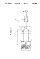
- FIG. 1 is a block diagram showing a fundamental constitution of a first embodiment according to the present invention
- FIG. 2 is a circuit diagram of the first embodiment shown in FIG. 1;
- FIG. 3 illustrates an exemplary audio signal switching operation performed in the first embodiment
- FIG. 4 illustrates another exemplary switching operation performed in the first embodiment
- FIG. 5 is a circuit diagram of a second embodiment of an audio output circuit employed in an electronic apparatus equipped with a composite display function
- FIG. 6 illustrates an exemplary operation performed in the second embodiment
- FIG. 7 illustrates another exemplary operation performed in the second embodiment
- FIG. 8 is a schematic perspective view of a conventional television receiver equipped with a composite display function.
- FIG. 1 is a block diagram showing a fundamental constitution 1 of an audio output circuit in an electronic apparatus equipped with a composite display function.
- an audio circuit 2 for outputting an audio signal relative to a picture on a parent screen
- another audio circuit 3 for outputting an audio signal relative to a picture on a child screen.
- Denoted by 4 is a selective switching circuit wherein one input terminal 4a is connected to an output terminal of the audio circuit 2, and another input terminal 4b is connected to an output terminal of the audio circuit 3.
- the audio signal is supposed here to be monaural, and merely a single signal transmission system is shown.
- the selective switching circuit 4 is actuated under control by a switching control signal (hereinafter referred to as S) in such a manner that, when a microcomputer (not shown) receives a command signal from a depressed remote commander key for deciding which of the audio signals relative to the pictures on the parent and child screens is to be output, a switching control signal S corresponding to such command signal is transmitted from the microcomputer to the switching circuit 4 to thereby control the switching action.
- S switching control signal
- the audio signal selected by the switching circuit 4 is fed from an output terminal 4c to an amplifier 5, and the amplified signal is output from a speaker 6.
- the sound relative to the picture on the parent or child screen is selectively output under control of the switching circuit 4 executed in response to the signal S.
- FIGS. 2 through 4 show the specific constitution of the first embodiment 7 according to the present invention, wherein the sound relative to either of the pictures on the parent and child screens can be selectively output due to the additional provision of another selective switching circuit besides the existing audio switching circuit.
- an audio signal is regarded as a stereophonic signal expressed with subscripts "L” and "R” which represent a left (L) channel and a right (R) channel respectively.
- a L (P-TV) and A R (P-TV) are television audio signals relative to a parent picture selected by a tuner (not shown).
- P-TV stands for a television signal of the parent picture
- C-TV for a television signal of the child picture.
- a L (VIDEOi) and A R (VIDEOi) are external input audio signals which, for example, are playback signals obtained from an external apparatus such as a video tape recorder, a laser disc player or the like.
- the switching circuit 9 is selectively actuated under control by a switching control signal S9, so that the selected audio signals are fed from the output terminals 9 0 L and 9 0 R to a selective switching circuit 10 in the next stage.
- Input terminals 10 2 L and 10 2 R are connected respectively to the output terminals 9 0 L and 9 0 R of the switching circuit 9 and are supplied with the audio signals selected by the switching circuit 9.
- the switching circuit 10 is selectively actuated under control by a switching control signal S10, so that the selected audio signals are fed via output terminals 10 0 L and 10 0 R to an amplifier 11, and thereafter the amplified signals are output respectively from the speakers 12L and 12R.
- the operation of the aforementioned audio output circuit 7 is performed in the following manner.
- a control signal S10 is supplied to the switching circuit 10 for connecting its contacts to the terminals 10 2 L and 10 2 R , and the state of connection in the switching circuit 9 is changed by the control signal S9 to thereby select the desired audio signal.
- the switching circuits 9 and 10 are selectively changed as follows.
- audio signals A L (C-TV) and A R (C-TV) are output respectively from the speakers 12L and 12R by connecting the contacts of the switching circuit 10 to the terminals 10 1 L and 10 1 R .
- FIG. 3 schematically illustrates an exemplary state where, in case the video signal of the parent screen 13 is P-TV and the video signal of the child screen 14 is C-TV, audio.
- the contacts of the switching circuit 10 are selectively connected to the terminals 10 2 L and 10 2 R , and the audio signal of the child screen is selected through the switching circuit 9 to be thereby output.
- VIDEO1 is selected as the video signal of the parent screen 13 and VIDE02 is selected as the video signal of the child screen 14.
- the audio signal relative to the picture on the parent screen is to be output in the above exemplary case, first the contacts of the switching circuit 10 are selectively connected to the terminals 10 2 L and 10 2 R, and the contacts of the switching circuit 9 are selectively connected to the terminals 9 2 L and 9 2 R. Then the audio signals A L (VIDEO1) and A R (VIDEO1) are output from the speakers 12L and 12R respectively via the amplifier 11.
- the contacts of the switching circuit 10 are left unchanged at the terminals 10 2 L and 10 2 R, and the contacts of the switching circuit 9 are selectively connected to the terminals 9 3 L and 9 3 R, whereby the audio signals AI(VIDE02) and A R (VIDE02) are output from the speakers 12L and 12R respectively.
- Table 1 given below lists combinations of video signals relative to the parent and child screens, and the states of selection of audio signals conforming thereto.
- SW9 and SW10 represent the contact connection states of the switching circuits 9 and 10, respectively.
- reference numerals indicating such connection states of SW9 and SW10 signify the values of superscripts in the input terminals 9 j L(R) and 10 j L(R) selected respectively in the switching circuits 9 and 10.
- the sign "-" indicates an indefinite state signifying that some one of the input terminals 9 j L(R) is selected.
- FIGS. 5 through 7 show a second embodiment of the present invention so contrived that sounds relative to the pictures on both parent and child screens can be heard simultaneously as monaural audio signals.
- the same component elements as those employed in the aforementioned first embodiment 7 are denoted by the same reference numerals or symbols, and both video and audio signals in the following description are represented by the same reference symbols as those used in regard to the first embodiment 7.
- the switching circuit 15 further has four output terminals 15 0 L, 15 0 R, 15 M , 15 M' of a four-contact structure. However, since the terminals 15 0 L and 15 0 R constitute one pair while the terminals 15 M and 15 M constitute another pair, a two-contact structure is formed substantially.
- Denoted by 16 is another selective switching circuit provided in a next stage and controlled by two-system switching control signals DS16. This circuit has seven input terminals.
- Audio signals A L (C-TV) and A R (C-TV) are fed to the input terminals 16 1 L and 16 1 R respectively, and signals from the output terminals 15 0 L and 15 0 R of the switching circuit 15 are fed to the input terminals 16 2 L and 16 2 R.
- a monaural audio signal A M (C-TV) obtained by mixing stereo audio signals A L (C-TV) and A R (C-TV) is fed to the input terminal 16 3 , while a monaural signal obtained by mixing stereo signals from the output terminal 15 0 L and 15 0 R of the switching circuit 15 is fed to the input terminal 16 4 .
- the input terminal 16 5 is connected to the output terminals)15 M and 15 M ' of the switching circuit 15 and is fed with a monaural signal.
- 16 0 L and 16 0 R are output terminals.
- the switching circuit 16 has a two-contact structure and is so formed that the contact connection states thereof are controllable independently of each other by the switching control signals DS16. (In other words, the individual contacts are not always paired when switched.)
- Such operation is performed in a case where the audio signal relative to the picture on the parent screen is output from one speaker 12R while the audio signal relative to the picture on the child screen is output from the other speaker 12L so that both audio signals are heard simultaneously.
- This status is effective in a split display mode where, as illustrated in FIGS. 6 and 7, the entire television screen is divided into two regions for displaying different pictures thereon.
- a right half region 18 of the entire television screen 17 is used as a parent screen, while a left half region 19 thereof is used as a child screen.
- a left half region 19 thereof is used as a child screen.
- the areas of both screen regions are equal to each other in this example, the distinction between parent and child is merely for the sake of convenience.
- the video signal relative to the parent screen is P-TV
- the video signal relative to the child screen is C-TV.
- the selective switching circuit 15 is so changed that the input terminal 15 1 L is connected to the output terminal 15 M , and the input terminal 15 1 R is connected to the output terminal 15 M' .
- the state of connection between the input terminals and the output terminals 15 0 L, 15 0 R is indefinite and not concerned with the operation.
- one output terminal 16 0 L is connected to the input terminal 16 3
- the other output terminal 16 0 R is connected to the input terminal 16 5 .
- the monaural signal A M (P-TV) obtained by mixing the audio signals A L (P-TV) and A R (P-TV) is outputted from the right speaker 12R, while the monaural audio signal A M (C-TV) is outputted from the left speaker 12L.
- the input terminals 15 2 L and 15 2 R are connected respectively to the output terminals 15 0 L and 15 0 R in the switching circuit 15, and the input terminals 15 4 L and 15 4 R are connected respectively to the output terminals 15 M and 15 M' .
- the input terminal 16 4 is connected to the output terminal 16 0 L, and the input terminal 16 5 is connected to the output terminal 16 0 R.
- the monaural audio signal A M (VIDE03) relative to the video signal VIDE03 is output from the right speaker 12R, while the monaural audio signal A M (VIDEO1) relative to the video signal VIDEO1 is output from the left speaker 12L.
- SW15 represents the contact connection state of the switching circuit 15
- S M signifies the connection state between the output terminals 15 M , 15 M' and the input terminals
- S LR signifies the connection state between the output terminals 15 0 L, 15 0 R and the input terminals.
- SW16 represents the contact connection state of the switching circuit 16
- S R signifies the connection state between the output terminal 16 0 R and the input terminal
- S L signifies the connection state between the output terminal 16 0 L and the input terminal.
- any audio signal(s) relative to the picture(s) displayed on the individual screen region(s) can be heard either selectively or simultaneously through the speaker(s) irrespectively of the parent or child screen, so that the troublesome handling in the conventional apparatus can be eliminated in hearing any desired sound.
Abstract
Description
              TABLE 1
______________________________________
          Stereo audio signal
Video signal
            When parent screen
                           When child screen
Parent Child    signal is outputted
                               signal is outputted
screen screen   SW9      SW10    SW9    SW10
______________________________________
P-TV or
       C-TV     One of   2       --     1
VIDEO           1-4
1-3
P-TV   VIDEO1   1        2       2      2
       VIDEO2   1        2       3      2
       VIDEO3   1        2       4      2
VIDEO1 VIDEO2   2        2       3      2
       VIDEO3   2        2       4      2
VIDEO2 VIDEO1   3        2       2      2
       VIDEO3   3        2       4      2
VIDEO3 VIDEO1   4        2       2      2
       VIDEO2   4        2       3      2
______________________________________
______________________________________
output terminals     15.sup.0 L → 9.sup.0 L
                     15.sup.0 R → 9.sup.0 L
input terminals      16.sup.1 L → 10.sup.1 L
                     16.sup.1 R → 10.sup.1 R
                     16.sup.2 L → 10.sup.2 L
                     16.sup.2 R → 10.sup.2 R
______________________________________
              TABLE 2
______________________________________
          Monaural audio signal
Video signal
            When parent (right)
                           When child (left)
Parent Child    signal is outputted
                               signal is outputted
(right)
       (left)   SW15     SW16    SW15   SW16
screen screen   S.sub.M  S.sub.R S.sub.LR
                                        S.sub.L
______________________________________
P-TV or
       C-TV     One of   5       --     3
VIDEO           1-4
1-3
P-TV   VIDEO1   1        5       2      4
       VIDEO2   1        5       3      4
       VIDEO3   1        5       4      4
VIDEO1 VIDEO2   2        5       3      4
       VIDEO3   2        5       4      4
VIDEO2 VIDEO1   3        5       2      4
       VIDEO3   3        5       4      4
VIDEO3 VIDEO1   4        5       2      4
       VIDEO2   4        5       3      4
______________________________________
Claims (1)
Applications Claiming Priority (2)
| Application Number | Priority Date | Filing Date | Title |
|---|---|---|---|
| JP2-234225 | 1990-09-04 | ||
| JP2234225A JPH04114576A (en) | 1990-09-04 | 1990-09-04 | Sound output circuit for electronic unit provided with screen synthesis function |
Publications (1)
| Publication Number | Publication Date |
|---|---|
| US5237418A true US5237418A (en) | 1993-08-17 |
Family
ID=16967658
Family Applications (1)
| Application Number | Title | Priority Date | Filing Date |
|---|---|---|---|
| US07/754,544 Expired - Fee Related US5237418A (en) | 1990-09-04 | 1991-09-04 | Audio output circuit in electronic apparatus with composite display function |
Country Status (2)
| Country | Link |
|---|---|
| US (1) | US5237418A (en) |
| JP (1) | JPH04114576A (en) |
Cited By (57)
| Publication number | Priority date | Publication date | Assignee | Title |
|---|---|---|---|---|
| WO1996013120A1 (en) * | 1994-10-25 | 1996-05-02 | Thomson Consumer Electronics, Inc. | Use of an audio processing channel in a television receiver during a multipicture mode of operation |
| EP0732847A2 (en) * | 1995-03-17 | 1996-09-18 | Kabushiki Kaisha Toshiba | Multi-screen television receiver |
| US5602598A (en) * | 1992-12-02 | 1997-02-11 | Sony Corporation | Television receiver with caption display |
| US5760842A (en) * | 1995-05-30 | 1998-06-02 | Samsung Electronics Co., Ltd. | Method of selecting input/output source in double/wide television set and apparatus therefor |
| US6028599A (en) * | 1994-08-31 | 2000-02-22 | Yuen; Henry C. | Database for use in method and apparatus for displaying television programs and related text |
| US6118493A (en) * | 1997-04-01 | 2000-09-12 | Ati Technologies, Inc. | Method and apparatus for selecting a channel from a multiple channel display |
| EP1073270A1 (en) * | 1999-07-30 | 2001-01-31 | Deutsche Thomson-Brandt Gmbh | Method and apparatus for navigation through multimedia presentations |
| EP1093302A2 (en) * | 1999-10-15 | 2001-04-18 | Matsushita Electric Industrial Co., Ltd. | Multichannel display data generating apparatus, and data medium, and computer program therefor |
| WO2001074050A2 (en) * | 2000-03-29 | 2001-10-04 | Digeo Broadband, Inc. | System and method for picture-in-browser scaling |
| US6323911B1 (en) * | 1995-10-02 | 2001-11-27 | Starsight Telecast, Inc. | System and method for using television schedule information |
| FR2814891A1 (en) * | 2000-10-04 | 2002-04-05 | Thomson Multimedia Sa | AUDIO LEVEL ADJUSTMENT METHOD FROM MULTIPLE CHANNELS AND ADJUSTMENT DEVICE |
| US6590618B1 (en) * | 1998-09-14 | 2003-07-08 | Samsung Electronics Co., Ltd. | Method and apparatus for changing the channel or varying the volume level in a television receiver having a double screen mode function |
| US20030192057A1 (en) * | 1997-01-23 | 2003-10-09 | Gaughan Kevin J. | Web television having a two-way communication bus interconnecting a television controller and an internet module |
| US20030189674A1 (en) * | 2002-04-05 | 2003-10-09 | Canon Kabushiki Kaisha | Receiving apparatus |
| US20030197811A1 (en) * | 2002-04-19 | 2003-10-23 | Hoover Alan Anderson | Loudspeaker arrangement and switching apparatus therefor |
| US20040056885A1 (en) * | 2001-03-26 | 2004-03-25 | Fujitsu Limited | Multichannel information processing device |
| US20060075437A1 (en) * | 2004-09-30 | 2006-04-06 | Robert Bambic | Remote jack pack |
| US20060218583A1 (en) * | 2005-03-25 | 2006-09-28 | Alcatel | Interactive displaying system |
| US20060250528A1 (en) * | 2005-05-06 | 2006-11-09 | Jung Chang S | Apparatus and method of receiving digital multimedia broadcasting |
| US20060257109A1 (en) * | 2005-05-12 | 2006-11-16 | Denso Corporation | Multi-video display system |
| US7180476B1 (en) * | 1999-06-30 | 2007-02-20 | The Boeing Company | Exterior aircraft vision system using a helmet-mounted display |
| US20070177743A1 (en) * | 2004-04-08 | 2007-08-02 | Koninklijke Philips Electronics, N.V. | Audio level control |
| US20080231545A1 (en) * | 2005-11-24 | 2008-09-25 | Tencent Technology (Shenzhen) Company Ltd. | Video picture management equipment and method for video picture management |
| US7814421B2 (en) | 1998-05-19 | 2010-10-12 | United Video Properties, Inc. | Program guide system with video window browsing |
| US7941818B2 (en) | 1999-06-28 | 2011-05-10 | Index Systems, Inc. | System and method for utilizing EPG database for modifying advertisements |
| US20110187939A1 (en) * | 2010-01-29 | 2011-08-04 | Kabushiki Kaisha Toshiba | Information processing apparatus and audio output control method of an information processing apparatus |
| US20110205434A1 (en) * | 2010-02-23 | 2011-08-25 | Robert Bambic | Remote jack pack |
| USRE43578E1 (en) | 1999-11-12 | 2012-08-14 | Lg Electronics Inc. | Apparatus and method for downloading and storing data from a digital receiver |
| US8272011B2 (en) | 1996-12-19 | 2012-09-18 | Index Systems, Inc. | Method and system for displaying advertisements between schedule listings |
| US8336071B2 (en) | 1996-12-19 | 2012-12-18 | Gemstar Development Corporation | System and method for modifying advertisement responsive to EPG information |
| US8359616B2 (en) | 2009-09-30 | 2013-01-22 | United Video Properties, Inc. | Systems and methods for automatically generating advertisements using a media guidance application |
| USRE43988E1 (en) | 1999-11-12 | 2013-02-05 | Lg Electronics Inc. | Apparatus and method for providing, retrieving, and using data guide information supplied in a digital vestigial sideband signal |
| GB2495366A (en) * | 2011-08-29 | 2013-04-10 | Hae-Yong Choi | Audio-visual system allowing local selection of audio channels |
| US8613020B2 (en) | 1998-04-30 | 2013-12-17 | United Video Properties, Inc. | Program guide system with flip and browse advertisements |
| US8612310B2 (en) | 2005-12-29 | 2013-12-17 | United Video Properties, Inc. | Method and system for commerce in media program related merchandise |
| US8776125B2 (en) | 1996-05-03 | 2014-07-08 | Starsight Telecast Inc. | Method and system for displaying advertisements in an electronic program guide |
| US8793738B2 (en) | 1994-05-04 | 2014-07-29 | Starsight Telecast Incorporated | Television system with downloadable features |
| US8806536B2 (en) | 1998-03-04 | 2014-08-12 | United Video Properties, Inc. | Program guide system with preference profiles |
| US8832742B2 (en) | 2006-10-06 | 2014-09-09 | United Video Properties, Inc. | Systems and methods for acquiring, categorizing and delivering media in interactive media guidance applications |
| US8863170B2 (en) | 2000-03-31 | 2014-10-14 | United Video Properties, Inc. | System and method for metadata-linked advertisements |
| US8918807B2 (en) | 1997-07-21 | 2014-12-23 | Gemstar Development Corporation | System and method for modifying advertisement responsive to EPG information |
| US8931008B2 (en) | 1999-06-29 | 2015-01-06 | United Video Properties, Inc. | Promotional philosophy for a video-on-demand-related interactive display within an interactive television application |
| US9015750B2 (en) | 1998-05-15 | 2015-04-21 | Rovi Guides, Inc. | Interactive television program guide system for determining user values for demographic categories |
| US9075861B2 (en) | 2006-03-06 | 2015-07-07 | Veveo, Inc. | Methods and systems for segmenting relative user preferences into fine-grain and coarse-grain collections |
| US9113107B2 (en) | 2005-11-08 | 2015-08-18 | Rovi Guides, Inc. | Interactive advertising and program promotion in an interactive television system |
| US9113207B2 (en) | 1995-10-02 | 2015-08-18 | Rovi Guides, Inc. | Systems and methods for contextually linking television program information |
| US9147198B2 (en) | 2013-01-10 | 2015-09-29 | Rovi Technologies Corporation | Systems and methods for providing an interface for data driven media placement |
| US9166714B2 (en) | 2009-09-11 | 2015-10-20 | Veveo, Inc. | Method of and system for presenting enriched video viewing analytics |
| US9172987B2 (en) | 1998-07-07 | 2015-10-27 | Rovi Guides, Inc. | Methods and systems for updating functionality of a set-top box using markup language |
| US9177081B2 (en) | 2005-08-26 | 2015-11-03 | Veveo, Inc. | Method and system for processing ambiguous, multi-term search queries |
| US9319735B2 (en) | 1995-06-07 | 2016-04-19 | Rovi Guides, Inc. | Electronic television program guide schedule system and method with data feed access |
| US9326025B2 (en) | 2007-03-09 | 2016-04-26 | Rovi Technologies Corporation | Media content search results ranked by popularity |
| US9426509B2 (en) | 1998-08-21 | 2016-08-23 | Rovi Guides, Inc. | Client-server electronic program guide |
| US9591251B2 (en) | 1997-10-06 | 2017-03-07 | Rovi Guides, Inc. | Interactive television program guide system with operator showcase |
| US9736524B2 (en) | 2011-01-06 | 2017-08-15 | Veveo, Inc. | Methods of and systems for content search based on environment sampling |
| US9749693B2 (en) | 2006-03-24 | 2017-08-29 | Rovi Guides, Inc. | Interactive media guidance application with intelligent navigation and display features |
| US9848276B2 (en) | 2013-03-11 | 2017-12-19 | Rovi Guides, Inc. | Systems and methods for auto-configuring a user equipment device with content consumption material |
Families Citing this family (1)
| Publication number | Priority date | Publication date | Assignee | Title |
|---|---|---|---|---|
| JP3856136B2 (en) * | 2003-05-15 | 2006-12-13 | 船井電機株式会社 | AV system |
Citations (5)
| Publication number | Priority date | Publication date | Assignee | Title |
|---|---|---|---|---|
| US2832821A (en) * | 1954-01-11 | 1958-04-29 | Du Mont Allen B Lab Inc | Dual image viewing apparatus |
| US3303279A (en) * | 1962-08-20 | 1967-02-07 | Frost L Tinklepaugh | Prepaid entertainment distribution system |
| US3875674A (en) * | 1972-05-08 | 1975-04-08 | Wilbur J Davidson | Automatic range finding bow sight |
| JPS5330818A (en) * | 1976-09-03 | 1978-03-23 | Hitachi Ltd | Two-picture reproducing television receiver set |
| US5099365A (en) * | 1988-08-08 | 1992-03-24 | Samsung Electronics Co., Ltd. | Circuit for simultaneously generating the sounds of both main picture and sub-picture for a picture-in-picture system of VTR |
-
1990
- 1990-09-04 JP JP2234225A patent/JPH04114576A/en active Pending
-
1991
- 1991-09-04 US US07/754,544 patent/US5237418A/en not_active Expired - Fee Related
Patent Citations (5)
| Publication number | Priority date | Publication date | Assignee | Title |
|---|---|---|---|---|
| US2832821A (en) * | 1954-01-11 | 1958-04-29 | Du Mont Allen B Lab Inc | Dual image viewing apparatus |
| US3303279A (en) * | 1962-08-20 | 1967-02-07 | Frost L Tinklepaugh | Prepaid entertainment distribution system |
| US3875674A (en) * | 1972-05-08 | 1975-04-08 | Wilbur J Davidson | Automatic range finding bow sight |
| JPS5330818A (en) * | 1976-09-03 | 1978-03-23 | Hitachi Ltd | Two-picture reproducing television receiver set |
| US5099365A (en) * | 1988-08-08 | 1992-03-24 | Samsung Electronics Co., Ltd. | Circuit for simultaneously generating the sounds of both main picture and sub-picture for a picture-in-picture system of VTR |
Cited By (111)
| Publication number | Priority date | Publication date | Assignee | Title |
|---|---|---|---|---|
| US5602598A (en) * | 1992-12-02 | 1997-02-11 | Sony Corporation | Television receiver with caption display |
| US8793738B2 (en) | 1994-05-04 | 2014-07-29 | Starsight Telecast Incorporated | Television system with downloadable features |
| US6239794B1 (en) | 1994-08-31 | 2001-05-29 | E Guide, Inc. | Method and system for simultaneously displaying a television program and information about the program |
| US6477705B1 (en) | 1994-08-31 | 2002-11-05 | Gemstar Development Corporation | Method and apparatus for transmitting, storing, and processing electronic program guide data for on-screen display |
| US6028599A (en) * | 1994-08-31 | 2000-02-22 | Yuen; Henry C. | Database for use in method and apparatus for displaying television programs and related text |
| US7996864B2 (en) | 1994-08-31 | 2011-08-09 | Gemstar Development Corporation | Method and apparatus for displaying television programs and related text |
| US5841483A (en) * | 1994-10-25 | 1998-11-24 | Thomson Consumer Electronics, Inc. | Use of an audio processing channel in a television receiver during a multipicture mode of operation |
| EP0982940A1 (en) * | 1994-10-25 | 2000-03-01 | Thomson Consumer Electronics, Inc. | Use of an audio processing channel in a television receiver during a multipicture mode of operation |
| WO1996013120A1 (en) * | 1994-10-25 | 1996-05-02 | Thomson Consumer Electronics, Inc. | Use of an audio processing channel in a television receiver during a multipicture mode of operation |
| EP0732847A2 (en) * | 1995-03-17 | 1996-09-18 | Kabushiki Kaisha Toshiba | Multi-screen television receiver |
| EP0732847A3 (en) * | 1995-03-17 | 1996-12-11 | Toshiba Kk | Multi-screen television receiver |
| US5760842A (en) * | 1995-05-30 | 1998-06-02 | Samsung Electronics Co., Ltd. | Method of selecting input/output source in double/wide television set and apparatus therefor |
| US9319735B2 (en) | 1995-06-07 | 2016-04-19 | Rovi Guides, Inc. | Electronic television program guide schedule system and method with data feed access |
| US9113207B2 (en) | 1995-10-02 | 2015-08-18 | Rovi Guides, Inc. | Systems and methods for contextually linking television program information |
| US6323911B1 (en) * | 1995-10-02 | 2001-11-27 | Starsight Telecast, Inc. | System and method for using television schedule information |
| US8453174B2 (en) | 1995-10-02 | 2013-05-28 | Starsight Telecast, Inc. | Method and system for displaying advertising, video, and program schedule listing |
| US9402102B2 (en) | 1995-10-02 | 2016-07-26 | Rovi Guides, Inc. | System and method for using television schedule information |
| US8181200B2 (en) | 1995-10-02 | 2012-05-15 | Starsight Telecast, Inc. | Method and system for displaying advertising, video, and program schedule listing |
| US9124932B2 (en) | 1995-10-02 | 2015-09-01 | Rovi Guides, Inc. | Systems and methods for contextually linking television program information |
| US8776125B2 (en) | 1996-05-03 | 2014-07-08 | Starsight Telecast Inc. | Method and system for displaying advertisements in an electronic program guide |
| US8869204B2 (en) | 1996-05-03 | 2014-10-21 | Starsight Telecast, Inc. | Method and system for displaying advertisements in an electronic program guide |
| US8732757B2 (en) | 1996-12-19 | 2014-05-20 | Gemstar Development Corporation | System and method for targeted advertisement display responsive to user characteristics |
| US8272011B2 (en) | 1996-12-19 | 2012-09-18 | Index Systems, Inc. | Method and system for displaying advertisements between schedule listings |
| US8726311B2 (en) | 1996-12-19 | 2014-05-13 | Gemstar Development Corporation | System and method for modifying advertisement responsive to EPG information |
| US8448209B2 (en) | 1996-12-19 | 2013-05-21 | Gemstar Development Corporation | System and method for displaying advertisements responsive to EPG information |
| US8336071B2 (en) | 1996-12-19 | 2012-12-18 | Gemstar Development Corporation | System and method for modifying advertisement responsive to EPG information |
| US8635649B2 (en) | 1996-12-19 | 2014-01-21 | Gemstar Development Corporation | System and method for modifying advertisement responsive to EPG information |
| US20090307737A1 (en) * | 1997-01-23 | 2009-12-10 | Gaughan Kevin J | Web television having a two-way communication bus interconnecting a television controller and internet module |
| US20030192057A1 (en) * | 1997-01-23 | 2003-10-09 | Gaughan Kevin J. | Web television having a two-way communication bus interconnecting a television controller and an internet module |
| US9277279B2 (en) | 1997-01-23 | 2016-03-01 | Lg Electronics, Inc. | Web television having a two-way communication bus interconnecting a television controller and an internet module |
| US9241189B2 (en) | 1997-01-23 | 2016-01-19 | Lg Electronics, Inc. | Web television having a two-way communication bus interconnecting a television controller and an internet module |
| US20090282450A1 (en) * | 1997-01-23 | 2009-11-12 | Gaughan Kevin J | Web television having a two-way communication bus interconnecting a television controller and an internet module |
| US20090138927A1 (en) * | 1997-01-23 | 2009-05-28 | Zenith Electronics Corporation | Web television having a two-way communication bus interconnecting a television controller and an internet module |
| US20090100485A1 (en) * | 1997-01-23 | 2009-04-16 | Zenith Electronics Corporation | Web television that swaps television video and internet video in a pip area |
| US20090094655A1 (en) * | 1997-01-23 | 2009-04-09 | Zenith Electronics Corporation | web television having a two-way communication bus interconnecting a television controller and an internet module |
| US20090091657A1 (en) * | 1997-01-23 | 2009-04-09 | Zenith Electronics Corporation | web television that performs a pip control function |
| US6118493A (en) * | 1997-04-01 | 2000-09-12 | Ati Technologies, Inc. | Method and apparatus for selecting a channel from a multiple channel display |
| US8918807B2 (en) | 1997-07-21 | 2014-12-23 | Gemstar Development Corporation | System and method for modifying advertisement responsive to EPG information |
| US9191722B2 (en) | 1997-07-21 | 2015-11-17 | Rovi Guides, Inc. | System and method for modifying advertisement responsive to EPG information |
| US9015749B2 (en) | 1997-07-21 | 2015-04-21 | Rovi Guides, Inc. | System and method for modifying advertisement responsive to EPG information |
| US9591251B2 (en) | 1997-10-06 | 2017-03-07 | Rovi Guides, Inc. | Interactive television program guide system with operator showcase |
| US8806536B2 (en) | 1998-03-04 | 2014-08-12 | United Video Properties, Inc. | Program guide system with preference profiles |
| US8613020B2 (en) | 1998-04-30 | 2013-12-17 | United Video Properties, Inc. | Program guide system with flip and browse advertisements |
| US9635406B2 (en) | 1998-05-15 | 2017-04-25 | Rovi Guides, Inc. | Interactive television program guide system for determining user values for demographic categories |
| US9015750B2 (en) | 1998-05-15 | 2015-04-21 | Rovi Guides, Inc. | Interactive television program guide system for determining user values for demographic categories |
| US7814421B2 (en) | 1998-05-19 | 2010-10-12 | United Video Properties, Inc. | Program guide system with video window browsing |
| US9172987B2 (en) | 1998-07-07 | 2015-10-27 | Rovi Guides, Inc. | Methods and systems for updating functionality of a set-top box using markup language |
| US9426509B2 (en) | 1998-08-21 | 2016-08-23 | Rovi Guides, Inc. | Client-server electronic program guide |
| US6590618B1 (en) * | 1998-09-14 | 2003-07-08 | Samsung Electronics Co., Ltd. | Method and apparatus for changing the channel or varying the volume level in a television receiver having a double screen mode function |
| US7941818B2 (en) | 1999-06-28 | 2011-05-10 | Index Systems, Inc. | System and method for utilizing EPG database for modifying advertisements |
| US8931008B2 (en) | 1999-06-29 | 2015-01-06 | United Video Properties, Inc. | Promotional philosophy for a video-on-demand-related interactive display within an interactive television application |
| US7180476B1 (en) * | 1999-06-30 | 2007-02-20 | The Boeing Company | Exterior aircraft vision system using a helmet-mounted display |
| EP1073270A1 (en) * | 1999-07-30 | 2001-01-31 | Deutsche Thomson-Brandt Gmbh | Method and apparatus for navigation through multimedia presentations |
| EP1093302A3 (en) * | 1999-10-15 | 2004-08-25 | Matsushita Electric Industrial Co., Ltd. | Multichannel display data generating apparatus, and data medium, and computer program therefor |
| US7512962B2 (en) | 1999-10-15 | 2009-03-31 | Panasonic Corporation | Multichannel display data generating apparatus, medium, and informational set |
| US20050259952A1 (en) * | 1999-10-15 | 2005-11-24 | Shoichi Gotoh | Multichannel display data generating apparatus, medium, and informational set |
| EP1093302A2 (en) * | 1999-10-15 | 2001-04-18 | Matsushita Electric Industrial Co., Ltd. | Multichannel display data generating apparatus, and data medium, and computer program therefor |
| US7236531B1 (en) | 1999-10-15 | 2007-06-26 | Matsushita Electric Industrial Co., Ltd. | Display apparatus displaying certain data without a program clock reference |
| USRE45410E1 (en) | 1999-11-12 | 2015-03-10 | Lg Electronics Inc. | Apparatus and method for providing, retrieving, and using data guide information supplied in a digital vestigial sideband signal |
| USRE43671E1 (en) | 1999-11-12 | 2012-09-18 | Lg Electronics Inc. | Apparatus and method for downloading and storing data from a digital receiver |
| USRE44321E1 (en) | 1999-11-12 | 2013-06-25 | Lg Electronics Inc. | Apparatus and method for downloading and storing data from a digital receiver |
| USRE44495E1 (en) | 1999-11-12 | 2013-09-10 | Lg Electronics Inc. | Apparatus and method for providing, retrieving, and using data guide information supplied in a digital vestigial sideband signal |
| USRE44514E1 (en) | 1999-11-12 | 2013-10-01 | Lg Electronics, Inc. | Apparatus and method for providing, retrieving, and using data guide information supplied in a digital vestigial sideband signal |
| USRE45225E1 (en) | 1999-11-12 | 2014-10-28 | Lg Electronics, Inc. | Apparatus and method for providing, retrieving, and using data guide information supplied in a digital vestigial sideband signal |
| USRE44623E1 (en) | 1999-11-12 | 2013-12-03 | Lg Electronics Inc. | Apparatus and method for downloading and storing data from a digital receiver |
| USRE43988E1 (en) | 1999-11-12 | 2013-02-05 | Lg Electronics Inc. | Apparatus and method for providing, retrieving, and using data guide information supplied in a digital vestigial sideband signal |
| USRE44990E1 (en) | 1999-11-12 | 2014-07-01 | Lg Electronics Inc. | Apparatus and method for providing, retrieving, and using data guide information supplied in a digital vestigial sideband signal |
| USRE43578E1 (en) | 1999-11-12 | 2012-08-14 | Lg Electronics Inc. | Apparatus and method for downloading and storing data from a digital receiver |
| WO2001074050A2 (en) * | 2000-03-29 | 2001-10-04 | Digeo Broadband, Inc. | System and method for picture-in-browser scaling |
| WO2001074050A3 (en) * | 2000-03-29 | 2002-03-28 | Digeo Broadband Inc | System and method for picture-in-browser scaling |
| US10015562B2 (en) | 2000-03-31 | 2018-07-03 | Rovi Guides, Inc. | System and method for metadata-linked advertisements |
| US8863170B2 (en) | 2000-03-31 | 2014-10-14 | United Video Properties, Inc. | System and method for metadata-linked advertisements |
| FR2814891A1 (en) * | 2000-10-04 | 2002-04-05 | Thomson Multimedia Sa | AUDIO LEVEL ADJUSTMENT METHOD FROM MULTIPLE CHANNELS AND ADJUSTMENT DEVICE |
| US20040056885A1 (en) * | 2001-03-26 | 2004-03-25 | Fujitsu Limited | Multichannel information processing device |
| US7633487B2 (en) * | 2001-03-26 | 2009-12-15 | Fujitsu Limited | Multichannel information processing device |
| US7518658B2 (en) | 2002-04-05 | 2009-04-14 | Canon Kabushiki Kaisha | Receiving apparatus |
| US7113224B2 (en) * | 2002-04-05 | 2006-09-26 | Canon Kabushiki Kaisha | Receiving apparatus |
| US20030189674A1 (en) * | 2002-04-05 | 2003-10-09 | Canon Kabushiki Kaisha | Receiving apparatus |
| US20060203130A1 (en) * | 2002-04-05 | 2006-09-14 | Canon Kabushiki Kaisha | Receiving Apparatus |
| US20030197811A1 (en) * | 2002-04-19 | 2003-10-23 | Hoover Alan Anderson | Loudspeaker arrangement and switching apparatus therefor |
| US20070177743A1 (en) * | 2004-04-08 | 2007-08-02 | Koninklijke Philips Electronics, N.V. | Audio level control |
| US8600077B2 (en) | 2004-04-08 | 2013-12-03 | Koninklijke Philips N.V. | Audio level control |
| US20060075437A1 (en) * | 2004-09-30 | 2006-04-06 | Robert Bambic | Remote jack pack |
| US20060218583A1 (en) * | 2005-03-25 | 2006-09-28 | Alcatel | Interactive displaying system |
| US7768578B2 (en) * | 2005-05-06 | 2010-08-03 | Pantech & Curitel Communications, Inc. | Apparatus and method of receiving digital multimedia broadcasting |
| US20060250528A1 (en) * | 2005-05-06 | 2006-11-09 | Jung Chang S | Apparatus and method of receiving digital multimedia broadcasting |
| US7825991B2 (en) * | 2005-05-12 | 2010-11-02 | Denso Corporation | Multi-video display system |
| US20060257109A1 (en) * | 2005-05-12 | 2006-11-16 | Denso Corporation | Multi-video display system |
| US9177081B2 (en) | 2005-08-26 | 2015-11-03 | Veveo, Inc. | Method and system for processing ambiguous, multi-term search queries |
| US9113107B2 (en) | 2005-11-08 | 2015-08-18 | Rovi Guides, Inc. | Interactive advertising and program promotion in an interactive television system |
| US20080231545A1 (en) * | 2005-11-24 | 2008-09-25 | Tencent Technology (Shenzhen) Company Ltd. | Video picture management equipment and method for video picture management |
| US8620769B2 (en) | 2005-12-29 | 2013-12-31 | United Video Properties, Inc. | Method and systems for checking that purchasable items are compatible with user equipment |
| US8612310B2 (en) | 2005-12-29 | 2013-12-17 | United Video Properties, Inc. | Method and system for commerce in media program related merchandise |
| US9075861B2 (en) | 2006-03-06 | 2015-07-07 | Veveo, Inc. | Methods and systems for segmenting relative user preferences into fine-grain and coarse-grain collections |
| US10984037B2 (en) | 2006-03-06 | 2021-04-20 | Veveo, Inc. | Methods and systems for selecting and presenting content on a first system based on user preferences learned on a second system |
| US9128987B2 (en) | 2006-03-06 | 2015-09-08 | Veveo, Inc. | Methods and systems for selecting and presenting content based on a comparison of preference signatures from multiple users |
| US9092503B2 (en) | 2006-03-06 | 2015-07-28 | Veveo, Inc. | Methods and systems for selecting and presenting content based on dynamically identifying microgenres associated with the content |
| US9749693B2 (en) | 2006-03-24 | 2017-08-29 | Rovi Guides, Inc. | Interactive media guidance application with intelligent navigation and display features |
| US8832742B2 (en) | 2006-10-06 | 2014-09-09 | United Video Properties, Inc. | Systems and methods for acquiring, categorizing and delivering media in interactive media guidance applications |
| US9326025B2 (en) | 2007-03-09 | 2016-04-26 | Rovi Technologies Corporation | Media content search results ranked by popularity |
| US10694256B2 (en) | 2007-03-09 | 2020-06-23 | Rovi Technologies Corporation | Media content search results ranked by popularity |
| US9166714B2 (en) | 2009-09-11 | 2015-10-20 | Veveo, Inc. | Method of and system for presenting enriched video viewing analytics |
| US8359616B2 (en) | 2009-09-30 | 2013-01-22 | United Video Properties, Inc. | Systems and methods for automatically generating advertisements using a media guidance application |
| US8953100B2 (en) | 2010-01-29 | 2015-02-10 | Kabushiki Kaisha Toshiba | Information processing apparatus and audio output control method of an information processing apparatus |
| US20110187939A1 (en) * | 2010-01-29 | 2011-08-04 | Kabushiki Kaisha Toshiba | Information processing apparatus and audio output control method of an information processing apparatus |
| US20110205434A1 (en) * | 2010-02-23 | 2011-08-25 | Robert Bambic | Remote jack pack |
| US9736524B2 (en) | 2011-01-06 | 2017-08-15 | Veveo, Inc. | Methods of and systems for content search based on environment sampling |
| GB2495366B (en) * | 2011-08-29 | 2015-04-29 | Hae-Yong Choi | Audio-visual system |
| GB2495366A (en) * | 2011-08-29 | 2013-04-10 | Hae-Yong Choi | Audio-visual system allowing local selection of audio channels |
| US9147198B2 (en) | 2013-01-10 | 2015-09-29 | Rovi Technologies Corporation | Systems and methods for providing an interface for data driven media placement |
| US9848276B2 (en) | 2013-03-11 | 2017-12-19 | Rovi Guides, Inc. | Systems and methods for auto-configuring a user equipment device with content consumption material |
Also Published As
| Publication number | Publication date |
|---|---|
| JPH04114576A (en) | 1992-04-15 |
Similar Documents
| Publication | Publication Date | Title |
|---|---|---|
| US5237418A (en) | Audio output circuit in electronic apparatus with composite display function | |
| JP2787166B2 (en) | Baseband television signal switching device | |
| US5197099A (en) | Multiple-channel audio reproduction apparatus | |
| KR0160702B1 (en) | Input/output selection method and apparatus of matrix type in double wide tv | |
| KR100206114B1 (en) | Advanced video line connector | |
| US5987141A (en) | Stereo expander | |
| JPH0898102A (en) | Television receiver | |
| JPH06311448A (en) | Television receiver | |
| JPH0556369A (en) | Television receiver | |
| US5504820A (en) | Television receiver with stereo speakers | |
| JPH0454076A (en) | Television receiver | |
| JPH0974531A (en) | Audio and video device | |
| KR100220597B1 (en) | Apparatus for controlling audio output automatically | |
| JPH09307833A (en) | Audio controller for video equipment and audio control method | |
| JP2990904B2 (en) | Hi-vision audio switching device | |
| JP3365163B2 (en) | In-car TV with navigation connection | |
| JP3036983B2 (en) | Control key control device and television receiver provided with the same | |
| JP2956973B2 (en) | Audio playback device | |
| KR910009003Y1 (en) | Input-output control circuit | |
| KR950010059B1 (en) | Sub-screen sound selecting apparatus in pip monitor | |
| JP2599438Y2 (en) | Audio signal processing device | |
| JP2001128283A (en) | Loudspeaker output switching control method and controller therefor | |
| JP2000152123A (en) | Multi-screen television receiver and audio output circuit | |
| JPH0380639A (en) | High-definition television receiver | |
| JPH0670269A (en) | Television receiver |
Legal Events
| Date | Code | Title | Description |
|---|---|---|---|
| AS | Assignment |
Owner name: SONY CORPORATION A CORPORATION OF JAPAN Free format text: ASSIGNMENT OF ASSIGNORS INTEREST.;ASSIGNOR:KANEKO, TOMOYUKI;REEL/FRAME:005975/0267 Effective date: 19911105 Owner name: SONY CORPORATION, JAPAN Free format text: ASSIGNMENT OF ASSIGNORS INTEREST;ASSIGNOR:KANEKO, TOMOYUKI;REEL/FRAME:005975/0267 Effective date: 19911105 |
|
| FEPP | Fee payment procedure |
Free format text: PAYOR NUMBER ASSIGNED (ORIGINAL EVENT CODE: ASPN); ENTITY STATUS OF PATENT OWNER: LARGE ENTITY |
|
| FPAY | Fee payment |
Year of fee payment: 4 |
|
| FPAY | Fee payment |
Year of fee payment: 8 |
|
| REMI | Maintenance fee reminder mailed | ||
| LAPS | Lapse for failure to pay maintenance fees | ||
| STCH | Information on status: patent discontinuation |
Free format text: PATENT EXPIRED DUE TO NONPAYMENT OF MAINTENANCE FEES UNDER 37 CFR 1.362 |
|
| FP | Lapsed due to failure to pay maintenance fee |
Effective date: 20050817 |