US5216625A - Autocalibrating dual sensor non-contact temperature measuring device - Google Patents
Autocalibrating dual sensor non-contact temperature measuring device Download PDFInfo
- Publication number
- US5216625A US5216625A US07/429,983 US42998389A US5216625A US 5216625 A US5216625 A US 5216625A US 42998389 A US42998389 A US 42998389A US 5216625 A US5216625 A US 5216625A
- Authority
- US
- United States
- Prior art keywords
- temperature
- heat flow
- reference body
- proportional
- bodies
- Prior art date
- Legal status (The legal status is an assumption and is not a legal conclusion. Google has not performed a legal analysis and makes no representation as to the accuracy of the status listed.)
- Expired - Lifetime
Links
Images


Classifications
-
- G—PHYSICS
- G01—MEASURING; TESTING
- G01K—MEASURING TEMPERATURE; MEASURING QUANTITY OF HEAT; THERMALLY-SENSITIVE ELEMENTS NOT OTHERWISE PROVIDED FOR
- G01K1/00—Details of thermometers not specially adapted for particular types of thermometer
- G01K1/16—Special arrangements for conducting heat from the object to the sensitive element
-
- G—PHYSICS
- G01—MEASURING; TESTING
- G01K—MEASURING TEMPERATURE; MEASURING QUANTITY OF HEAT; THERMALLY-SENSITIVE ELEMENTS NOT OTHERWISE PROVIDED FOR
- G01K13/00—Thermometers specially adapted for specific purposes
- G01K13/04—Thermometers specially adapted for specific purposes for measuring temperature of moving solid bodies
- G01K13/06—Thermometers specially adapted for specific purposes for measuring temperature of moving solid bodies in linear movement
Definitions
- This invention relates generally to a method and apparatus for measuring the temperature of an external medium or proximate body, and particularly a moving external body.
- non-contact temperature detection devices which rely on the principle that net heat exchange between a reference body and an external body is zero when the bodies are at the same temperature.
- Such non-contact devices contain a high thermal conductivity reference body mounting a heat flow sensor to determine the heat flow between the reference body and an external body located adjacent to the reference body.
- a temperature sensor provides a signal proportional to the temperature of the referenced body.
- the apparatus includes means for establishing the spacing between the reference and external bodies so that the heat flow sensor output signal can be calibrated to yield the absolute temperature of the external body.
- a temperature measuring apparatus which includes two heat flow sensors of the same sensitivity designated as heat flow sensor A and heat flow sensor B with each sensor being mounted in a high thermal conductivity reference body, designated reference body A and reference body B, respectively.
- the two reference bodies operate at different temperatures as one of the bodies is either heated or cooled; moreover, a thermal barrier between them maintains the temperature differential.
- the temperatures of the referenced bodies, denoted T A and T B , respectively, are measured by temperature sensors located in the bodies.
- Each heat flow sensor measures the heat flow between its reference body and an external body, whose temperature is being measured.
- the heat transfer rates between the two heat flow sensors and the external body are proportional to the respective temperature differences between the two heat flow sensors and the external body.
- the heat flow sensors also generate signals such as voltage output signals, denoted as E A and E B , that are proportional to said temperature differentials. Based on the measured values of T A , T B , E A and E B , the invention further enables the determination of the external body temperature.
- the invention obviates the need for calibrating the heat flow sensor output signals to the spacing between the reference and external bodies.
- the invention continues to monitor the temperature of the external body. This is particularly advantageous for measuring the temperature of moving objects or in other applications where this distance or configuration is subject to change.
- the only criterion is that fluctuations in this distance caused by changes in the external body be equal relative to both reference bodies.
- the distance between reference body A and the external body, denoted X A and the distance between reference body B and the external body, denoted X B
- the inventive concept remains applicable so long as X A equals X B .
- the inventive apparatus is ideally suited for this purpose since the device does not disturb the product by physical engagement; moreover, even when process conditions change, as when wires of different thicknesses are manufactured, the apparatus continues to operate without the need to shut down the process for recalibration.
- the apparatus has certain practical limitations. For example, since the reference bodies are maintained at different temperatures, there will always be a temperature differential between the external object and at least one of the reference bodies. Therefore, the temperature of an object will be influenced by the apparatus itself, although the amount of influence is negligible when the object is moving and not in contact with reference bodies.
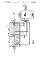
- FIG. 1 is a partially diagrammatic view of an embodiment of the present temperature measuring apparatus, including an enlarged transverse cross-sectional view of the reference bodies, which is adapted for detecting the temperature of a moving web;
- FIG. 2 is a diagrammatic view of the reference bodies of an embodiment of the invention whose surfaces are contoured to match the curvature of a moving roll;
- FIG. 3 is a perspective view of an embodiment of the temperature detection apparatus which is particularly adopted for detecting the temperature of fast moving elongated objects
- FIG. 4 is a partially diagrammatic view of the apparatus in FIG. 3, including an enlarged transverse cross-sectional view of the reference bodies;
- FIG. 5 is a view taken along the line 5--5 of FIG. 4.
- One feature of the present invention is the ability of the apparatus to measure the temperature of an object without physical contact. This feature arises from the recognition that the heat flow rate between a reference body and an external body is proportional to the temperature of the latter.
- the present invention also achieves autocalibration. It should be noted that while heat flow sensors manufactured from the same design and materials exhibit the same sensitivities, to practice the prevent invention it is not necessary to employ identical sensors but only heat flow sensors of the same sensitivity.
- the autocalibration aspect of the invention is based on the correlation between the external body temperature, the reference body temperatures, and the voltage generated by the heat flow sensors.
- ⁇ X distance of thermal path between product and sensor (identical for both sensors)
- E A voltage generated by heat flow sensor A and is proportional to Q A
- E B voltage generated by heat flow sensor B and is proportional to Q B
- T p temperature of external body or product
- T A temperature of reference body containing sensor A
- T B temperature of reference body containing sensor B
- the temperature of the external body or product can, according to the present invention, be expressed as: ##EQU2## wherein the temperature of the external body or product T p is expressed as a function of T A , T B , E A and E B only.
- the invention provides accurate measurements of these variables from which the temperature T p of the external body is calculated by the equation set forth above.
- the present invention is thus self-calibrating and insensitive to variations in the distance or conductivity of the spacing between an external body and the heat flow sensors.
- a micro-controller programmed to receive input signals corresponding to parameters T A , T B , E A and E B can be employed to calculate T p based on the above equation.
- a temperature detection apparatus 10 which comprises, generally, two thermally conductive reference bodies 12 and 14 separated by a thermal barrier 16; temperature change means for altering the temperature of reference body 12, including an electrical resistance heating element or cartridge 18; heat flow sensors 20 with the same sensitivity; and temperature sensors 22.
- the apparatus 10 is adapted to detect the temperature of any fixed surface external body including films, webs, and elongated elements.
- the temperature of web 24 is measured by placement of the reference bodies 12 and 14 in proximity to the web 24 without physically contacting the web.
- a web encompasses any continuous material including thin metal sheets, fabrics, strips, paper, or the like.
- the reference bodies 12 and 14 are thermally conductive reference bodies made of material such as anodized aluminum, nickel plated copper or the like, and each constitutes a thermal sink into and out of which heat flow can occur.
- the operative face 34 is located a distance from the web 24 whose temperature is to be measured.
- the web 24 moves along a path in close proximity to the heat flow sensor 20 and the operative face 34 of reference body 12.
- the first reference body 12 and the second reference body 14 are separated by a thermal barrier 16 that can consist of an air gap or any suitable non-heat-conductive material such as aramid paper.
- heat flow sensor 20 is the same distance from the web 24 as the heat flow sensor in the first reference body 12 is from the web.
- the distance between the web 24 and the heat flow sensors 20 afforded by this arrangement is approximately 0.030 to 0.125 inch, although of course, this will vary with product velocity and the attendant boundary layer thickness which will result from the particular application at hand.
- guides 36 can be employed to facilitate passage of the web across the heat flow sensors 20.
- the cartridge heater 18 may be any suitable heater for raising the temperature of the mass of reference body 12. Various other means could also be used for raising the temperature of the reference body 12, such as fluid heating passages provided therein. It should be noted that since the present invention requires only that the temperatures of the reference bodies 12 and 14 be different, cooling rather than heating one of the heads can be employed.
- heat flow sensor utilized is not critical to the present invention, so long as it is capable of sensing the convective heat flow resulting from a temperature differential between the web 24 and the mass of the reference bodies 12 and 14.
- the heat flow sensors 20 illustrated are thermoelectric devices or differential thermopiles adapted to generate voltages proportional to the rates of heat flow into or out of the surfaces on which they are mounted.
- Each operative face 34 may be provided with a thin thermally reflective coating 40, such as gold or aluminum, which is operative to reflect any extraneous radiant heat flow component through the web 24 or elsewhere, without affecting the larger and more significant convective-conductive heat flow components.
- a thin thermally reflective coating 40 such as gold or aluminum, which is operative to reflect any extraneous radiant heat flow component through the web 24 or elsewhere, without affecting the larger and more significant convective-conductive heat flow components.
- reflective coating is useful when the product to be measured is made of material that is transparent to radiation.
- the temperature sensor 22 is disposed within and in thermal exchange relation with the walls of a bore provided in reference body 12.
- a temperature sensor 22 is similarly situated in reference body 14.
- Each of the temperature sensors 22 is preferably a platinum RTD located relatively close to the operative faces 34.
- the temperature sensors 22 generate voltages proportional to their temperatures and could, if desired, also take the form of thermocouples or other means suitable for the purpose described.
- the output signals from the heat flow sensors 20 are applied through leads 50, in turn, to an analog to digital converter 52.
- the converter 52 is selected and operated such as to adjust the magnitude of the output signals from the heat flow sensors 20 to a convenient sensitivity in terms of the volts per heat flow rate per unit area.
- the voltage output signal form heat flow sensor 20 in reference body 12 is designated E A .
- E B denotes the voltage output signal from heat flow sensor 20 in reference body 14.
- Output signals from the temperature sensors 20 in reference bodies 12 and 14 are applied through leads 54, in turn, to the analog to digital converter 52.
- the signals from the temperature sensors 22 are converted to the temperatures of the reference bodies 12 and 14, denoted here as T A and T B , respectively.
- the signals from the converter 52 are applied to a micro-controller 88 where the temperature of the external body or product T p is calculated via the equation for T p described above; T p is displayed on temperature read-out 58.
- the micro-controller 88 can also be used to regulate the temperature T A of head 12 by controlling the amount of heating (or cooling) of that reference body 12 via a heat controller 60.
- the present invention is applicable regardless of the temperature scale used.
- FIG. 2 illustrates an embodiment of the present invention particularly suited for measuring the temperature of objects that have curved surfaces such as rolls used in rolling metal, calendering and laminating of sheet material and heating of textiles and drying in paper mills.
- apparatus 28 which consists, in part, of reference bodies 30 and 32 separated by barrier 42.
- the contour shape of the operative faces 44 and 46 is designed to coincide with the curvature of the roll in order that the distance between the roll 26 and heat flow sensor 48 be the same as the distance between the roll 26 and heat flow sensor 84.
- the description of the rest of the apparatus, not shown, including means for regulating the temperature of one reference body, temperature sensors and micro-controller, is the same as set forth previously.
- FIGS. 3, 4 and 5 show an embodiment of the present invention that is particularly suited for measuring the temperatures of wires, filaments or other elongated elements moving along their longitudinal axes.
- This preferred embodiment comprises generally an apparatus 62 with an aperture 64 of approximately 1/8 inch in diameter that runs through the length of the apparatus' 62 center.
- Apparatus 62 is shown as a cylindrical device but, as is apparent from the description hereinbelow, its outer configuration is unimportant. However, for ease of description, the cylindrical form will be used.
- the apparatus 62 comprises, generally, two thermally conductive reference bodies 56 and 66 that are separated by a thermal barrier 68; temperature change means for altering the temperature of the head; including an electrical resistance heating element 70; heat flow sensors 72; and temperature sensors 74. Except as further described, the hereinabove described components of the reference bodies 56 and 66 in this preferred embodiment are substantially the same as those found in the first-described apparatus 10 in FIG. 1 and their descriptions shall not be repeated.
- Guides 76 are annularly situated at the entrance 78 and exit 80 of the apparatus 62.
- the guides 76 which can be made of ceramic, form the only potential points of contact with the filament 82 and generate negligible frictional heat. It should be noted that the purpose of the guides 76 is to prevent filament 82 from touching the surface of the aperture 64 or any other part of the apparatus. The function of guides 76 is not to maintain the filament 82 at any particular location in the aperture 64. As will be apparent, apparatus 62 yields accurate temperature measurements regardless of the filament's position inside the aperture 64.
- each reference body 56 and 66 comprises a plurality of heat flow sensors 72 situated around the moving filament 82.
- each reference body 56 and 66 are four heat flow sensors 72, spaced approximately 90 degrees apart around the filament 82.
- the output signals from the four heat flow sensors 72 in each reference body 56 and 66 are applied through leads 50, in turn, to an analog to digital converter 52.
- output signals from the temperature sensors 74 from both reference bodies 56 and 66 are applied through leads 54, in turn, to the converter array 52.
- the converter array 52 adjusts the four output signals from each of the heat flow sensors 72 of each reference body 56 and 66 to a convenient sensitivity in terms of volts per heat flow unit per unit area.
- the signals from the temperature sensors 74 are converted to the temperatures of the reference bodies, i.e., T A and T B .
- the signals from the converter array 52 are applied to a micro-controller 54 where the temperature of the filament T p is calculated via the equation for T p described above; T p is displayed on temperature read-out 58.
- the micro-controller 88 can be used to regulate the temperature T A by controlling the amount of heating (or cooling) of that reference body 56 via a heat controller 60.
- heat flow sensor or temperature sensor utilized in the various embodiments herein described need only be capable of providing an output directly proportional to heat flow, in the case of a heat flow sensor, or directly proportional to the temperature of the head or probe, in the case of the temperature sensor. Also, as will be apparent, the apparatus can be used with a variety of process controllers.
- the temperature differences are at all times relatively small. That is, the temperature difference between the two reference bodies is in the order of 10° to 100° F.; moreover, the temperature differences between the reference bodies and the product is in the order of 0° to 100° F.
- the fluid layers between the faces and external body take on temperature distributions which are dependent upon the temperatures of the reference and external bodies only.
- the reference bodies serve to isolate the measuring operation from the effects of the ambient temperature conditions, whereby the heat flows to be measured are a function of the relative temperatures of the reference bodies and the external body.
Landscapes
- Physics & Mathematics (AREA)
- General Physics & Mathematics (AREA)
- Measuring Temperature Or Quantity Of Heat (AREA)
- Investigating Or Analyzing Materials Using Thermal Means (AREA)
Abstract
Description
Claims (10)
Priority Applications (5)
| Application Number | Priority Date | Filing Date | Title |
|---|---|---|---|
| US07/429,983 US5216625A (en) | 1989-11-01 | 1989-11-01 | Autocalibrating dual sensor non-contact temperature measuring device |
| EP90402783A EP0426517B1 (en) | 1989-11-01 | 1990-10-08 | Autocalibrating dual sensor non-contact temperature measuring device |
| DE90402783T DE69004784T2 (en) | 1989-11-01 | 1990-10-08 | Self-calibrating, contactless temperature device with a pair of sensors. |
| JP2281705A JPH0754272B2 (en) | 1989-11-01 | 1990-10-19 | Method and apparatus for auto-calibration vs. sensor non-contact temperature measurement |
| US07/859,819 US5294200A (en) | 1989-11-01 | 1992-03-30 | Autocalibrating dual sensor non-contact temperature measuring device |
Applications Claiming Priority (1)
| Application Number | Priority Date | Filing Date | Title |
|---|---|---|---|
| US07/429,983 US5216625A (en) | 1989-11-01 | 1989-11-01 | Autocalibrating dual sensor non-contact temperature measuring device |
Related Child Applications (1)
| Application Number | Title | Priority Date | Filing Date |
|---|---|---|---|
| US07/859,819 Continuation-In-Part US5294200A (en) | 1989-11-01 | 1992-03-30 | Autocalibrating dual sensor non-contact temperature measuring device |
Publications (1)
| Publication Number | Publication Date |
|---|---|
| US5216625A true US5216625A (en) | 1993-06-01 |
Family
ID=23705565
Family Applications (1)
| Application Number | Title | Priority Date | Filing Date |
|---|---|---|---|
| US07/429,983 Expired - Lifetime US5216625A (en) | 1989-11-01 | 1989-11-01 | Autocalibrating dual sensor non-contact temperature measuring device |
Country Status (4)
| Country | Link |
|---|---|
| US (1) | US5216625A (en) |
| EP (1) | EP0426517B1 (en) |
| JP (1) | JPH0754272B2 (en) |
| DE (1) | DE69004784T2 (en) |
Cited By (12)
| Publication number | Priority date | Publication date | Assignee | Title |
|---|---|---|---|---|
| WO1995027886A1 (en) * | 1994-04-06 | 1995-10-19 | Luxtron Corporation | Autocalibrating non-contact temperature measuring technique employing dual recessed heat flow sensors |
| US5921680A (en) * | 1994-11-19 | 1999-07-13 | Pleva Gmbh | Sensor for radiation pyrometric temperature measurement at high ambient temperature |
| US20020191675A1 (en) * | 2001-06-18 | 2002-12-19 | Omron Corporation | Electronic clinical thermometer |
| US20040141544A1 (en) * | 2002-12-11 | 2004-07-22 | Sam Paris | Filament temperature measuring device with fluid velocity and temperature compensator system |
| US20050209813A1 (en) * | 2004-03-16 | 2005-09-22 | Johnson Controls Technology Company | Temperature sensing device |
| US20070171958A1 (en) * | 2006-01-23 | 2007-07-26 | Anh Hoang | Electrical device measurement probes |
| CN100343640C (en) * | 2001-04-11 | 2007-10-17 | 欧姆龙健康医疗事业株式会社 | Electronic thermometer |
| EP2317148A1 (en) * | 2008-08-19 | 2011-05-04 | Edwards Japan Limited | Vacuum pump |
| US20180328796A1 (en) * | 2015-11-12 | 2018-11-15 | Denso Corporation | Diagnosis apparatus of assembly state |
| US10443876B2 (en) | 2015-02-06 | 2019-10-15 | Johnson Controls Technology Company | Thermostat with heat rise compensation based on wireless data transmission |
| WO2022235154A1 (en) | 2021-05-04 | 2022-11-10 | Hukseflux Holding B.V. | Thermal sensor, measurement system, and method of estimating an air temperature and/or a convective heat transfer coefficient |
| WO2022235153A1 (en) * | 2021-05-04 | 2022-11-10 | Hukseflux Holding B.V. | Thermal comfort measuring system |
Families Citing this family (6)
| Publication number | Priority date | Publication date | Assignee | Title |
|---|---|---|---|---|
| US5294200A (en) * | 1989-11-01 | 1994-03-15 | Luxtron Corporation | Autocalibrating dual sensor non-contact temperature measuring device |
| EP0631120A1 (en) * | 1993-06-23 | 1994-12-28 | B a r m a g AG | Device for the contactless temperature measurement of a moving elongated object |
| DE19857453B4 (en) * | 1998-12-12 | 2008-03-20 | Pfeiffer Vacuum Gmbh | Temperature monitoring on rotors of vacuum pumps |
| US6408651B1 (en) | 1999-12-30 | 2002-06-25 | Corning Incorporated | Method of manufacturing optical fibers using thermopiles to measure fiber energy |
| FR2811756B1 (en) * | 2000-07-11 | 2002-10-25 | Peugeot Citroen Automobiles Sa | METHOD AND DEVICE FOR MEASURING THE AIR TEMPERATURE IN A PREMISES, IN PARTICULAR IN A MOTOR VEHICLE INTERIOR |
| DE10063444A1 (en) * | 2000-12-20 | 2002-05-29 | Infineon Technologies Ag | Method for determining the temperature and power loss of a semiconductor body of a semiconductor component, using surface temperature measurements so that service life can be estimated |
Citations (14)
| Publication number | Priority date | Publication date | Assignee | Title |
|---|---|---|---|---|
| US2991654A (en) * | 1959-08-20 | 1961-07-11 | William E Engelhard | Device for measuring surface heat of moving members |
| US3111844A (en) * | 1959-12-23 | 1963-11-26 | Gen Electric | Heat rate measuring apparatus |
| US3427882A (en) * | 1965-04-05 | 1969-02-18 | Kleinewefers Soehne J | Contact-free temperature-sensing device |
| US3430492A (en) * | 1964-12-25 | 1969-03-04 | Teijin Ltd | Apparatus for measuring continuously the temperature of traveling yarn |
| US3475962A (en) * | 1967-09-07 | 1969-11-04 | United States Steel Corp | Apparatus for measuring strip temperature |
| US3525260A (en) * | 1966-12-20 | 1970-08-25 | Bbc Brown Boveri & Cie | Arrangement for contactless measurement of the temperature of a moving wire |
| US3542123A (en) * | 1968-06-17 | 1970-11-24 | David R Hornbaker | Temperature measurement apparatus |
| US3605490A (en) * | 1969-12-05 | 1971-09-20 | American Standard Inc | Heat sensor |
| US3715923A (en) * | 1970-07-23 | 1973-02-13 | D Rall | Temperature measuring method and apparatus |
| US3720103A (en) * | 1970-11-03 | 1973-03-13 | Cornell Aeronautical Labor Inc | Heat flux measuring system |
| US3926053A (en) * | 1972-08-22 | 1975-12-16 | Maschf Augsburg Nuernberg Ag | Apparatus for non-contact, accurate and continuous determination of surface temperature on a part |
| US4408903A (en) * | 1981-03-30 | 1983-10-11 | Southwire Company | Method of and apparatus for radiation pyrometric temperature measurement of a continuous cast metal bar |
| US4621615A (en) * | 1985-08-19 | 1986-11-11 | Mcgee Thomas D | Energy control device |
| US4906105A (en) * | 1985-11-20 | 1990-03-06 | United Biscuits (Uk) Limited | Measurement of thermal conditions |
Family Cites Families (3)
| Publication number | Priority date | Publication date | Assignee | Title |
|---|---|---|---|---|
| JPS5355085A (en) * | 1976-10-28 | 1978-05-19 | Mitsubishi Heavy Ind Ltd | Continous measuring method for temperatuer of high temperature materials |
| JPS588729B2 (en) * | 1980-11-11 | 1983-02-17 | 安立計器株式会社 | Temperature measuring part of non-contact surface thermometer |
| JPS5838824A (en) * | 1981-08-31 | 1983-03-07 | Yokogawa Hokushin Electric Corp | Temperature measuring system |
-
1989
- 1989-11-01 US US07/429,983 patent/US5216625A/en not_active Expired - Lifetime
-
1990
- 1990-10-08 EP EP90402783A patent/EP0426517B1/en not_active Expired - Lifetime
- 1990-10-08 DE DE90402783T patent/DE69004784T2/en not_active Expired - Fee Related
- 1990-10-19 JP JP2281705A patent/JPH0754272B2/en not_active Expired - Lifetime
Patent Citations (15)
| Publication number | Priority date | Publication date | Assignee | Title |
|---|---|---|---|---|
| US2991654A (en) * | 1959-08-20 | 1961-07-11 | William E Engelhard | Device for measuring surface heat of moving members |
| US3111844A (en) * | 1959-12-23 | 1963-11-26 | Gen Electric | Heat rate measuring apparatus |
| US3430492A (en) * | 1964-12-25 | 1969-03-04 | Teijin Ltd | Apparatus for measuring continuously the temperature of traveling yarn |
| DE1573346A1 (en) * | 1964-12-25 | 1969-05-22 | Teijin Ltd | Apparatus for continuous measurement of the temperature of running yarn |
| US3427882A (en) * | 1965-04-05 | 1969-02-18 | Kleinewefers Soehne J | Contact-free temperature-sensing device |
| US3525260A (en) * | 1966-12-20 | 1970-08-25 | Bbc Brown Boveri & Cie | Arrangement for contactless measurement of the temperature of a moving wire |
| US3475962A (en) * | 1967-09-07 | 1969-11-04 | United States Steel Corp | Apparatus for measuring strip temperature |
| US3542123A (en) * | 1968-06-17 | 1970-11-24 | David R Hornbaker | Temperature measurement apparatus |
| US3605490A (en) * | 1969-12-05 | 1971-09-20 | American Standard Inc | Heat sensor |
| US3715923A (en) * | 1970-07-23 | 1973-02-13 | D Rall | Temperature measuring method and apparatus |
| US3720103A (en) * | 1970-11-03 | 1973-03-13 | Cornell Aeronautical Labor Inc | Heat flux measuring system |
| US3926053A (en) * | 1972-08-22 | 1975-12-16 | Maschf Augsburg Nuernberg Ag | Apparatus for non-contact, accurate and continuous determination of surface temperature on a part |
| US4408903A (en) * | 1981-03-30 | 1983-10-11 | Southwire Company | Method of and apparatus for radiation pyrometric temperature measurement of a continuous cast metal bar |
| US4621615A (en) * | 1985-08-19 | 1986-11-11 | Mcgee Thomas D | Energy control device |
| US4906105A (en) * | 1985-11-20 | 1990-03-06 | United Biscuits (Uk) Limited | Measurement of thermal conditions |
Cited By (22)
| Publication number | Priority date | Publication date | Assignee | Title |
|---|---|---|---|---|
| US5464284A (en) * | 1994-04-06 | 1995-11-07 | Luxtron Corporation | Autocalibrating non-contact temperature measuring technique employing dual recessed heat flow sensors |
| WO1995027886A1 (en) * | 1994-04-06 | 1995-10-19 | Luxtron Corporation | Autocalibrating non-contact temperature measuring technique employing dual recessed heat flow sensors |
| US5921680A (en) * | 1994-11-19 | 1999-07-13 | Pleva Gmbh | Sensor for radiation pyrometric temperature measurement at high ambient temperature |
| CN100343640C (en) * | 2001-04-11 | 2007-10-17 | 欧姆龙健康医疗事业株式会社 | Electronic thermometer |
| US20020191675A1 (en) * | 2001-06-18 | 2002-12-19 | Omron Corporation | Electronic clinical thermometer |
| US6886978B2 (en) * | 2001-06-18 | 2005-05-03 | Omron Corporation | Electronic clinical thermometer |
| US20040141544A1 (en) * | 2002-12-11 | 2004-07-22 | Sam Paris | Filament temperature measuring device with fluid velocity and temperature compensator system |
| US7395173B2 (en) * | 2004-03-16 | 2008-07-01 | Johnson Controls Technology Company | Temperature sensing device |
| US20060074586A1 (en) * | 2004-03-16 | 2006-04-06 | Johnson Controls Technology Company | Temperature sensing device |
| US20050209813A1 (en) * | 2004-03-16 | 2005-09-22 | Johnson Controls Technology Company | Temperature sensing device |
| US20080298431A1 (en) * | 2004-03-16 | 2008-12-04 | Johnson Controls Technology Company | Temperature sensor |
| US7785004B2 (en) | 2004-03-16 | 2010-08-31 | Johnson Controls Technology Company | Temperature sensor |
| US20070171958A1 (en) * | 2006-01-23 | 2007-07-26 | Anh Hoang | Electrical device measurement probes |
| EP2317148A4 (en) * | 2008-08-19 | 2015-03-25 | Edwards Japan Ltd | Vacuum pump |
| EP2317148A1 (en) * | 2008-08-19 | 2011-05-04 | Edwards Japan Limited | Vacuum pump |
| US10443876B2 (en) | 2015-02-06 | 2019-10-15 | Johnson Controls Technology Company | Thermostat with heat rise compensation based on wireless data transmission |
| US20180328796A1 (en) * | 2015-11-12 | 2018-11-15 | Denso Corporation | Diagnosis apparatus of assembly state |
| US10845256B2 (en) * | 2015-11-12 | 2020-11-24 | Denso Corporation | Diagnosis apparatus of assembly state |
| WO2022235154A1 (en) | 2021-05-04 | 2022-11-10 | Hukseflux Holding B.V. | Thermal sensor, measurement system, and method of estimating an air temperature and/or a convective heat transfer coefficient |
| NL2028140B1 (en) | 2021-05-04 | 2022-11-10 | Hukseflux Holding B V | Thermal sensor and measurement system |
| WO2022235153A1 (en) * | 2021-05-04 | 2022-11-10 | Hukseflux Holding B.V. | Thermal comfort measuring system |
| NL2028142B1 (en) * | 2021-05-04 | 2022-11-23 | Hukseflux Holding B V | Thermal comfort measuring system |
Also Published As
| Publication number | Publication date |
|---|---|
| DE69004784D1 (en) | 1994-01-05 |
| JPH0754272B2 (en) | 1995-06-07 |
| DE69004784T2 (en) | 1994-03-17 |
| EP0426517B1 (en) | 1993-11-24 |
| JPH03148026A (en) | 1991-06-24 |
| EP0426517A1 (en) | 1991-05-08 |
Similar Documents
| Publication | Publication Date | Title |
|---|---|---|
| US5216625A (en) | Autocalibrating dual sensor non-contact temperature measuring device | |
| US5294200A (en) | Autocalibrating dual sensor non-contact temperature measuring device | |
| US3715923A (en) | Temperature measuring method and apparatus | |
| Ashauer et al. | Thermal flow sensor for liquids and gases based on combinations of two principles | |
| US8561461B2 (en) | Calorimetric flow meter having high heat conductivity strips | |
| US3525260A (en) | Arrangement for contactless measurement of the temperature of a moving wire | |
| US4989970A (en) | Non-contact sensing apparatus and method for temperature profile and thickness determination and control of radiation translucent materials | |
| US3542123A (en) | Temperature measurement apparatus | |
| Shibata et al. | New laser-flash method for measuring thermal diffusivity of isotropic and anisotropic thin films | |
| US5452601A (en) | Method for simultaneous determination of thermal conductivity and kinematic viscosity | |
| US3285069A (en) | Instrument for measuring temperature of extended surfaces | |
| JP3328408B2 (en) | Surface temperature measurement method | |
| Gaviot et al. | Thin foil planar radiometers: application for designing contactless sensors | |
| JPS5923369B2 (en) | Zero-level heat flow meter | |
| US6382024B1 (en) | Thermocouple boundary layer rake | |
| JPH02255219A (en) | Measuring device for plate temperature in plate rolling | |
| Chanetz et al. | Characterisation of Flow Properties at the Surface | |
| SU693198A1 (en) | Calorimeter for measuring specific heat and thermal effects | |
| JPH0427496B2 (en) | ||
| SU348855A1 (en) | THE ETHRICAL DEVICE FOR IZL \ ERE1 LINEAR VALUES OF PRODUCTS f {ib..t ^ iyf2ij -. 'I> &;; •. "? ISHUTEKA | |
| Godts et al. | A new self calibrating radiation planar microsensor. Application to contactless temperature measurement | |
| SU502242A1 (en) | Device for measuring unsteady heat fluxes | |
| JPH0516730B2 (en) | ||
| RU2093801C1 (en) | Two-junction temperature transmitter | |
| White et al. | Thermographic techniques for arc-jet testing |
Legal Events
| Date | Code | Title | Description |
|---|---|---|---|
| AS | Assignment |
Owner name: LUXTRON CORPORATION, CALIFORNIA Free format text: ASSIGNMENT OF ASSIGNORS INTEREST.;ASSIGNOR:RALL, DIETER L.;REEL/FRAME:005170/0541 Effective date: 19891031 |
|
| STCF | Information on status: patent grant |
Free format text: PATENTED CASE |
|
| CC | Certificate of correction | ||
| FPAY | Fee payment |
Year of fee payment: 4 |
|
| FEPP | Fee payment procedure |
Free format text: PAYOR NUMBER ASSIGNED (ORIGINAL EVENT CODE: ASPN); ENTITY STATUS OF PATENT OWNER: LARGE ENTITY |
|
| REMI | Maintenance fee reminder mailed | ||
| FPAY | Fee payment |
Year of fee payment: 8 |
|
| SULP | Surcharge for late payment |
Year of fee payment: 7 |
|
| AS | Assignment |
Owner name: IRCON, INC., ILLINOIS Free format text: ASSIGNMENT OF ASSIGNORS INTEREST;ASSIGNOR:LUXTRON CORPORATION;REEL/FRAME:014162/0317 Effective date: 20030530 |
|
| FPAY | Fee payment |
Year of fee payment: 12 |
|
| AS | Assignment |
Owner name: COMERICA BANK, CALIFORNIA Free format text: SECURITY AGREEMENT;ASSIGNOR:LUXTRON CORPORATION;REEL/FRAME:019224/0843 Effective date: 20070412 |
|
| AS | Assignment |
Owner name: FLUKE CORPORATION, WASHINGTON Free format text: ASSIGNMENT OF ASSIGNORS INTEREST;ASSIGNOR:IRCON, INC.;REEL/FRAME:021561/0582 Effective date: 20080714 |
|
| AS | Assignment |
Owner name: LUMASENSE TECHNOLOGIES HOLDINGS, INC., CALIFORNIA Free format text: RELEASE BY SECURED PARTY;ASSIGNOR:COMERICA BANK, N.A.;REEL/FRAME:047567/0134 Effective date: 20180904 |