US5199017A - Optical disk drive and method for counting the number of tracks on an optical disk - Google Patents
Optical disk drive and method for counting the number of tracks on an optical disk Download PDFInfo
- Publication number
- US5199017A US5199017A US07/757,775 US75777591A US5199017A US 5199017 A US5199017 A US 5199017A US 75777591 A US75777591 A US 75777591A US 5199017 A US5199017 A US 5199017A
- Authority
- US
- United States
- Prior art keywords
- tes
- pulse
- generating
- level
- negative
- Prior art date
- Legal status (The legal status is an assumption and is not a legal conclusion. Google has not performed a legal analysis and makes no representation as to the accuracy of the status listed.)
- Ceased
Links
Images


Classifications
-
- G—PHYSICS
- G11—INFORMATION STORAGE
- G11B—INFORMATION STORAGE BASED ON RELATIVE MOVEMENT BETWEEN RECORD CARRIER AND TRANSDUCER
- G11B7/00—Recording or reproducing by optical means, e.g. recording using a thermal beam of optical radiation by modifying optical properties or the physical structure, reproducing using an optical beam at lower power by sensing optical properties; Record carriers therefor
- G11B7/08—Disposition or mounting of heads or light sources relatively to record carriers
- G11B7/085—Disposition or mounting of heads or light sources relatively to record carriers with provision for moving the light beam into, or out of, its operative position or across tracks, otherwise than during the transducing operation, e.g. for adjustment or preliminary positioning or track change or selection
- G11B7/08505—Methods for track change, selection or preliminary positioning by moving the head
- G11B7/08541—Methods for track change, selection or preliminary positioning by moving the head involving track counting to determine position
Definitions
- This invention relates to an optical disk drive, and is particularly concerned with a method for counting the number of tracks an optical head crosses during a seek operation in an optical disk drive.
- Optical structures to generate a TES are grouped into several classes, such as a push-pull method, a three-beam method, etc.
- a TES in any method is a signal of a waveform showing that a positive peak and a negative peak occur alternately each time a laser beam crosses a land part 110 and a groove part 120 of an optical disk 100, as shown in FIG. 12A.
- the TES is at a zero level when a laser beam passes through the land center 110A of the land part 110 and the groove center 120A of the groove part 120.
- FIG. 13 shows an example of conventional circuit structure to count the number of tracks an optical head crosses, based on a TES described above.
- a window comparator 131 as shown in FIG. 14, generates a zero cross pulse if a TES is within a predetermined range of the zero level and a track count logic 133 counts the number of zero cross pulses.
- the positional information of a data recording part is usually written immediately before the data recording part in a pre-pitted form.
- Such positional information is called pre-pitted positional information and a pre-pitted portion thus obtained or a defect portion on the optical disk 100 causes noise within the TES when a laser beam crosses the pre-pitted portion or the defect portion.
- the above conventional circuit structure is apt to err in counting the number of tracks.
- FIG. 15 shows the trajectory of a laser beam during a low-velocity seek operation.
- a defect portion 150 usually spans more than one track on the recording surface of the optical disk 100. Accordingly, if the seek velocity is low, a laser beam passes through the defect portion 150 while the laser beam passes through one land part 110 and one groove part 120. This causes significant noise within the TES, as shown in FIG. 16. Said noise thus generated causes a pulse and frequently count errors in counting the number of tracks by the track count logic 133. The same problem is also caused if a laser beam passes through a pre-pitted portion. Further, other noises are apt to cause counting errors.
- the principal object of this invention is to ensure that the number of tracks is precisely counted even if a defect portion or a pre-pitted portion which causes noise is on the recording surface of an optical disk, of if noise is caused by other sources.
- the invention is a positive peak level comparator for generating a positive peak pulse when a TES (Tracking Error Signal) is higher than a predetermined positive level, a negative peak level comparator for generating a negative peak pulse when the TES is lower than a predetermined negative level, and a logic circuit for generating an output pulse when said positive peak pulse and said negative peak pulse have been alternately input thereto.
- the arrangement prevents the TES from being miscounted even if the TES is disturbed due to the occurrence of, for example, a noise at a level close to either said predetermined positive level or said predetermined negative level and either said peak pulse or said negative pulse is successively generated.
- the invention also includes a filter circuit for passing said tracking error signal of high frequency (generated during a high-velocity seek operation) with high gain and, on the other hand, passing said tracking error signal of low frequency (generated during a low-velocity seek operation) with low gain, a positive peak level comparator for generating a positive peak pulse when the output signal from said filter circuit is higher than a predetermined positive level, a negative peak level comparator for generating a negative peak pulse when the output signal from said filter circuit is lower than a predetermined negative level, and a logic circuit for generating an output pulse when said positive peak pulse and said negative peak pulse have been alternately input, to prevent the TES from being miscounted by the decrease of the amplitude of TES which is apt to be caused if a laser beam crosses a defect portion on the disk during a high-velocity seek operation.
- the invention also includes a first positive peak level comparator for generating a positive peak pulse when said tracking error signal is higher than a predetermined first positive level, a first negative peak level comparator for generating a negative peak pulse when said tracking error signal is lower than a predetermined first negative level, a second positive peak level comparator for generating a positive peak pulse when said tracking error signal is higher than a predetermined second positive level lower than said predetermined first positive level, a second negative peak level comparator for generating a negative peak pulse when said tracking error signal is lower than a predetermined second negative level higher than said predetermined first negative level, and a logic circuit for generating an output pulse when said positive peak pulse and said negative peak pulse have been alternately input from said first positive peak level comparator and said first negative peak level comparator, respectively, during a low-velocity seek operation, and for generating an output pulse when said positive peak pulse and said negative peak pulse have been alternately input from said second positive peak level comparator and said second negative peak level comparator, respectively, during a high-velocity seek
- the invention also includes a window comparator for generating a zero cross pulse when said tracking error signal is within a predetermined range including a zero level, a positive peak level comparator for generating a positive peak pulse when said tracking error signal is higher than a predetermined positive level, a negative peak level comparator for generating a negative peak pulse when said tracking error signal is lower than a predetermined negative level, and a logic circuit for generating an output pulse when said zero cross pulse, said positive peak pulse, and said negative peak pulse have been input in predetermined order, to prevent the TES from being miscounted even if the TES is disturbed by the occurrence of, for example, a noise at a level close to either said predetermined positive level or said predetermined negative level and either said peak pulse or said negative pulse is successively generated, or the TES is disturbed for the reason why said predetermined range including the zero level is exceeded.
- the invention also includes a window comparator for generating a zero cross pulse when said tracking error signal is within a predetermined range including a zero level, a positive peak level comparator for generating a positive peak pulse when said tracking error signal is higher then a predetermined positive level, a negative peak level comparator for generating a negative peak pulse when said tracking error signal is lower than a predetermined negative level, and a logic circuit for generating an output pulse when said positive peak pulse and said negative peak pulse have been alternately input from said positive peak level comparator and said negative peak level comparator, respectively, during a low-velocity seek operation and generating an output pulse when a zero cross pulse has been input from said window comparator during a high-velocity seek operation, to eliminate the effect of a noise caused by a defect portion, etc. with no use of said window comparator for generating said zero cross pulse if a seek operation is performed at a low velocity.
- the invention also includes a window comparator for generating a zero cross pulse when said tracking error signal is within a predetermined range including a zero level, a filter circuit for passing said tracking error signal of high frequency with high gain and, on the other hand, passing said tracking error signal of low frequency with low gain, a positive peak level comparator for generating a positive peak pulse when an output signal from said filter circuit is higher than a predetermined positive level, a negative peak level comparator for generating a negative peak pulse when an output signal from said filter circuit is lower than a predetermined negative level, and a logic circuit for generating an output pulse when said zero cross pulse, said positive peak pulse, and said negative peak pulse have been input in predetermined order, to relatively amplify the amplitude of TES in said filter circuit so as to decrease the effect of the decrease of the amplitude of TES which is apt to extend during a high-velocity seek operation.
- the invention also includes a window comparator for generating a zero cross pulse when said tracking error signal is within a predetermined range including a zero level, a pulse discriminator for generating a discriminated zero cross pulse in response to said zero cross pulse whose time width is greater than or equal to a predetermined value, a filer circuit for passing said tracking error signal of said high frequency with high gain and, on the other hand, passing said TES of said low frequency with low gain, a positive peak level comparator for generating a positive peak pulse when an output signal from said filer circuit is higher than a predetermined positive level, a negative peak level comparator for generating a negative peak pulse when an output signal from said filter circuit is lower than a predetermined negative level, and a logic circuit for generating an output pulse when said discriminated zero cross pulse, said positive peak pulse, and said negative peak pulse have been input in predetermined order during a low-velocity seek operation.
- a window comparator for generating a zero cross pulse when said tracking error signal is within a predetermined range including a
- the arrangement generates an output pulse when said positive peak pulse and said negative peak pulse have been alternately input during a high-velocity seek operation, to decrease or increase a level detected by the level comparators which detect a positive peak and a negative peak of TES if the seek operation of the optical head is at a high or low velocity, respectively, by the filters placed ahead of the level comparator, in which the more frequency becomes low, gain decreases, and prevents tracks from being miscounted by the decrease of the amplitude of TES due to disturbance during a period of high seek velocity and by a noise within TES during a period of low seek velocity, by the pulse discriminator preceded by the window comparator detecting a zero cross of TES, in which a pulse with short time width is not regarded as a pulse.
- FIG. 1 is a block diagram showing a part of an embodiment of an optical disk drive according to the invention.
- FIG. 2 is a perspective view showing another part of said embodiment.
- FIG. 3 is a graph showing a velocity profile of said embodiment.
- FIG. 4 is a ground plane showing the trajectory of a laser beam on an optical disk during a high-velocity seek operation.
- FIGS. 5(A)-(D) shows charts showing the waveforms of a TES, a TES which has passed through a high-pass filter, a positive peak pulse, and a negative peak pulse during a high-velocity seek operation.
- FIGS. 6(A)-(B) shows charts of the waveforms of a TES, a zero cross pulse, a discriminated zero cross pulse, a positive peak pulse, and a negative peak pulse during a low-velocity seek operation.
- FIG. 7 to FIG. 11 are block diagrams showing alternative embodiments.
- FIGS. 12(A)-(C) shows charts of the waveforms of a TES and a TCS with respect to the structure of an optical disk.
- FIG. 13 is a block diagram showing the structure of a conventional track number counting means.
- FIG. 14(A) and (B) shows waveform charts representing the fundamentals of operations in said conventional track number counting means.
- FIG. 15 is a ground place showing the trajectory of a laser beam on an optical disk during a low-velocity seek operation.
- FIG. 16(A) and (B) shows waveform charts representing a failure in counting the number of tracks in said conventional track number counting means.
- FIG. 2 shows a part of an embodiment of an optical disk drive according to the invention.
- an optical head 10 is composed of a coarse actuator 20 and a fine actuator 30.
- the coarse actuator 20 is supported by a rail 22 so that it can move freely in the radial direction of an optical disk 100 (in the direction of a seek operation), and is driven in the direction of the seek operation by a coarse actuator VCM (Voice Coil Motor) 24.
- VCM Vehicle Coil Motor
- the fine actuator 30 is supported by the coarse actuator 20 through a shaft 32 so that it can move in the focusing and tracking directions and is driven in the focusing direction and in the tracking direction by a focus VCM 34 and a tracking VCM 36, respectively.
- the fine actuator 30 has a fixed objective lens 38 which a laser beam 40 is projected onto optical disk 100.
- coarse actuator 20 is provided with a relative position error (RPE) detecting sensor 25, a focus error signal (FES) detecting sensor 27, and a tracking error signal (TES) detecting sensor 29.
- the relative position error (RPE) detecting sensor 25 is, for example, a photo sensor with two split sensitive parts to detect the quantity of a relative deflection (rotational deflection from a neutral position) of the fine actuator 30 from the coarse actuator 20.
- the focus error signal (FES) detecting sensor 27 is, for example, a photo sensor with four split sensitive parts to detect a positional difference of a spot of the laser beam 40 from a focusing point on the optical disk 100.
- the tracking error signal (TES) detecting sensor 29 is, for example, a photo sensor with two split sensitive parts to detect a positional difference of a spot of laser beam 40 from the center of a track on the optical disk 100.
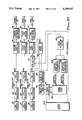
- FIG. 1 shows another part of said embodiment.
- an output of the relative position error (RPE) detecting sensor 25 is input to a RPE calculator 52.
- the RPE calculator 52 if the RPE detecting sensor 25 is a photo sensor with two split sensitive parts, calculates the difference between detecting signals from the two photo-sensitive parts and then outputs an unadjusted or a raw RPE.
- a RPE adjuster 54 When the gain or offset of unadjusted RPE is adjusted to a RPE adjuster 54, an adjusted RPE can be obtained and the adjusted RPE thus obtained is provided to a coarse servo controller 56 and a tracking servo controller 76.
- the RPE to which low-pass filtering and compensation for phase lead have been applied by the coarse servo controller 56, is provided to a coarse actuator VCM driver 58 from which the driving current, according to the amplitude and sign of the RPE, that is, the quantity and direction of a deflection of the fine actuator 30 relative to the coarse actuator 20, is provided to the coarse actuator VCM 24.
- An output of the FES detection sensor 27 is input to a FES calculator 62.
- the FES calculator 62 if the FES detecting sensor 27 is a photo sensor with four split sensitive parts, calculates the difference between a sum of detecting signals from a pair of photo sensitive parts and a sum of detecting signals from another pair of photo-sensitive parts and then outputs an unadjusted or a raw FES.
- a FES adjuster 64 When the offset of the unadjusted FES is adjusted by a FES adjuster 64, an adjusted FES can be obtained.
- the FES thus obtained is provided to a focus servo controller 66.
- the FES which low-pass filtering and compensation for phase lead have been applied by the focus servo controller 66, is provided to a focus VCM drive 68 from which the driving current, according to the amplitude and sign of the FES, that is, a positional difference and direction of a spot of the laser beam 40 from the focus point, is provided to the focus VCM 34.
- An output of the TES detecting sensor 29 is input to a TES calculator 72.
- the TES calculator if the TES detecting sensor 29 is a photo sensor with two split sensitive parts, calculates the difference between detecting signals from a pair of photo sensitive parts and outputs an unadjusted or a raw TES.
- the gain and offset of the unadjusted TES are adjusted by the TES adjuster 74, an adjusted TES can be obtained and provided to the tracking servo controller 76, a tracking VCM driver 78 providing a driving signal for tracking to the tracking VCM 36.
- the adjusted TES is also input to a window comparator 300 for zero cross detection in which a TES is checked to see whether the TES is within a predetermined range including an electric reference level (zero level). A zero cross pulse is output if the TES is within said range and a zero cross pulse is not generated if the TES is not within said range.
- the window comparator 300 is used to detect whether the TES has crossed said zero level.
- the zero cross pulse is input to a pulse discriminator 301, a digital low-pass filter which outputs only a pulse with a time width greater than or equal to a predetermined value within zero cross pulses.
- the pulse outputted from the pulse discriminator 301 is called hereafter a discriminated zero cross pulse.
- the discriminated zero cross pulse is inputted to a track count logic 500 which is a logic circuit that generates an output pulse, or counts the number of tracks only if predetermined pulses are input in predetermined order.
- the adjusted TES is input to a filter circuit (peak detecting filer) 400.
- the filter circuit 400 is a high-pass filter for passing the TES of high frequency with high gain and passing the TES of low frequency with low gain.
- the filter circuit 400 is a filter having an amplitude of TES during a low-velocity seek operation is smaller than the amplitude of TES during a high-velocity seek operation.
- An output signal from the filter circuit 400 is called hereafter a peak detection track cross signal to distinguish the output signal from the TES.
- the peak detection track cross signal is input to a positive peak level comparator 401 in which the peak detection track cross signal is compared with a constant value approaching a positive peak and changes to a positive peak pulse whose state changes near the appropriate level, and, at the same time, is input to a negative peak level comparator 402 in which the peak detection track cross signal is compared with a constant value approaching a negative peak and change to a negative peak pulse whose state changes near the appropriate level.
- the positive peak pulse and the negative peak pulse output from positive peak level comparator 401 and negative peak level comparator 402, respectively, are input to track count logic 500.
- the track count logic 500 functions in two types of count operation modes, high-velocity mode and low-velocity mode.
- high-velocity mode an output pulse is generated if the positive peak pulse and the negative peak pulse have been alternately input and, on the other hand, in low-velocity mode, an output pulse is generated if the positive peak pulse, the discriminated zero cross pulse, and the negative peak pulse have been input in this order.
- low-velocity mode an output pulse is generated if the positive peak pulse, the discriminated zero cross pulse, and the negative peak pulse have been input in this order.
- the track count logic 500 outputs an pulse, the content of a track counter 84 is decreased by one. Accordingly, the track counter 84 is decreased when the positive peak pulse changes to the negative peak pulse and vice versa in high-velocity mode and is discriminated zero cross pulse changes in the predetermined order in low-velocity mode.
- a change of track count logic 500 from high-velocity mode to low-velocity mode and vice versa takes place by means of a servo system controller (CPU and logic circuit) 200.
- the controller 200 can determine whether a current seek velocity is high or low, based on positional information as well as velocity information obtained from the TES, or the content of track counter 84.
- the seek velocity can be determined based on the content of track counter 84 since the relationship between the seek velocity and the number of tracks is indicated by a velocity profile ROM 86 so far as a seek velocity is under the control of the velocity profile ROM 86.
- the controller 200 is provided with the velocity profile ROM 86 in which information used for controlling the seek velocity, for example, the relation between a track distance from a current position to a target position and a desirable velocity, as in FIG. 3, used for controlling the seek velocity is stored.
- the velocity profile ROM 86 outputs a desirable velocity, represented as a digital value, at the current position to a velocity profile generator 88 in which the digital value is converted to an analog value to output the analog value to a seek block 90.
- the seek block 90 compares the value obtained from the velocity profile generator 88 with the current velocity information conveyed by the TES to product a positioning error signal (PES) which is an integrated value of the result of the comparison.
- PES positioning error signal
- the PES is provided to a selector 92 to which the TES as well as the PES is provided.
- the selector 92 provides the PES to the fine servo controller 76 and, on the other hand, in tracking operation mode, the selector 92 provides the TES to the fine tracking servo controller 76.
- the selector 92 may provide PES to not only the fine tracking servo controller 76 but the coarse servo controller 56.
- FIG. 4 shows the trajectory of a laser beam on the optical disk 100 during a high-velocity seek operation. If a seek operation is performed at a high-velocity, a laser beam crosses more than one track over a defect portion 150. As the result of the effect due to the defect portion 150 on the TES during such a high-velocity seek operation, the amplitude of TES decreases while the laser beam moves through the defect portion 150. If the TES (whose amplitude has decreased) is input, as it is, to the level comparators 401 and 402, the amplitude of TES does not reach the reference levels of the level comparators 401 and 402 and the positive and negative peak pulses cannot be detected.
- the TES (whose amplitude has decreased) is relatively amplified only during a high-velocity seek operation by the filter circuit 400 before inputting the TES to the level comparators 401 and 402, so as to be able to detect the positive and negative peak pulses.
- the amplitude of TES is relatively amplified only during a high-velocity seek operation, since the effect due to the defective portion 150 on the TES appears as a decrease in the amplitude of TES only during the high-velocity seek operation.
- the amplitude of TES during a low-velocity seek operation results in a decrease in the reference levels of the level comparators 401 and 402 and as a result of the decrease in the reference levels, extra undesired noises, which are apt to generate a peak and negative pulses, are picked up.
- the content of the track counter 84 is decreased only when a positive peak pulse and a negative peak pulse have been alternately generated.
- the track count logic 500 may decrease the content of the track counter 84 in response to the discriminated zero cross pulse.
- the track count logic 500 decreases the content of the track counter 84 in response to the generation of three types of pulses, a positive peak pulse, a negative peak pulse, and a discriminated zero cross pulse, in a predetermined order by means of the level comparators 401 and 402.
- the pulse discriminated 301 is used only during the low-velocity seek operation since if the pulse discriminator 301 is used when the high-velocity seek operation, during which the RES of high frequency is generated, is performed, the window comparator 300 generates only a pulse with short time width and an output from the pulse discriminator 301 remains a zero level.
- the number of tracks from a seek start position to a target position 0 is stored in the track counter 84 and the stored value is decreased by subtraction for each track crossing during the seek operation.
- a seek velocity is determined based on the value stored in the track counter 84 by reference to velocity profile (FIG. 3) in the velocity profile ROM 86.
- the seek operation is performed at a high velocity.
- said track count means are in high-velocity mode in which a count is made based on transition in the states of a positive peak pulse and a negative peak pulse. If the controller 200 detects that the value contained in the track counter 84 is a predetermined value at a time when the seek operation is nearly completed, the controller 200 changes said tack count means from high-velocity mode to low-velocity mode in which a count is made based on transition in the states of a positive peak pulse, a negative peak pulse, and a discriminated zero cross pulse.
- the detection levels of a positive peak and a negative peak are equivalently decreased during the high-velocity seek operation and, on the other hand, the detection levels of the positive peak and the negative peak are increased during the low-velocity seek operation to always generate proper positive and negative pulses. Further, the pulse discriminator 301 generates a zero cross pulse independent of noise.
- a pulse with short time width caused by noise can be removed by the pulse discriminator 301, however, it will be recognized that the noise may be removed directly from the TES by placing the low-pass filter ahead of the window comparator 300 instead of using the pulse discriminator 301.
- the number of tracks may be counted based on a zero cross pulse or three types of pulses, a zero cross pulse, a positive peak pulse, and a negative peak pulse, during the high-velocity seek operation and based on two types of pulses, a positive peak pulse and a negative peak pulse during the low-velocity seek operation.
- the number of tracks may be counted based on a zero cross pulse during the high-velocity seek operation and based on a positive peak pulse and a negative peak pulse during the low-velocity seek operation.
- the first positive peak level comparator 421 generates a positive peak pulse when the TES is above a predetermined first positive level
- the first negative peak level comparator 422 generates a negative peak pulse when the TES is below a predetermined first negative level
- the second positive peak level comparator 431 generates a positive peak pulse when the TES is above a predetermined second positive level lower than said predetermined first positive level
- the second negative peak level comparator 432 generates a negative peak pulse when the TES is below a predetermined second negative level higher than said predetermined first negative level being used.
- the number of tracks may be counted during a low-velocity seek operation if said positive peak pulse and said negative peak pulse have been alternately input from said first positive peak level comparator 421 and negative peak level comparator 422, respectively and, on the other hand, the number of tracks may be counted during a high-velocity seek operation if said positive peak pulse and negative peak pulse have been alternately input from said second positive peak level comparator 431 and negative peak level comparator 432, respectively.
- the filter circuit 400 may be varied according to seek velocity information or a stored value in the track counter 84.
- the number of tracks may be counted, as shown in FIG. 10, based on two types of pulses, a positive peak pulse and a negative peak pulse whether the seek operation is performed at a high velocity or a low velocity and further, as shown in FIG. 11, without using the filter circuit 40.
- a TES indicating the deviation of a beam from the center of a track in the radial direction of the disk has been described as a TES shown in FIG. 12(B).
- a signal shown in FIG. 12(C) may be used as a signal indicating the deviation.
- the signal shown in FIG. 12(C) is sometimes called a TCS (Track Cross Signal).
- TCS Track Cross Signal
Abstract
Description
Claims (10)
Priority Applications (2)
| Application Number | Priority Date | Filing Date | Title |
|---|---|---|---|
| US07/757,775 US5199017A (en) | 1991-09-11 | 1991-09-11 | Optical disk drive and method for counting the number of tracks on an optical disk |
| US08/430,947 USRE36864E (en) | 1990-09-27 | 1995-04-28 | Optical disk drive and methods for counting the number of tracks on an optical disk |
Applications Claiming Priority (1)
| Application Number | Priority Date | Filing Date | Title |
|---|---|---|---|
| US07/757,775 US5199017A (en) | 1991-09-11 | 1991-09-11 | Optical disk drive and method for counting the number of tracks on an optical disk |
Related Child Applications (1)
| Application Number | Title | Priority Date | Filing Date |
|---|---|---|---|
| US08/430,947 Reissue USRE36864E (en) | 1990-09-27 | 1995-04-28 | Optical disk drive and methods for counting the number of tracks on an optical disk |
Publications (1)
| Publication Number | Publication Date |
|---|---|
| US5199017A true US5199017A (en) | 1993-03-30 |
Family
ID=25049172
Family Applications (1)
| Application Number | Title | Priority Date | Filing Date |
|---|---|---|---|
| US07/757,775 Ceased US5199017A (en) | 1990-09-27 | 1991-09-11 | Optical disk drive and method for counting the number of tracks on an optical disk |
Country Status (1)
| Country | Link |
|---|---|
| US (1) | US5199017A (en) |
Cited By (24)
| Publication number | Priority date | Publication date | Assignee | Title |
|---|---|---|---|---|
| US5543697A (en) * | 1994-10-27 | 1996-08-06 | Sgs-Thomson Microelectronics, Inc. | Circuit and method for controlling the speed of a motor |
| US5581527A (en) * | 1991-10-09 | 1996-12-03 | Nippon Conlux Co., Ltd. | Information recording/reproducing apparatus for optical information recording medium using a track traverse detecting signal |
| US5610487A (en) * | 1994-05-19 | 1997-03-11 | Maxtor Corporation | Servo system with once per revolution rejection |
| US5627805A (en) * | 1995-11-15 | 1997-05-06 | Zen Research N.V. | Methods and apparatus for high speed optical storage device |
| US5652746A (en) * | 1995-11-15 | 1997-07-29 | Zen Research N.V. | Electronic track detection methods for apparatus for simultaneously reading multiple adjacent tracks of an optical disk |
| EP0806766A1 (en) * | 1996-05-09 | 1997-11-12 | Samsung Electronics Co., Ltd. | Track cross signal correction apparatus |
| US5701283A (en) * | 1995-11-15 | 1997-12-23 | Zen Research N.V. | Method and apparatus for high speed optical storage device |
| US5793715A (en) * | 1995-11-15 | 1998-08-11 | Zen Research N.V. | Methods and apparatus for reducing the access time of an optical drive |
| US5793549A (en) * | 1995-11-15 | 1998-08-11 | Zen Research N.V. | Methods and apparatus for synchronizing read out of data from multiple tracks of an optical storage device |
| US5802025A (en) * | 1995-11-15 | 1998-09-01 | Zen Research N.V. | Track detection methods and apparatus for simultaneous monitoring of multiple adjacent tracks of an optical disk |
| DE19743935A1 (en) * | 1997-10-04 | 1999-04-08 | Thomson Brandt Gmbh | Device for reading or writing to optical recording media |
| US5907526A (en) * | 1995-11-15 | 1999-05-25 | Zen Research N.V. | Methods and apparatus for simultaneously reading multiple tracks of an optical storage medium |
| US5914922A (en) * | 1997-12-12 | 1999-06-22 | Cirrus Logic, Inc. | Generating a quadrature seek signal from a discrete-time tracking error signal and a discrete-time RF data signal in an optical storage device |
| EP0927993A2 (en) * | 1998-01-05 | 1999-07-07 | Mitsumi Electric Co., Ltd. | Track loss signal generating apparatus used in optical disc drive and optical disc drive equipped wih the apparatus, as well as optical disc drive equipped with amplitude adjusting apparatus for tracking error signal |
| US5936919A (en) * | 1997-02-20 | 1999-08-10 | International Business Machines Corporation | System for compensating for hard sector noise degradation of tracking error signals in an optical data storage system |
| US6118616A (en) * | 1993-11-27 | 2000-09-12 | Samsung Electronics Co., Ltd. | Digital servo control method for controlling a head driver for moving a head to a target track |
| US6137763A (en) * | 1998-09-24 | 2000-10-24 | Zen Research N.V. | Method and apparatus for buffering data in a multi-beam optical disk reader |
| US6381210B1 (en) | 1995-11-15 | 2002-04-30 | Zen Research (Ireland) Ltd. | Methods and apparatus for concurrently processing data from multiple tracks of an optical storage medium |
| US20030155871A1 (en) * | 1998-01-28 | 2003-08-21 | Yuichi Maekawa | TLN signal generating apparatus used in optical disc drive and optical disc drive equipped with the apparatus, and optical disc drive equipped with amplitude adjusting apparatus for tracking error signal |
| US20040052171A1 (en) * | 2002-09-13 | 2004-03-18 | Shung-Yunn Wang | Track count method for an optical disc in an optical disc system |
| US6804177B1 (en) * | 1999-07-08 | 2004-10-12 | Koninklijke Philips Electronics N.V. | Apparatus selecting different position signals at different scanning velocities to determine displacement of record carrier scanning |
| US20060028941A1 (en) * | 2001-01-24 | 2006-02-09 | Yorio Takahashi | Information disc recording/playback apparatus, and vibration detection method for information disc recording/playback apparatus |
| US20070153656A1 (en) * | 2004-01-01 | 2007-07-05 | Peter Mahr | Method for playback or recording of an optical recording medium |
| DE10063399B4 (en) * | 1999-12-20 | 2011-07-28 | TEAC Corp., Tokio | Signal processing circuit and signal processing method |
Citations (8)
| Publication number | Priority date | Publication date | Assignee | Title |
|---|---|---|---|---|
| US4416002A (en) * | 1978-04-10 | 1983-11-15 | Hitachi, Ltd. | Method and apparatus for high-density recording and reproduction |
| US4484319A (en) * | 1980-09-19 | 1984-11-20 | Matsushita Electric Industrial Co., Ltd. | Apparatus for locating a track on disc-like optical information carriers |
| US4607358A (en) * | 1981-11-25 | 1986-08-19 | Hitachi, Ltd. | Optical memory apparatus |
| US4817069A (en) * | 1985-07-03 | 1989-03-28 | Ricoh Company, Ltd. | Tracking control system of an optical pick-up |
| US4849953A (en) * | 1985-10-30 | 1989-07-18 | Sharp Kabushiki Kaisha | Tracking circuit for an optical information recording and reproducing apparatus |
| JPH01277378A (en) * | 1988-04-28 | 1989-11-07 | Olympus Optical Co Ltd | Track cross signal counter |
| JPH01276474A (en) * | 1988-04-27 | 1989-11-07 | Olympus Optical Co Ltd | Track retrieval control device for information recording and reproducing device |
| US5073885A (en) * | 1987-08-31 | 1991-12-17 | Mitsubishi Denki Kabushiki Kaisha | Optical memory disc driving apparatus |
-
1991
- 1991-09-11 US US07/757,775 patent/US5199017A/en not_active Ceased
Patent Citations (8)
| Publication number | Priority date | Publication date | Assignee | Title |
|---|---|---|---|---|
| US4416002A (en) * | 1978-04-10 | 1983-11-15 | Hitachi, Ltd. | Method and apparatus for high-density recording and reproduction |
| US4484319A (en) * | 1980-09-19 | 1984-11-20 | Matsushita Electric Industrial Co., Ltd. | Apparatus for locating a track on disc-like optical information carriers |
| US4607358A (en) * | 1981-11-25 | 1986-08-19 | Hitachi, Ltd. | Optical memory apparatus |
| US4817069A (en) * | 1985-07-03 | 1989-03-28 | Ricoh Company, Ltd. | Tracking control system of an optical pick-up |
| US4849953A (en) * | 1985-10-30 | 1989-07-18 | Sharp Kabushiki Kaisha | Tracking circuit for an optical information recording and reproducing apparatus |
| US5073885A (en) * | 1987-08-31 | 1991-12-17 | Mitsubishi Denki Kabushiki Kaisha | Optical memory disc driving apparatus |
| JPH01276474A (en) * | 1988-04-27 | 1989-11-07 | Olympus Optical Co Ltd | Track retrieval control device for information recording and reproducing device |
| JPH01277378A (en) * | 1988-04-28 | 1989-11-07 | Olympus Optical Co Ltd | Track cross signal counter |
Cited By (42)
| Publication number | Priority date | Publication date | Assignee | Title |
|---|---|---|---|---|
| US5581527A (en) * | 1991-10-09 | 1996-12-03 | Nippon Conlux Co., Ltd. | Information recording/reproducing apparatus for optical information recording medium using a track traverse detecting signal |
| US6243226B1 (en) * | 1993-11-27 | 2001-06-05 | Samsung Electronics Co., Ltd. | Apparatus and method for digital servocontrol in a data storage system using disk recording media |
| US6118616A (en) * | 1993-11-27 | 2000-09-12 | Samsung Electronics Co., Ltd. | Digital servo control method for controlling a head driver for moving a head to a target track |
| US5610487A (en) * | 1994-05-19 | 1997-03-11 | Maxtor Corporation | Servo system with once per revolution rejection |
| US5543697A (en) * | 1994-10-27 | 1996-08-06 | Sgs-Thomson Microelectronics, Inc. | Circuit and method for controlling the speed of a motor |
| US5701283A (en) * | 1995-11-15 | 1997-12-23 | Zen Research N.V. | Method and apparatus for high speed optical storage device |
| US6028827A (en) * | 1995-11-15 | 2000-02-22 | Zen Research N.V. | Methods and apparatus for synchronizing read out of data from multiple tracks of an optical storage device |
| US5793715A (en) * | 1995-11-15 | 1998-08-11 | Zen Research N.V. | Methods and apparatus for reducing the access time of an optical drive |
| US5793549A (en) * | 1995-11-15 | 1998-08-11 | Zen Research N.V. | Methods and apparatus for synchronizing read out of data from multiple tracks of an optical storage device |
| US5802025A (en) * | 1995-11-15 | 1998-09-01 | Zen Research N.V. | Track detection methods and apparatus for simultaneous monitoring of multiple adjacent tracks of an optical disk |
| US5652746A (en) * | 1995-11-15 | 1997-07-29 | Zen Research N.V. | Electronic track detection methods for apparatus for simultaneously reading multiple adjacent tracks of an optical disk |
| US5627805A (en) * | 1995-11-15 | 1997-05-06 | Zen Research N.V. | Methods and apparatus for high speed optical storage device |
| US5907526A (en) * | 1995-11-15 | 1999-05-25 | Zen Research N.V. | Methods and apparatus for simultaneously reading multiple tracks of an optical storage medium |
| US6111831A (en) * | 1995-11-15 | 2000-08-29 | Zen Research N. V. | Methods and apparatus for simultaneously reading multiple tracks of an optical storage medium |
| US6381210B1 (en) | 1995-11-15 | 2002-04-30 | Zen Research (Ireland) Ltd. | Methods and apparatus for concurrently processing data from multiple tracks of an optical storage medium |
| US5878006A (en) * | 1996-05-09 | 1999-03-02 | Samsung Electronics Co., Ltd. | Track cross signal correction apparatus |
| EP0806766A1 (en) * | 1996-05-09 | 1997-11-12 | Samsung Electronics Co., Ltd. | Track cross signal correction apparatus |
| US5936919A (en) * | 1997-02-20 | 1999-08-10 | International Business Machines Corporation | System for compensating for hard sector noise degradation of tracking error signals in an optical data storage system |
| US6052345A (en) * | 1997-02-20 | 2000-04-18 | International Business Machines Corporation | System for compensating for hard sector noise degradation of tracking error signals in an optical data storage system |
| DE19743935A1 (en) * | 1997-10-04 | 1999-04-08 | Thomson Brandt Gmbh | Device for reading or writing to optical recording media |
| US6215738B1 (en) | 1997-10-04 | 2001-04-10 | Deutsche Thomson-Brandt Gmbh | Device for reading from or writing to optical recording media |
| US5914922A (en) * | 1997-12-12 | 1999-06-22 | Cirrus Logic, Inc. | Generating a quadrature seek signal from a discrete-time tracking error signal and a discrete-time RF data signal in an optical storage device |
| EP0927993A2 (en) * | 1998-01-05 | 1999-07-07 | Mitsumi Electric Co., Ltd. | Track loss signal generating apparatus used in optical disc drive and optical disc drive equipped wih the apparatus, as well as optical disc drive equipped with amplitude adjusting apparatus for tracking error signal |
| EP0927993A3 (en) * | 1998-01-05 | 2000-12-13 | Mitsumi Electric Co., Ltd. | Track loss signal generating apparatus used in optical disc drive and optical disc drive equipped wih the apparatus, as well as optical disc drive equipped with amplitude adjusting apparatus for tracking error signal |
| US20030002404A1 (en) * | 1998-01-05 | 2003-01-02 | Yuichi Maekawa | TLN signal generating apparatus used in optical disc drive and optical disc drive equipped with the apparatus, and optical disc drive equipped with amplitude adjusting apparatus for tracking error signal |
| AU762881B2 (en) * | 1998-01-05 | 2003-07-10 | Mitsumi Electric Co., Ltd. | TLN signal generating apparatus used in optical disc drive and optical disc drive equipped with the apparatus, and optical disc drive equipped with amplitude adjusting apparatus for tracking error signal |
| US6606286B1 (en) | 1998-01-05 | 2003-08-12 | Mitburri Electric Co., Ltd | Tln signal generating apparatus used in optical disc drive and optical disc drive equipped with the apparatus, and optical disc drive equipped with amplitude adjusting apparatus for tracking error signal |
| US20030155871A1 (en) * | 1998-01-28 | 2003-08-21 | Yuichi Maekawa | TLN signal generating apparatus used in optical disc drive and optical disc drive equipped with the apparatus, and optical disc drive equipped with amplitude adjusting apparatus for tracking error signal |
| US6137763A (en) * | 1998-09-24 | 2000-10-24 | Zen Research N.V. | Method and apparatus for buffering data in a multi-beam optical disk reader |
| US6804177B1 (en) * | 1999-07-08 | 2004-10-12 | Koninklijke Philips Electronics N.V. | Apparatus selecting different position signals at different scanning velocities to determine displacement of record carrier scanning |
| DE10063399B4 (en) * | 1999-12-20 | 2011-07-28 | TEAC Corp., Tokio | Signal processing circuit and signal processing method |
| US20060044963A1 (en) * | 2001-01-24 | 2006-03-02 | Yorio Takahashi | Information disc recording/playback apparatus, and vibration detection method for information disc recording/playback apparatus |
| US20060028941A1 (en) * | 2001-01-24 | 2006-02-09 | Yorio Takahashi | Information disc recording/playback apparatus, and vibration detection method for information disc recording/playback apparatus |
| US20060028943A1 (en) * | 2001-01-24 | 2006-02-09 | Yorio Takahashi | Information disc recording/playback apparatus, and vibration detection method for information disc recording/playback apparatus |
| US20060028944A1 (en) * | 2001-01-24 | 2006-02-09 | Yorio Takahashi | Information disc recording/playback apparatus, and vibration detection method for information disc recording/playback apparatus |
| US7161884B2 (en) | 2001-01-24 | 2007-01-09 | Matsushita Electric Industrial Co., Ltd. | Information disc recording/playback apparatus and method for counting pulses and controlling a rotation speed of an information disc |
| US7215621B2 (en) | 2001-01-24 | 2007-05-08 | Matsushita Electric Industrial Co., Ltd. | Information disc recording/playback apparatus and method for counting pulses and controlling a rotation speed of an information disc |
| US20040052171A1 (en) * | 2002-09-13 | 2004-03-18 | Shung-Yunn Wang | Track count method for an optical disc in an optical disc system |
| USRE41177E1 (en) | 2002-09-13 | 2010-03-30 | Mediatek Inc. | Track count method for an optical disc in an optical disc system |
| US6859424B2 (en) * | 2002-09-13 | 2005-02-22 | Mediatek Incorporation | Track count method for an optical disc in an optical disc system |
| US20070153656A1 (en) * | 2004-01-01 | 2007-07-05 | Peter Mahr | Method for playback or recording of an optical recording medium |
| US7821893B2 (en) * | 2004-01-07 | 2010-10-26 | Thomson Licensing | Method for analyzing an abnormal region on an optical recording medium |
Similar Documents
| Publication | Publication Date | Title |
|---|---|---|
| US5199017A (en) | Optical disk drive and method for counting the number of tracks on an optical disk | |
| JP2682748B2 (en) | Track crossing signal generation circuit for optical recording medium | |
| EP0926666B1 (en) | Optical pickup position control device | |
| US5953296A (en) | Optical information recording/reproducing apparatus and method with automatic servo loop adjustment function | |
| US4788421A (en) | Apparatus for controlling relative movement of an optical head to an optical disk with velocity detection | |
| JPH02101637A (en) | Optical information recording and reproducing device | |
| US5073885A (en) | Optical memory disc driving apparatus | |
| EP0270357A1 (en) | Optical disk drive device and information storage device | |
| US5402402A (en) | Apparatus for controlling a optical disk drive | |
| US5384762A (en) | Focusing servo in an optical disk drive | |
| USRE36864E (en) | Optical disk drive and methods for counting the number of tracks on an optical disk | |
| US5255253A (en) | Apparatus and method for controlling the velocity of a disk storage head | |
| JPH0652563A (en) | Controlling system for optical disk device | |
| EP0479473B1 (en) | Apparatus for and method of counting the number of tracks on an optical disk | |
| JP2685312B2 (en) | Tracking control device | |
| US5717668A (en) | Optical head seek controller for optical disk device | |
| JPH077528B2 (en) | Optical information recording device | |
| JP2774295B2 (en) | Optical information recording / reproducing device | |
| KR950000127B1 (en) | Track jump/seek control device & method of position error rivision | |
| JPS63152030A (en) | Tracking control method for optical disk | |
| US7768890B2 (en) | Apparatus and method for calibrating focus balance in an optical disk drive | |
| JPH0376031A (en) | Track polarity detector | |
| JPH0312033A (en) | Seek stroke correction system | |
| JPH0215475A (en) | On-track detecting circuit | |
| JPH04205922A (en) | Optical information recording and reproducing device |
Legal Events
| Date | Code | Title | Description |
|---|---|---|---|
| AS | Assignment |
Owner name: INTERNATIONAL BUSINESS MACHINES CORPORTAION, A COR Free format text: ASSIGNMENT OF ASSIGNORS INTEREST.;ASSIGNORS:KAGAMI, NAOYUKI;KUBO, HIROAKI;OKADA, KEIICHI;REEL/FRAME:005846/0766 Effective date: 19910823 |
|
| STCF | Information on status: patent grant |
Free format text: PATENTED CASE |
|
| CC | Certificate of correction | ||
| RF | Reissue application filed |
Effective date: 19950428 |
|
| REMI | Maintenance fee reminder mailed | ||
| FPAY | Fee payment |
Year of fee payment: 4 |
|
| SULP | Surcharge for late payment | ||
| FEPP | Fee payment procedure |
Free format text: PAYOR NUMBER ASSIGNED (ORIGINAL EVENT CODE: ASPN); ENTITY STATUS OF PATENT OWNER: LARGE ENTITY |
|
| FPAY | Fee payment |
Year of fee payment: 8 |
|
| AS | Assignment |
Owner name: MEDIATEK INC., TAIWAN Free format text: ASSIGNMENT OF ASSIGNORS INTEREST;ASSIGNOR:INTERNATIONAL BUSINESS MACHINES CORPORATION;REEL/FRAME:017176/0050 Effective date: 20050930 |
|
| FEPP | Fee payment procedure |
Free format text: PAYOR NUMBER ASSIGNED (ORIGINAL EVENT CODE: ASPN); ENTITY STATUS OF PATENT OWNER: LARGE ENTITY Free format text: PAYER NUMBER DE-ASSIGNED (ORIGINAL EVENT CODE: RMPN); ENTITY STATUS OF PATENT OWNER: LARGE ENTITY |