US5166610A - Dual range speed indicator with acceleration display - Google Patents
Dual range speed indicator with acceleration display Download PDFInfo
- Publication number
- US5166610A US5166610A US07/742,177 US74217791A US5166610A US 5166610 A US5166610 A US 5166610A US 74217791 A US74217791 A US 74217791A US 5166610 A US5166610 A US 5166610A
- Authority
- US
- United States
- Prior art keywords
- display
- speed
- indicia
- indicator
- overspeed
- Prior art date
- Legal status (The legal status is an assumption and is not a legal conclusion. Google has not performed a legal analysis and makes no representation as to the accuracy of the status listed.)
- Expired - Fee Related
Links
Images


Classifications
-
- G—PHYSICS
- G01—MEASURING; TESTING
- G01P—MEASURING LINEAR OR ANGULAR SPEED, ACCELERATION, DECELERATION, OR SHOCK; INDICATING PRESENCE, ABSENCE, OR DIRECTION, OF MOVEMENT
- G01P3/00—Measuring linear or angular speed; Measuring differences of linear or angular speeds
- G01P3/42—Devices characterised by the use of electric or magnetic means
- G01P3/44—Devices characterised by the use of electric or magnetic means for measuring angular speed
- G01P3/48—Devices characterised by the use of electric or magnetic means for measuring angular speed by measuring frequency of generated current or voltage
- G01P3/481—Devices characterised by the use of electric or magnetic means for measuring angular speed by measuring frequency of generated current or voltage of pulse signals
- G01P3/489—Digital circuits therefor
-
- G—PHYSICS
- G01—MEASURING; TESTING
- G01P—MEASURING LINEAR OR ANGULAR SPEED, ACCELERATION, DECELERATION, OR SHOCK; INDICATING PRESENCE, ABSENCE, OR DIRECTION, OF MOVEMENT
- G01P1/00—Details of instruments
- G01P1/07—Indicating devices, e.g. for remote indication
- G01P1/08—Arrangements of scales, pointers, lamps or acoustic indicators, e.g. in automobile speedometers
Definitions
- the present invention generally relates to speed indicators for vehicles and, more particularly, to an improved solid state speed indicator for railroad locomotives.
- Speed indicators for railroad locomotives typically have been analog devices having a dial and a rotating indicator which points to indicia printed on the dial to provide a visual indication and measurement of speed.
- Current speed indicators are electrically driven, employing a meter movement.
- An example of this type of speed indicator is the Pulse Model SI80-XX-W Speed Indicator manufactured by Pulse Electronics of Rockville, Md.
- This speed indicator employs an axle driven speed sensor which generates a signal having a frequency proportional to speed. This signal is processed to produce a pulse rate signal that is supplied to the speed indicator circuitry.
- the speed indicator circuitry performs several functions. First, the circuitry generates a current signal proportional to speed that is used to drive the meter movement.
- the circuitry includes overspeed detection circuits which can be preset or adjusted to a desired speed.
- the overspeed detection circuits include a comparator which, when an overspeed condition is detected, causes a visual indicator to be activated and deactivates a signal line connected to an external brake valve.
- the circuitry includes calibration circuits which allows the speed indicator to be calibrated for wheel diameter.
- Adjacent to at least some of the indicia of the second plurality are decimal numerals in multiples of ten. Each of the digits of these decimal numerals are back lighted by individual planar LEDs which are selectively energized depending on the speed range to be indicated.
- the dual range feature is implemented by selectively energizing the units digit of the numerals.
- a speed indicator having a normal range of 0 to 80 mph
- the speed indicator displays a "drag" range of 0 to 8 mph, providing the engineer with a very precise indication of speed during a "drag" operation.
- Acceleration is also provided in a numerical display in miles per hour per minute.
- two arrows are located at a convenient place within the arcs of the two pluralities of indicia. This might be, for example, in the approximate center of the display.
- the two arrows respectively point up and down and are back lighted by respective planar LEDs. With no change in velocity, i.e., zero acceleration, neither arrow is lighted. If the train is decelerating, then the arrow pointing down is lighted, but if the train is accelerating, the arrow pointing up is lighted. An additional LED intermediate the two arrows may be provided to indicate no acceleration or constant speed.
- the overspeed indicator provided in the prior electro-mechanical speed indicator is implemented in one embodiment by means of an LED that flashes a warning of imminent overspeed when the speed of the locomotive is within a predetermined range, say five miles per hour, lower than a set maximum speed and then is held on when that maximum speed is equaled or exceeded.
- the overspeed indicator can be implemented by providing a dual function to another display function of the speed indicator.
- the speed indicator is provided with an odometer counting feet to five digits, each digit being displayed by a seven segment LED.
- the five seven segment LEDs can be caused to provide an alpha display such as "OSP" or other suitable message to the engineer. As before, this message could be flashed within a predetermined speed range lower than the over speed setting and held on when the over speed condition is equaled or exceeded.
- the preferred embodiment of a complete replacement solid state speed indicator according to the invention is implemented with a microprocessor which computes the various displayed functions.
- a microprocessor which computes the various displayed functions.
- the invention also contemplates the provision of a replacement door assembly for the prior electro-mechanical speed indicators.
- the meter movement of the electro-mechanical speed indicators is mounted in a hinged door which allows access to the circuitry within the speed indicator housing.
- This door assembly is replaced with a new door assembly which takes signals from the existing circuitry and processes those signals with additional circuitry to provide a solid state display having similar functionality as that of the replacement solid state speed indicator according to the preferred embodiment of the invention.
- a feature of the circuitry of the retrofit is a unique way of controlling the brightness of the many LEDs which make up the display.
- This retrofit does not include a microprocessor so that some of the functions, such as a numerical display of acceleration, provided by the microprocessor version are not available in this retrofit unit.
- the retrofit unit was designed to be an economical alternative to complete replacement of the electro-mechanical speed indicators with the more full-featured microprocessor-based solid state speed indicator.
- FIG. 1 is a plan view of the face of the display for the solid state speed indicator according to the invention.
- FIG. 2 is a plan view of the display printed circuit board showing the arrangement of LEDs behind the face of the display shown in FIG. 1;
- FIG. 3 is a block diagram showing the functional elements of the solid state speed indicator
- FIG. 4 is a block diagram showing the organization of the major software modules of the control program for the microcomputer shown in FIG. 3;
- FIG. 5 is a plan view of the face of the display for the retrofit speed indicator display according to the invention.
- FIG. 6 is a plan view of the display printed circuit board showing the arrangement of LEDs behind the face of the retrofit display shown in FIG. 5;
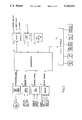
- FIG. 7 is a block diagram showing the functional elements of the retrofit speed indicator display unit
- FIG. 8 is a block and schematic diagram of the basic speed display circuitry for the retrofit speed indicator display unit.
- FIG. 9 is a schematic diagram of the brightness control for the LEDs of the retrofit speed indicator display unit.
- FIG. 1 there is shown the face 10 of the solid state speed indicator according to a preferred embodiment of the invention.
- the face 10 is screw mounted to a housing (not shown) by screws 11 at each of its four corners and serves as a closure to the housing.
- a first plurality of LEDs 12 are arranged in an arc generally centrally located on the face 10.
- the first or zero mile per hour LED is always on, and as speed increases, successive LEDs are lighted, presenting an increasing lighted arc to the engineer and simulating the moving indicator of prior analog speed indicators.
- a second plurality of LEDs 13 are arranged in an arc having a smaller radius but on a common center with the first arc of LEDs. In the preferred embodiment shown, there are 17 of these LEDs at five mile per hour increments.
- the LEDs 13 are always lighted and represent cardinal points on the speed indicator.
- decimal numerals 14 At zero and ten mile per hour increments are decimal numerals 14 from zero to eighty.
- the decimal numerals are formed by etching or otherwise forming the numerals in a mask on the back surface of the face 10 so that the places where the numerals are formed are transparent.
- each of these decimal numerals are back lighted by planar LEDs so that, like the LEDs 13, cardinal points of the display are always lighted, but here with numerals at increments of ten miles per hour.
- the dual range feature of the preferred embodiment of the invention is implemented by selectively illuminating the zero numerals in the ten to eighty decimal numeral displays. The first zero is always illuminated, but by turning off the LEDs back lighting the other zeros, the display functions as a speed indicator for the range of zero to eight miles per hour. When displaying in this range, the speed indicator cooperates with the timer circuit for drag operation described in the above mentioned U.S. Pat. No. 4,862,433.
- an acceleration display 15 is provided.
- This display comprises three numerical seven-segment LED devices to provide the engineer with a quantitative indication of acceleration from 0 to ⁇ 199 miles per hour per minute. Deceleration is indicated by a minus sign in the hundreds' position of the display. This quantitative display is useful information for the engineer in controlling the locomotive.
- arrows indicating acceleration or deceleration are provided to replace the numerical display in this version.
- an odometer display 17 In the upper right hand corner of the speed indicator face 10 is an odometer display 17.
- This display comprises five numerical seven-segment LED devices to provide the engineer with a quantitative indication of distance traveled in feet. This display is useful to the engineer in a depot or loading operation, allowing precise positioning of cars in the consist adjacent a loading dock, for example.
- the odometer display is driven by the microprocessor, which calculates distance traveled in feet for a preset wheel diameter, when this function is activated by the engineer.
- the prior analog speed indicator provides an indication of overspeed.
- This function has been implemented in the preferred embodiment of the solid state speed indicator, as well. This is done by using the odometer display 17. This display is normally blanked at speed; therefore, it is available for providing an overspeed warning to the engineer.
- the seven-segment devices can be used to display alpha characters, a suitable warning can be provided.
- the alpha display "OSP” can be displayed on the LEDs which comprise the odometer display 17. If, for example, seventy miles per hour and above represents an overspeed condition, then at sixty-five miles per hour, the alpha display "OSP" can be displayed by flashing, and this flashing display maintained until sixty-nine miles per hour.
- the alpha display "OSP" is displayed without flashing and the signal to the external brake valve is de-activated. It will of course be understood that the overspeed indicator could be a separate display or that an alpha display other than "OSP" could be displayed.
- the circuitry is implemented on three printed circuit boards, one for the power supply, one for the microprocessor and one for the display.
- the two or three boards may be conveniently stacked within the housing to provide a very compact packaging of the speed indicator.
- the display printed circuit board 20 is illustrated in FIG. 2. Here the placement of the LEDs is evident, the diodes DS0 to DS80 being the eighty-one LEDs 12 and the diodes DS98 to DS114 being the 17 LEDs 13, shown in FIG. 1.
- the planar LEDs DS81 to DS97 are used to back light the numerals 14, shown in FIG. 1. Planar LEDs DS83, DS85, DS87, DS89, DS91, DS93, DS95, and DS97 illuminate the zeros for the decimal numerals ten to eighty, and these are the LEDs which are selectively energized to provide the dual range function.
- LED devices DS116, DS122 and 123 are seven-segment displays used for the acceleration and odometer displays.
- Various other circuit elements including integrated circuits (indicated by the "U” prefix), resistors (indicated by the “R” prefix), capacitors (indicated by the “C” prefix), and transistors (indicated by the "Q” prefix) are also shown on the printed circuit board. These constitute the display driver circuitry which is controlled by the microprocessor.
- a connector J1 indicated in dotted line outline. This connector is on the reverse side of the printed circuit board and provides the connections to the microprocessor, and thereby to the power supply, printed circuit board.
- FIG. 3 is a high level block diagram of the circuitry for the solid state speed indicator.
- the solid state speed indicator uses a microcomputer 26 of conventional design based on an Intel 80C32 microprocessor, electrically programmable read only memory (EPROM), volatile random access memory (RAM), and non-volatile electrically erasable and programmable read only memory (EEPROM).
- EPROM electrically programmable read only memory
- RAM volatile random access memory
- EEPROM non-volatile electrically erasable and programmable read only memory
- Speed sensing is performed by a generator 21, mechanically coupled to a locomotive axle, which produces a generally sinusoidal signal having a frequency proportional to speed. This signal is processed by a low pass filter and pulse shaper 22 to produce a square wave output.
- the microcomputer 26 receives the following inputs: the conditioned axle signal from pulse shaper 22, jumper settings defining the type of axle generator (e.g., 20 or 60 pole) from jumper options 23, conditioned locomotive signals defining forward or reverse direction from the 74 V inputs 24, and operator control switch inputs from the switches 25 providing settings such as dimmer, overspeed, and wheel diameter.
- the microcomputer 26 uses these inputs and the control program internally stored in EPROM, calculates and generates all the signals needed to drive the display controller 30 and produce the correct dynamic display of speed, acceleration, odometer, and overspeed in accordance with the display presentation techniques previously described.
- Speed or velocity is determined by processing the conditioned axle signal from pulse shaper 22. Acceleration is computed by differentiating and properly filtering velocity, and distance is computed by counting axle events and knowing the wheel diameter setting.
- microcomputer 26 generates external overspeed, remote display, and recorder output signals using output circuitry 27.
- Non-volatile memory 29 is used to retain the last-selected values of the wheel diameter, overspeed, and dimmer settings.
- DC operating power for the microcomputer 26, display controller 30, and other circuitry is derived from the 74 volt DC locomotive supply using power supply 28.
- FIG. 4 shows the organization of the major software modules which constitute the control program stored in EPROM.
- the system is initially turned on, the main program 31 is initialized by an initialize routine 32 that performs a system check. Inputs to the main program 31 are via interrupts, including display drive 33, axle pulse 34 and recorder output 35 interrupts.
- the modules of the motion routines 36 respectively calculate velocity, acceleration and distance, check overspeed and service the odometer.
- the modules of the control routines 37 read the input switches and process the control states.
- the modules of the display routines format the arc display, the acceleration display and the odometer display.
- the various routines and modules are themselves straight forward and readily implemented based on functional description of the solid state speed indicator, supra.
- FIG. 5 of the drawings there is shown the face 40 which forms a part of a retrofit display unit for the prior meter movement speed indicators.
- the retrofit unit comprises a replacement door 41 in which the face 40 and its supporting circuitry is installed by means of cap screws 42.
- This retrofit speed indicator display face is quite similar to that shown in FIG. 1 and includes a first plurality of LEDs 43 arranged in an arc, each of these LEDs representing increments of one mile per hour.
- a second plurality of LEDs 44 are arranged in an arc within the first arc and, again, represent five mile per hour increments.
- Decimal numerals 45 from zero to eighty at ten mile per hour increments are formed in a mask on the back surface of the face 40, and these decimal numerals are back lighted by planar LEDs.
- the indicia described thus far perform the same functions as the indicia 12, 13 and 14 shown in FIG. 1.
- the retrofit speed indicator display face 40 in FIG. 5 provides separate indicia 46, 47 and 48 in the form of an up arrow, a bar and a down arrow, respectively.
- the up arrow 46 will be lighted; if the locomotive is decelerating, the down arrow 48 will be lighted; but if the locomotive is at constant velocity, the bar 47 will be lighted.
- the bar 47 is lighted as long as acceleration or deceleration is within a predetermined range, say ⁇ 2 miles per hour per minute. This serves to stabilize the display so that the arrows 46 and 48 are not alternately flashing under some conditions.
- the acceleration display in this retrofit indicator display is threshold-sensing and qualitative rather than a quantitative display.
- the retrofit speed indicator display does not include an odometer. Nevertheless, the overspeed function is supported by an LED 49 in the upper right hand corner of the display face. This LED begins flashing when speed is within a predetermined limit, say five or six miles per hour, lower than a preset speed, say 70 miles per hour, with the LED lighted continuously at and above the preset speed.
- FIG. 6 is similar to FIG. 2 but for the face 40 shown in FIG. 5.
- the planar LEDs designated as 8376 provide the back lighting for the acceleration indicia 46, 47 and 48.
- the LED designated 2111 in the upper right hand corner of the printed circuit board provides the overspeed indication function. It will be noted here, however, that instead of two planar LEDs for the decimal numerals, only a single planar LED, designated 8378, is provided for each of the decimal numerals.
- This particular model of the retrofit display does not support the dual speed function because not all customers desire or specify that function. It will be understood, however, that the retrofit display may be provided with the dual speed function just as the solid state speed indicator shown in FIGS. 1 to 4.
- FIG. 7 is a block diagram of the additional circuitry needed to implement a solid state LED display for retrofit to an existing Pulse speed indicator.
- This circuitry unlike that of FIG. 3, does not use a microcomputer.
- the FIG. 7 circuitry connects to the control electronics of a standard Pulse analog speed indicator by means of a nine wire cable. This cable brings in all the needed interface signals, including a voltage representation of the speed signal itself (denoted as speed feedback or fbk).
- the speed signal is filtered and amplified by amplifier 51.
- the amplified signal is applied simultaneously to the input of eight LM3914 integrated circuit (IC) LED drivers 52 connected in series across respective taps of a precision resistive voltage divider (shown in FIG. 8) energized by a precision ten volt reference supply.
- the magnitude of the amplified speed signal, relative to the reference voltage, determines which of the eighty speed LEDs 43 are illuminated.
- FIG. 8 shows the details of interconnecting the eights LM3914 devices.
- an external voltage divider made up of eight equal value precision (1% or better) resistors
- the voltage applied to the internal voltage divider of each LM3914 is constrained to be very close to 1.250 volts.
- the value R of each resistor in the external divider is selected low enough so that it swamps out tolerance and temperature variations in the internal LM3914 voltage divider. Since the internal voltage reference of the LM3914 devices are not used, the major error in sensing proper turn-on threshold for each speed arc LED is due to internal offset voltages within each LM3914.
- the voltage impressed across each LM3914 should be maximized in order to minimize LM3914 offset effects.
- a ninth LM3914 IC 53 is DC biased to always illuminate the seventeen cardinal point LEDs 44 plus the first LED of the speed arc which represents zero miles per hour.
- a tenth LM3914 IC 54 activates the nine planar LEDs which light the decimal numerals zero to eighty.
- the LEDs connected to LM3914 ICs 53 and 54 are illuminated independent of speed, thereby forming the calibration indicia for the speed indicator.
- an eleventh LM3914 LED driver would be used to separately control eight planar LEDs which selectively back light the zeros in the decimal numerals ten to eighty.
- a switchable range amplifier would be configured in the speed channel to amplify the speed signal by a factor of ten. Both the LED driver and the gain of ten amplifier would be switchable under the control of a signal from the drag logic, such that on the low speed range, the back light zeros are turned off and the amplifier gain is increased.
- An important and unique design feature of the retrofit indicator is the circuit technique used to implement simultaneous brightness control of all LED display devices.
- the brightness control of all LEDs controlled by any one LM3914 integrated circuit is set by a resistor connected between pins 7 and 8. Since at least ten LM3914 drivers are used in one preferred embodiment, a means was needed to individually slave the brightness control of these ten drivers to a single control device. This is accomplished by using ten current sinking transistors, generally indicated at 55 in FIG. 7, individually connected to pin 7 of each LM3914.
- FIG. 9 shows this connection for three of the LM3914 Ics, and it will be understood that the connections shown are typical.
- the base element of each current sink is connected in parallel (through a suitable isolation network) to the wiper of the brightness control potentiometer. In this way, it is possible with a single user control to adjust and maintain intensity tracking of the LED display devices over a wide brightness range.
- the ten current sinking transistors individually connected to pin 7 of each LM3914 are simultaneously pulsed with a variable duty cycle signal which controls their conduction interval.
- the repetition frequency should be greater than a few hundred Hertz to avoid stroboscopic motion effects and to allow the persistence of the eye to integrate and average the light pulses in the LEDs connected to each LM3914 driver IC.
- the brightness control potentiometer is a component of a duty cycle generator and acts to vary, under user control, the output duty cycle and thus the overall display brightness. Since the current sinking transistors in this variation are always switched either fully on or fully off, any changes in their linear characteristics with temperature are effectively eliminated.
- the only computing performed by this retrofit embodiment is an analog differentiation of the amplified speed signal by the differentiator 56 to generate an acceleration signal.
- the acceleration signal is applied to a pair of comparators 58 and 57 which determine, respectively, whether there is net acceleration or deceleration.
- these comparators have a threshold equivalent to two miles per hour per minute so that there will be no output from either of the comparators unless acceleration or deceleration exceeds that equivalent threshold.
- An output from comparator 58 energizes the up arrow 46 signifying acceleration, while an output from comparator 57 energizes the down arrow 48 signifying deceleration.
- NAND logic 59 receives outputs from both the comparators 57 and 58, and when there is no output from either of the two comparators, logic 59 energizes the bar LED 47 signifying constant locomotive speed. Note that the actual drive current through these LEDs is controlled by the LM3914 LED driver 54 so that the brightness of the LEDs 46, 47 and 48 also track the overall display brightness.
- the speed signal is also supplied to an overspeed warning comparator 61 which receives a reference voltage derived from an overspeed summing amplifier 62.
- the summing amplifier 62 has an input, overspeed level, which is derived from a user adjustable control on the basic analog speed indicator unit. The user adjusts the overspeed level to a desired setting.
- the overspeed warning comparator 61 then provides an output to control logic 63 when the speed is within some predetermined range, say five miles per hour, lower than the overspeed limit the user has selected. Under these conditions, LED 49 flashes at a rate determined by square wave oscillator 64 to provide a warning that the selected overspeed limit is being approached.
- the overspeed switch signal into control logic 63 turns LED 49 on continuously, there by overriding the flashing action of the square wave oscillator and signaling the overspeed condition to the operator. Simultaneously, in the basic speed indicator electronics (not shown), a control relay is energized when overspeed is reached. Note again that the actual drive current through this LED is controlled by the LM3914 LED driver 53 so that the brightness of LED 49 also tracks the overall display brightness.
- the door retrofit speed indicator display operates on its own power supply which generates the necessary voltages directly from the locomotive 74 volt DC power.
- the +10 volt reference supply which is critical to the overall accuracy of speed indicator display, is developed from the +15 volt supply using an inexpensive, yet high precision, integrated circuit device.
Abstract
Description
Claims (15)
Priority Applications (1)
| Application Number | Priority Date | Filing Date | Title |
|---|---|---|---|
| US07/742,177 US5166610A (en) | 1990-10-02 | 1991-08-02 | Dual range speed indicator with acceleration display |
Applications Claiming Priority (2)
| Application Number | Priority Date | Filing Date | Title |
|---|---|---|---|
| US59171490A | 1990-10-02 | 1990-10-02 | |
| US07/742,177 US5166610A (en) | 1990-10-02 | 1991-08-02 | Dual range speed indicator with acceleration display |
Related Parent Applications (1)
| Application Number | Title | Priority Date | Filing Date |
|---|---|---|---|
| US59171490A Continuation | 1990-10-02 | 1990-10-02 |
Publications (1)
| Publication Number | Publication Date |
|---|---|
| US5166610A true US5166610A (en) | 1992-11-24 |
Family
ID=27081223
Family Applications (1)
| Application Number | Title | Priority Date | Filing Date |
|---|---|---|---|
| US07/742,177 Expired - Fee Related US5166610A (en) | 1990-10-02 | 1991-08-02 | Dual range speed indicator with acceleration display |
Country Status (1)
| Country | Link |
|---|---|
| US (1) | US5166610A (en) |
Cited By (10)
| Publication number | Priority date | Publication date | Assignee | Title |
|---|---|---|---|---|
| US5517183A (en) * | 1992-06-19 | 1996-05-14 | The United States Of America As Represented By The Administrator Of The National Aeronautics And Space Administration | Accelerometer method and apparatus for integral display and control functions |
| US5714929A (en) * | 1994-12-02 | 1998-02-03 | Liu; Paul | Microprocessor-controlled speedometer/odometer |
| US6215298B1 (en) * | 1998-11-25 | 2001-04-10 | Auto Meter Products, Inc. | Dual range tachometer |
| FR2808873A1 (en) * | 2000-05-12 | 2001-11-16 | Francis Lafon | Noise level meter has row of lights to indicate noise intensity in manner suitable for non-professional user |
| US20050139143A1 (en) * | 2003-12-30 | 2005-06-30 | Nancy Dinh | Analog instrument gauge display |
| US20070182537A1 (en) * | 2004-06-07 | 2007-08-09 | Sharp Kabushiki Kaisha | Display system for vehicle and vehicle |
| US20110169814A1 (en) * | 2010-01-14 | 2011-07-14 | Cypress Semiconductor Corporation | Digital driving circuits, methods and systems for liquid crystal display devices |
| US20130092075A1 (en) * | 2011-10-13 | 2013-04-18 | Christopher J. Volpe | Digital meter |
| US10135379B2 (en) * | 2015-09-18 | 2018-11-20 | Kabushiki Kaisha Yaskawa Denki | State display device of industrial machinery and power conversion device |
| US11681477B1 (en) * | 2022-01-13 | 2023-06-20 | Xerox Corporation | Automated print engine speed control |
Citations (3)
| Publication number | Priority date | Publication date | Assignee | Title |
|---|---|---|---|---|
| US3619574A (en) * | 1968-04-08 | 1971-11-09 | Time Systems Corp | Digital meter with auxiliary visual analog display |
| US4199758A (en) * | 1978-05-04 | 1980-04-22 | Helm Instrument Co., Inc. | Solid state indicating apparatus |
| US4243985A (en) * | 1978-05-04 | 1981-01-06 | Chronolog Systems Limited | Analogue voltage indicator with sequence of light emitting diodes |
-
1991
- 1991-08-02 US US07/742,177 patent/US5166610A/en not_active Expired - Fee Related
Patent Citations (3)
| Publication number | Priority date | Publication date | Assignee | Title |
|---|---|---|---|---|
| US3619574A (en) * | 1968-04-08 | 1971-11-09 | Time Systems Corp | Digital meter with auxiliary visual analog display |
| US4199758A (en) * | 1978-05-04 | 1980-04-22 | Helm Instrument Co., Inc. | Solid state indicating apparatus |
| US4243985A (en) * | 1978-05-04 | 1981-01-06 | Chronolog Systems Limited | Analogue voltage indicator with sequence of light emitting diodes |
Non-Patent Citations (2)
| Title |
|---|
| Product Description; Brocksopp Engineering; BE 4C 0 80, Dual Range Speedometer; Feb. 9, 1990. * |
| Product Description; Brocksopp Engineering; BE-4C 0-80, Dual Range Speedometer; Feb. 9, 1990. |
Cited By (16)
| Publication number | Priority date | Publication date | Assignee | Title |
|---|---|---|---|---|
| US5517183A (en) * | 1992-06-19 | 1996-05-14 | The United States Of America As Represented By The Administrator Of The National Aeronautics And Space Administration | Accelerometer method and apparatus for integral display and control functions |
| US5714929A (en) * | 1994-12-02 | 1998-02-03 | Liu; Paul | Microprocessor-controlled speedometer/odometer |
| US6215298B1 (en) * | 1998-11-25 | 2001-04-10 | Auto Meter Products, Inc. | Dual range tachometer |
| FR2808873A1 (en) * | 2000-05-12 | 2001-11-16 | Francis Lafon | Noise level meter has row of lights to indicate noise intensity in manner suitable for non-professional user |
| US20050139143A1 (en) * | 2003-12-30 | 2005-06-30 | Nancy Dinh | Analog instrument gauge display |
| US7129849B2 (en) * | 2003-12-30 | 2006-10-31 | General Motors Corporation | Analog instrument gauge display |
| US9140716B2 (en) * | 2004-06-07 | 2015-09-22 | Sharp Kabushiki Kaisha | Display system for vehicle and vehicle |
| US20070182537A1 (en) * | 2004-06-07 | 2007-08-09 | Sharp Kabushiki Kaisha | Display system for vehicle and vehicle |
| US9852702B2 (en) | 2010-01-14 | 2017-12-26 | Cypress Semiconductor Corporation | Digital driving circuits, methods and systems for display devices |
| US8704818B2 (en) | 2010-01-14 | 2014-04-22 | Cypress Semiconductor Corporation | Digital driving circuits, methods and systems for liquid crystal display devices |
| US8773420B2 (en) * | 2010-01-14 | 2014-07-08 | Cypress Semiconductor Corporation | Digital driving circuits, methods and systems for liquid crystal display devices |
| US20110169814A1 (en) * | 2010-01-14 | 2011-07-14 | Cypress Semiconductor Corporation | Digital driving circuits, methods and systems for liquid crystal display devices |
| US20130092075A1 (en) * | 2011-10-13 | 2013-04-18 | Christopher J. Volpe | Digital meter |
| US10135379B2 (en) * | 2015-09-18 | 2018-11-20 | Kabushiki Kaisha Yaskawa Denki | State display device of industrial machinery and power conversion device |
| US11681477B1 (en) * | 2022-01-13 | 2023-06-20 | Xerox Corporation | Automated print engine speed control |
| US20230221902A1 (en) * | 2022-01-13 | 2023-07-13 | Xerox Corporation | Automated print engine speed control |
Similar Documents
| Publication | Publication Date | Title |
|---|---|---|
| US5166610A (en) | Dual range speed indicator with acceleration display | |
| EP0114018B1 (en) | Display unit for trip computer | |
| US6046686A (en) | Violation alert speed display | |
| US4281388A (en) | Tachometer | |
| US4102191A (en) | Digital fuel gauge | |
| US4357594A (en) | Vehicular hazard warning system | |
| US4388558A (en) | Display intensity control apparatus | |
| US4210908A (en) | Two-dimensional display apparatus for an automobile | |
| US4520663A (en) | Vehicle brake test apparatus | |
| US3780272A (en) | Electronic odometer and comparative rate indicator | |
| US4007419A (en) | Digital bicycle speedometer-odometer | |
| US4463355A (en) | Solid state mach/air speed indicator | |
| US5269187A (en) | Automotive accelerometer | |
| US3950700A (en) | Vehicle performance control system | |
| US4244210A (en) | Combined fuel level and fuel consumption indicator | |
| US3835382A (en) | Vehicle performance indicator system | |
| US3888118A (en) | Method and apparatus for determining road roughness | |
| US4242980A (en) | Displaying measuring instrument | |
| US3477022A (en) | Electronic speedometer and odometer control circuit | |
| EP0274257B1 (en) | Gauge driving system | |
| US3906345A (en) | Electro optical meter system having a series lighting display and matrix scanning | |
| GB2255411A (en) | Vehicle speedometer | |
| US3961256A (en) | Light-emitting semiconductor display apparatus for displaying a band representation of a voltage analog of a measured parameter | |
| US5714929A (en) | Microprocessor-controlled speedometer/odometer | |
| WO1987003978A1 (en) | Vehicular speedometer having acceleration and deceleration indicating means |
Legal Events
| Date | Code | Title | Description |
|---|---|---|---|
| AS | Assignment |
Owner name: PULSE ELECTRONICS, INC. A DELAWARE CORPORATION Free format text: ASSIGNMENT OF ASSIGNORS INTEREST;ASSIGNOR:PULSE ELECTRONICS, INC., A VIRGINIA CORPORATION;REEL/FRAME:007338/0120 Effective date: 19950131 |
|
| FEPP | Fee payment procedure |
Free format text: PAT HLDR NO LONGER CLAIMS SMALL ENT STAT AS INDIV INVENTOR (ORIGINAL EVENT CODE: LSM1); ENTITY STATUS OF PATENT OWNER: LARGE ENTITY |
|
| FEPP | Fee payment procedure |
Free format text: PAYOR NUMBER ASSIGNED (ORIGINAL EVENT CODE: ASPN); ENTITY STATUS OF PATENT OWNER: LARGE ENTITY |
|
| FPAY | Fee payment |
Year of fee payment: 4 |
|
| SULP | Surcharge for late payment | ||
| REMI | Maintenance fee reminder mailed | ||
| FEPP | Fee payment procedure |
Free format text: PAYER NUMBER DE-ASSIGNED (ORIGINAL EVENT CODE: RMPN); ENTITY STATUS OF PATENT OWNER: LARGE ENTITY Free format text: PAYOR NUMBER ASSIGNED (ORIGINAL EVENT CODE: ASPN); ENTITY STATUS OF PATENT OWNER: LARGE ENTITY |
|
| AS | Assignment |
Owner name: CHASE MANHATTAN BANK, THE, NEW YORK Free format text: SECURITY INTEREST;ASSIGNOR:WESTINGHOUSE AIR BRAKE COMPANY;REEL/FRAME:009423/0239 Effective date: 19980630 |
|
| AS | Assignment |
Owner name: WESTINGHOUSE AIR BRAKE COMPANY, PENNSYLVANIA Free format text: ASSIGNMENT OF ASSIGNORS INTEREST;ASSIGNOR:PULSE ELECTRONICS, INC;REEL/FRAME:010144/0879 Effective date: 19971231 |
|
| FEPP | Fee payment procedure |
Free format text: PAYOR NUMBER ASSIGNED (ORIGINAL EVENT CODE: ASPN); ENTITY STATUS OF PATENT OWNER: LARGE ENTITY |
|
| FEPP | Fee payment procedure |
Free format text: PAYER NUMBER DE-ASSIGNED (ORIGINAL EVENT CODE: RMPN); ENTITY STATUS OF PATENT OWNER: LARGE ENTITY |
|
| REMI | Maintenance fee reminder mailed | ||
| FPAY | Fee payment |
Year of fee payment: 8 |
|
| SULP | Surcharge for late payment |
Year of fee payment: 7 |
|
| AS | Assignment |
Owner name: WESTINGHOUSE AIR BRAKE COMPANY, PENNSYLVANIA Free format text: TERMINATION OF SECURITY INTEREST RECORDAL STARTING AT REEL/FRAME 9423/0239.;ASSIGNOR:CHASE MANHATTAN BANK, AS COLLATERAL AGENT, THE;REEL/FRAME:012280/0283 Effective date: 20010501 |
|
| REMI | Maintenance fee reminder mailed | ||
| LAPS | Lapse for failure to pay maintenance fees | ||
| STCH | Information on status: patent discontinuation |
Free format text: PATENT EXPIRED DUE TO NONPAYMENT OF MAINTENANCE FEES UNDER 37 CFR 1.362 |
|
| FP | Lapsed due to failure to pay maintenance fee |
Effective date: 20041124 |