US5140700A - FM resonant filter having AM frequency bypass - Google Patents
FM resonant filter having AM frequency bypass Download PDFInfo
- Publication number
- US5140700A US5140700A US07/624,428 US62442890A US5140700A US 5140700 A US5140700 A US 5140700A US 62442890 A US62442890 A US 62442890A US 5140700 A US5140700 A US 5140700A
- Authority
- US
- United States
- Prior art keywords
- signal path
- signals
- inductor
- signal
- receiver
- Prior art date
- Legal status (The legal status is an assumption and is not a legal conclusion. Google has not performed a legal analysis and makes no representation as to the accuracy of the status listed.)
- Expired - Lifetime
Links
Images
Classifications
-
- H—ELECTRICITY
- H04—ELECTRIC COMMUNICATION TECHNIQUE
- H04B—TRANSMISSION
- H04B1/00—Details of transmission systems, not covered by a single one of groups H04B3/00 - H04B13/00; Details of transmission systems not characterised by the medium used for transmission
- H04B1/06—Receivers
- H04B1/16—Circuits
- H04B1/18—Input circuits, e.g. for coupling to an antenna or a transmission line
-
- H—ELECTRICITY
- H03—ELECTRONIC CIRCUITRY
- H03H—IMPEDANCE NETWORKS, e.g. RESONANT CIRCUITS; RESONATORS
- H03H5/00—One-port networks comprising only passive electrical elements as network components
- H03H5/02—One-port networks comprising only passive electrical elements as network components without voltage- or current-dependent elements
-
- H—ELECTRICITY
- H03—ELECTRONIC CIRCUITRY
- H03J—TUNING RESONANT CIRCUITS; SELECTING RESONANT CIRCUITS
- H03J1/00—Details of adjusting, driving, indicating, or mechanical control arrangements for resonant circuits in general
- H03J1/0008—Details of adjusting, driving, indicating, or mechanical control arrangements for resonant circuits in general using a central processing unit, e.g. a microprocessor
Definitions
- the present invention relates in general to radio receivers having a filtered RF input, and more specifically to AM/FM automotive radio receivers having an FM resonant input filter which conducts AM frequency signals substantially unattenuated.
- Radio receivers must select a single broadcast from many strong and weak signals that may be present at the receiving antenna.
- the selectivity of a receiver refers to its ability to discriminate between a signal of interest and other signals at adjacent frequencies. This selectivity is typically achieved by bandpass filtering.
- the radio-frequency (RF) signals are frequency shifted by mixing with an oscillator signal so that the RF signal of interest is shifted to an intermediate frequency (IF) which is typically lower than the RF frequency.
- IF intermediate frequency
- a fixed IF filter is then used to reject signals at frequencies other than the IF frequencies so that filtering at the RF frequency stage is not necessary.
- Resonant circuits typically provide the filtering used at RF frequencies.
- a series resonant circuit located between an antenna and the input of a receiver can be provided having a controllable resonant frequency.
- a variable inductor connected in series with a capacitor are adapted to resonate throughout the FM frequency band.
- a tuning voltage generated in the receiver controls the resonant frequency of the series resonant filter to coincide with the signal of interest while attenuating other signals.
- This resonant circuit can be employed in combination with other series or parallel resonant circuits connected between the antenna and the receiver input or the receiver input and signal ground.
- a bandpass filter having a resonant circuit connected in a single signal path between an AM/FM radio receiver and an AM/FM antenna.
- the resonant circuit includes a variable inductance connected in series with a capacitance.
- a bypass inductor is coupled in parallel with the capacitance for bypassing AM signals in the signal path around the capacitance.
- the bypass inductor is a fixed inductor having a self-resonant frequency located between the AM and FM bands.
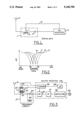
- FIG. 1 is a schematic diagram illustrating a bandpass filter according to the prior art.
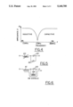
- FIG. 2 shows a plot of attenuation versus frequency for a bandpass filter in accordance with FIG. 1.
- FIG. 3 is a schematic diagram showing a preferred embodiment of the present invention.
- FIG. 4 shows a plot of impedance versus frequency for a preferred bypass inductor according to the invention of FIG. 3.
- FIG. 5 shows an equivalent circuit of the bandpass filter operating in the FM frequency band.
- FIG. 6 shows an equivalent circuit of the bandpass filter operating in the AM frequency band.
- a basic radio system includes an antenna 10 connected to a bandpass filter 11 and an FM receiver 12.
- Filter 11 includes a series resonant circuit having a variable inductor 13 in series with a capacitor 14.
- a control line 15 carries a control signal from FM receiver 12 to variable inductor 13 to shift the resonant frequency of the series resonant circuit (i.e., the center frequency of the passband) in accordance with the tuning voltage developed in the receiver for controlling the mixing oscillator (not shown).
- bandpass filter 11 may exhibit a variable attenuation versus frequency curve as shown in FIG. 2.
- a resonant characteristic curve 16 is exhibited by the filter at a first value of the tuning control signal whereby the center of the passband coincides with the RF signal of interest which is desired to be mixed to the IF frequency of the receiver.
- other values of the tuning control signal shift the resonant characteristic as shown at curves 17-19.
- the prior art receiver shown in FIG. 1 prevents AM signals received by the antenna from reaching the receiver. Therefore, AM signals cannot be received in receiver 12 unless a separate signal path is provided for AM signals.
- the present invention for providing a series resonant filter for FM signals and for allowing the transmission of AM signals through a single signal path is shown in FIG. 3.
- Antenna 10 is connected to a variable inductor 20 having an inductor winding 21 wound on a first magnetic core segment 22.
- a core segment 23 having a higher permeability than segment 22 forms a closed magnetic circuit with core segment 22.
- a magnetizing winding 24 is wound on core segment 23 and controls the inductance of inductor winding 21 by virtue of the current carried by winding 24.
- a capacitor 25 and an inductor 26 is connected in series with inductor 21 thus forming a resonant circuit 27 which is connected to an RF input block 30 in an AM/FM receiver 28.
- a superheterodyne receiver is shown wherein RF signals in RF block 30 are mixed to an intermediate frequency and provided to an IF block 31 and a detector 32. Detector 32 is connected to an output transducer 33.
- a microcontroller 35 for controlling receiver operation is connected to a tuning circuit 34.
- Tuning circuit 34 provides a mixing signal to RF input block 30 and a filter control signal to magnetizing winding 24.
- series resonant circuit 27 is adapted to have a variable resonant frequency controllable throughout the FM band.
- Microcontroller 35 receives an operator input (not shown) for commanding a frequency to be received.
- a digital frequency command is provided by microcontroller 35 to tuning ciruit 34 which converts the command to analog signals for controlling the frequency of a mixing signal and the resonant frequency of resonant circuit 27 in a conventional manner.
- tuning ciruit 34 which converts the command to analog signals for controlling the frequency of a mixing signal and the resonant frequency of resonant circuit 27 in a conventional manner.
- the input RF signals of interest are centered in the passband of the resonant filter.
- inductor 26 is provided for bypassing capacitor 25 as shown.
- Bypass inductor 26 has a characteristic as shown in FIG. 4, wherein the self-resonant frequency of the bypass inductor is located intermediate of the AM and the FM bands and may have a preferred frequency of about 21 megahertz.
- the impedance of the bypass inductor is a capacitive impedance in the FM frequency range and is an inductive impedance in the AM frequency range.
- FIG. 5 The resulting equivalent circuit at FM frequencies is shown in FIG. 5, wherein the series resonant circuit behaves as though a capacitor 40 were connected in parallel with capacitor 25 since bypass inductor 26 has a capacitive impedance at FM frequencies. Thus, the series resonant character of the circuit is maintained. Since the effective capacitance of bypass inductor 26 is substantially constant across the FM band (typically about 3 picofarads), the capacitance value of capacitor 25 can be reduced to compensate for the added capacitance of bypass inductor 26.
- AM signals The equivalent circuit seen by AM signals is shown in FIG. 6, including an equivalent inductor 41 corresponding to variable inductor 20. Both bypass inductor 26 and equivalent inductor 41 have a small inductive impedance at AM frequencies. Thus, AM signals bypass the blocking capacitance of capacitor 25 and reach the receiver using a single signal path having a low impedance.
Abstract
Description
Claims (11)
Priority Applications (1)
| Application Number | Priority Date | Filing Date | Title |
|---|---|---|---|
| US07/624,428 US5140700A (en) | 1990-12-07 | 1990-12-07 | FM resonant filter having AM frequency bypass |
Applications Claiming Priority (1)
| Application Number | Priority Date | Filing Date | Title |
|---|---|---|---|
| US07/624,428 US5140700A (en) | 1990-12-07 | 1990-12-07 | FM resonant filter having AM frequency bypass |
Publications (1)
| Publication Number | Publication Date |
|---|---|
| US5140700A true US5140700A (en) | 1992-08-18 |
Family
ID=24501981
Family Applications (1)
| Application Number | Title | Priority Date | Filing Date |
|---|---|---|---|
| US07/624,428 Expired - Lifetime US5140700A (en) | 1990-12-07 | 1990-12-07 | FM resonant filter having AM frequency bypass |
Country Status (1)
| Country | Link |
|---|---|
| US (1) | US5140700A (en) |
Cited By (8)
| Publication number | Priority date | Publication date | Assignee | Title |
|---|---|---|---|---|
| US5375260A (en) * | 1990-12-27 | 1994-12-20 | Samson Technologies | Receiver unit for wireless microphone applications |
| US5379452A (en) * | 1992-03-13 | 1995-01-03 | Robert Bosch Gmbh | Active frequency separating circuit |
| US5548830A (en) * | 1993-12-27 | 1996-08-20 | Ford Motor Company | Dual-band frequency-selective attenuator for automatic gain control |
| EP1026830A1 (en) * | 1997-01-20 | 2000-08-09 | Yokowo Co., Ltd. | Antenna circuit |
| US20040023619A1 (en) * | 2002-07-10 | 2004-02-05 | Alps Electric Co., Ltd. | Transmission-and-receiving switching circuit not allowing superfluous signals to be input or output |
| WO2006080062A1 (en) * | 2005-01-27 | 2006-08-03 | Mitsubishi Denki Kabushiki Kaisha | Switch circuit |
| US20070046546A1 (en) * | 2005-08-31 | 2007-03-01 | Tdk Corporation | Monopole antenna |
| US7881692B2 (en) | 2004-06-30 | 2011-02-01 | Silicon Laboratories Inc. | Integrated low-IF terrestrial audio broadcast receiver and associated method |
Citations (10)
| Publication number | Priority date | Publication date | Assignee | Title |
|---|---|---|---|---|
| US3360730A (en) * | 1964-10-16 | 1967-12-26 | Smith James E | Apparatus providing a-m radio reception of f-m |
| US4157547A (en) * | 1977-03-10 | 1979-06-05 | Tenna Corporation | Splitter for antenna for AM-FM, CB and method of conversion |
| US4334323A (en) * | 1980-09-08 | 1982-06-08 | Zenith Radio Corporation | Self tracking tuner |
| US4406019A (en) * | 1981-11-16 | 1983-09-20 | The Bendix Corporation | Selectivity means in amplitude modulated radio receivers |
| JPS5964930A (en) * | 1982-10-06 | 1984-04-13 | Nippon Technical Co Ltd | Agc circuit |
| US4736457A (en) * | 1985-03-16 | 1988-04-05 | U.S. Philips Corporation | Circuit arrangement for a tuner for changing over two frequency bands |
| US4881272A (en) * | 1987-03-30 | 1989-11-14 | Kabushiki Kaisha Toshiba | Multi-band FM receiver for receiving FM broadcasting signals and TV broadcasting sound signals |
| US4972353A (en) * | 1989-02-21 | 1990-11-20 | Ford Motor Company | Radio-frequency transformer providing automatic gain control and overload protection |
| US5020145A (en) * | 1986-03-05 | 1991-05-28 | Goldstar Co., Ltd. | AM/FM band selector |
| US5040239A (en) * | 1988-08-30 | 1991-08-13 | Toko, Inc. | Tuning circuit and receiver |
-
1990
- 1990-12-07 US US07/624,428 patent/US5140700A/en not_active Expired - Lifetime
Patent Citations (10)
| Publication number | Priority date | Publication date | Assignee | Title |
|---|---|---|---|---|
| US3360730A (en) * | 1964-10-16 | 1967-12-26 | Smith James E | Apparatus providing a-m radio reception of f-m |
| US4157547A (en) * | 1977-03-10 | 1979-06-05 | Tenna Corporation | Splitter for antenna for AM-FM, CB and method of conversion |
| US4334323A (en) * | 1980-09-08 | 1982-06-08 | Zenith Radio Corporation | Self tracking tuner |
| US4406019A (en) * | 1981-11-16 | 1983-09-20 | The Bendix Corporation | Selectivity means in amplitude modulated radio receivers |
| JPS5964930A (en) * | 1982-10-06 | 1984-04-13 | Nippon Technical Co Ltd | Agc circuit |
| US4736457A (en) * | 1985-03-16 | 1988-04-05 | U.S. Philips Corporation | Circuit arrangement for a tuner for changing over two frequency bands |
| US5020145A (en) * | 1986-03-05 | 1991-05-28 | Goldstar Co., Ltd. | AM/FM band selector |
| US4881272A (en) * | 1987-03-30 | 1989-11-14 | Kabushiki Kaisha Toshiba | Multi-band FM receiver for receiving FM broadcasting signals and TV broadcasting sound signals |
| US5040239A (en) * | 1988-08-30 | 1991-08-13 | Toko, Inc. | Tuning circuit and receiver |
| US4972353A (en) * | 1989-02-21 | 1990-11-20 | Ford Motor Company | Radio-frequency transformer providing automatic gain control and overload protection |
Cited By (15)
| Publication number | Priority date | Publication date | Assignee | Title |
|---|---|---|---|---|
| US5375260A (en) * | 1990-12-27 | 1994-12-20 | Samson Technologies | Receiver unit for wireless microphone applications |
| US5379452A (en) * | 1992-03-13 | 1995-01-03 | Robert Bosch Gmbh | Active frequency separating circuit |
| US5548830A (en) * | 1993-12-27 | 1996-08-20 | Ford Motor Company | Dual-band frequency-selective attenuator for automatic gain control |
| EP1026830A1 (en) * | 1997-01-20 | 2000-08-09 | Yokowo Co., Ltd. | Antenna circuit |
| EP1026830A4 (en) * | 1997-01-20 | 2004-10-06 | Yokowo Seisakusho Kk | Antenna circuit |
| US20040023619A1 (en) * | 2002-07-10 | 2004-02-05 | Alps Electric Co., Ltd. | Transmission-and-receiving switching circuit not allowing superfluous signals to be input or output |
| US7881692B2 (en) | 2004-06-30 | 2011-02-01 | Silicon Laboratories Inc. | Integrated low-IF terrestrial audio broadcast receiver and associated method |
| US8532601B2 (en) | 2004-06-30 | 2013-09-10 | Silicon Laboratories Inc. | Integrated low-IF terrestrial audio broadcast receiver and associated method |
| US8249543B2 (en) | 2004-06-30 | 2012-08-21 | Silicon Laboratories Inc. | Low-IF integrated data receiver and associated methods |
| US8060049B2 (en) | 2004-06-30 | 2011-11-15 | Silicon Laboratories Inc. | Integrated low-if terrestrial audio broadcast receiver and associated method |
| WO2006080062A1 (en) * | 2005-01-27 | 2006-08-03 | Mitsubishi Denki Kabushiki Kaisha | Switch circuit |
| US7675383B2 (en) | 2005-01-27 | 2010-03-09 | Mitsubishi Electric Corporation | Switch circuit |
| US20080136557A1 (en) * | 2005-01-27 | 2008-06-12 | Masatake Hangai | Switch Circuit |
| US7446724B2 (en) * | 2005-08-31 | 2008-11-04 | Tdk Corporation | Monopole antenna |
| US20070046546A1 (en) * | 2005-08-31 | 2007-03-01 | Tdk Corporation | Monopole antenna |
Similar Documents
| Publication | Publication Date | Title |
|---|---|---|
| US4662001A (en) | Tunable notch filter for image frequency and conducted local oscillator leakage rejection | |
| US4247953A (en) | Tunable high-frequency input circuit | |
| US4555809A (en) | R.F. Diplexing and multiplexing means | |
| JP3547292B2 (en) | Television signal receiving tuner | |
| US5963842A (en) | Satellite broadcasting receiving tuner | |
| CA2008072A1 (en) | Electrically-tunable bandpass filter | |
| US4984296A (en) | Tuned radio apparatus | |
| EP0269924B1 (en) | Compensation amplifier for an automobile antenna | |
| US5140700A (en) | FM resonant filter having AM frequency bypass | |
| US5054117A (en) | Tunable UHF filter for switchable VHF/UHF receiver | |
| US3942120A (en) | SWD FM receiver circuit | |
| US5231408A (en) | Glass antenna amplifier | |
| GB1584738A (en) | Television tuner | |
| US2310323A (en) | Antenna coupling and tuning system for communication or broadcast receivers | |
| US5978663A (en) | Antenna tuning circuit | |
| KR930010171B1 (en) | Television signal input filter | |
| EP0789455B1 (en) | A tuning circuit for a radio receiver | |
| DE60217165T2 (en) | DIGITAL AUDIO BROADCASTING-V | |
| US2511327A (en) | Band-pass input circuit | |
| US4596044A (en) | UHF-VHF combination tuner | |
| US2687514A (en) | Two-band tuning network | |
| US4418320A (en) | High frequency discriminator with a crystal phase shift network | |
| US2226488A (en) | Radio frequency rejector circuit | |
| Wheeler | Image suppression in superheterodyne receivers | |
| JP3599951B2 (en) | Television tuner |
Legal Events
| Date | Code | Title | Description |
|---|---|---|---|
| AS | Assignment |
Owner name: FORD MOTOR COMPANY, DEARBORN, MI A CORP. OF DE Free format text: ASSIGNMENT OF ASSIGNORS INTEREST.;ASSIGNOR:KENNEDY, JOHN F.;REEL/FRAME:005630/0985 Effective date: 19901129 |
|
| STCF | Information on status: patent grant |
Free format text: PATENTED CASE |
|
| FEPP | Fee payment procedure |
Free format text: PAYOR NUMBER ASSIGNED (ORIGINAL EVENT CODE: ASPN); ENTITY STATUS OF PATENT OWNER: LARGE ENTITY |
|
| FPAY | Fee payment |
Year of fee payment: 4 |
|
| FPAY | Fee payment |
Year of fee payment: 8 |
|
| AS | Assignment |
Owner name: VISTEON GLOBAL TECHNOLOGIES, INC., MICHIGAN Free format text: ASSIGNMENT OF ASSIGNORS INTEREST;ASSIGNOR:FORD MOTOR COMPANY;REEL/FRAME:010968/0220 Effective date: 20000615 |
|
| FPAY | Fee payment |
Year of fee payment: 12 |
|
| AS | Assignment |
Owner name: JPMORGAN CHASE BANK, N.A., AS ADMINISTRATIVE AGENT Free format text: SECURITY AGREEMENT;ASSIGNOR:VISTEON GLOBAL TECHNOLOGIES, INC.;REEL/FRAME:020497/0733 Effective date: 20060613 |
|
| AS | Assignment |
Owner name: JPMORGAN CHASE BANK, TEXAS Free format text: SECURITY INTEREST;ASSIGNOR:VISTEON GLOBAL TECHNOLOGIES, INC.;REEL/FRAME:022368/0001 Effective date: 20060814 Owner name: JPMORGAN CHASE BANK,TEXAS Free format text: SECURITY INTEREST;ASSIGNOR:VISTEON GLOBAL TECHNOLOGIES, INC.;REEL/FRAME:022368/0001 Effective date: 20060814 |
|
| AS | Assignment |
Owner name: WILMINGTON TRUST FSB, AS ADMINISTRATIVE AGENT, MIN Free format text: ASSIGNMENT OF SECURITY INTEREST IN PATENTS;ASSIGNOR:JPMORGAN CHASE BANK, N.A., AS ADMINISTRATIVE AGENT;REEL/FRAME:022575/0186 Effective date: 20090415 Owner name: WILMINGTON TRUST FSB, AS ADMINISTRATIVE AGENT,MINN Free format text: ASSIGNMENT OF SECURITY INTEREST IN PATENTS;ASSIGNOR:JPMORGAN CHASE BANK, N.A., AS ADMINISTRATIVE AGENT;REEL/FRAME:022575/0186 Effective date: 20090415 |
|
| AS | Assignment |
Owner name: THE BANK OF NEW YORK MELLON, AS ADMINISTRATIVE AGE Free format text: ASSIGNMENT OF PATENT SECURITY INTEREST;ASSIGNOR:JPMORGAN CHASE BANK, N.A., A NATIONAL BANKING ASSOCIATION;REEL/FRAME:022974/0057 Effective date: 20090715 |
|
| AS | Assignment |
Owner name: VISTEON GLOBAL TECHNOLOGIES, INC., MICHIGAN Free format text: RELEASE BY SECURED PARTY AGAINST SECURITY INTEREST IN PATENTS RECORDED AT REEL 022974 FRAME 0057;ASSIGNOR:THE BANK OF NEW YORK MELLON;REEL/FRAME:025095/0711 Effective date: 20101001 |
|
| AS | Assignment |
Owner name: VISTEON GLOBAL TECHNOLOGIES, INC., MICHIGAN Free format text: RELEASE BY SECURED PARTY AGAINST SECURITY INTEREST IN PATENTS RECORDED AT REEL 022575 FRAME 0186;ASSIGNOR:WILMINGTON TRUST FSB, AS ADMINISTRATIVE AGENT;REEL/FRAME:025105/0201 Effective date: 20101001 |
|
| AS | Assignment |
Owner name: MORGAN STANLEY SENIOR FUNDING, INC., AS AGENT, NEW Free format text: SECURITY AGREEMENT (REVOLVER);ASSIGNORS:VISTEON CORPORATION;VC AVIATION SERVICES, LLC;VISTEON ELECTRONICS CORPORATION;AND OTHERS;REEL/FRAME:025238/0298 Effective date: 20101001 Owner name: MORGAN STANLEY SENIOR FUNDING, INC., AS AGENT, NEW Free format text: SECURITY AGREEMENT;ASSIGNORS:VISTEON CORPORATION;VC AVIATION SERVICES, LLC;VISTEON ELECTRONICS CORPORATION;AND OTHERS;REEL/FRAME:025241/0317 Effective date: 20101007 |
|
| AS | Assignment |
Owner name: VISTEON SYSTEMS, LLC, MICHIGAN Free format text: RELEASE BY SECURED PARTY AGAINST SECURITY INTEREST IN PATENTS ON REEL 025241 FRAME 0317;ASSIGNOR:MORGAN STANLEY SENIOR FUNDING, INC.;REEL/FRAME:026178/0412 Effective date: 20110406 Owner name: VISTEON INTERNATIONAL BUSINESS DEVELOPMENT, INC., Free format text: RELEASE BY SECURED PARTY AGAINST SECURITY INTEREST IN PATENTS ON REEL 025241 FRAME 0317;ASSIGNOR:MORGAN STANLEY SENIOR FUNDING, INC.;REEL/FRAME:026178/0412 Effective date: 20110406 Owner name: VISTEON INTERNATIONAL HOLDINGS, INC., MICHIGAN Free format text: RELEASE BY SECURED PARTY AGAINST SECURITY INTEREST IN PATENTS ON REEL 025241 FRAME 0317;ASSIGNOR:MORGAN STANLEY SENIOR FUNDING, INC.;REEL/FRAME:026178/0412 Effective date: 20110406 Owner name: VC AVIATION SERVICES, LLC, MICHIGAN Free format text: RELEASE BY SECURED PARTY AGAINST SECURITY INTEREST IN PATENTS ON REEL 025241 FRAME 0317;ASSIGNOR:MORGAN STANLEY SENIOR FUNDING, INC.;REEL/FRAME:026178/0412 Effective date: 20110406 Owner name: VISTEON ELECTRONICS CORPORATION, MICHIGAN Free format text: RELEASE BY SECURED PARTY AGAINST SECURITY INTEREST IN PATENTS ON REEL 025241 FRAME 0317;ASSIGNOR:MORGAN STANLEY SENIOR FUNDING, INC.;REEL/FRAME:026178/0412 Effective date: 20110406 Owner name: VISTEON EUROPEAN HOLDING, INC., MICHIGAN Free format text: RELEASE BY SECURED PARTY AGAINST SECURITY INTEREST IN PATENTS ON REEL 025241 FRAME 0317;ASSIGNOR:MORGAN STANLEY SENIOR FUNDING, INC.;REEL/FRAME:026178/0412 Effective date: 20110406 Owner name: VISTEON CORPORATION, MICHIGAN Free format text: RELEASE BY SECURED PARTY AGAINST SECURITY INTEREST IN PATENTS ON REEL 025241 FRAME 0317;ASSIGNOR:MORGAN STANLEY SENIOR FUNDING, INC.;REEL/FRAME:026178/0412 Effective date: 20110406 Owner name: VISTEON GLOBAL TREASURY, INC., MICHIGAN Free format text: RELEASE BY SECURED PARTY AGAINST SECURITY INTEREST IN PATENTS ON REEL 025241 FRAME 0317;ASSIGNOR:MORGAN STANLEY SENIOR FUNDING, INC.;REEL/FRAME:026178/0412 Effective date: 20110406 Owner name: VISTEON GLOBAL TECHNOLOGIES, INC., MICHIGAN Free format text: RELEASE BY SECURED PARTY AGAINST SECURITY INTEREST IN PATENTS ON REEL 025241 FRAME 0317;ASSIGNOR:MORGAN STANLEY SENIOR FUNDING, INC.;REEL/FRAME:026178/0412 Effective date: 20110406 |
|
| AS | Assignment |
Owner name: VISTEON GLOBAL TECHNOLOGIES, INC., MICHIGAN Free format text: RELEASE OF SECURITY INTEREST IN INTELLECTUAL PROPERTY;ASSIGNOR:MORGAN STANLEY SENIOR FUNDING, INC.;REEL/FRAME:033107/0717 Effective date: 20140409 Owner name: VISTEON EUROPEAN HOLDINGS, INC., MICHIGAN Free format text: RELEASE OF SECURITY INTEREST IN INTELLECTUAL PROPERTY;ASSIGNOR:MORGAN STANLEY SENIOR FUNDING, INC.;REEL/FRAME:033107/0717 Effective date: 20140409 Owner name: VISTEON GLOBAL TREASURY, INC., MICHIGAN Free format text: RELEASE OF SECURITY INTEREST IN INTELLECTUAL PROPERTY;ASSIGNOR:MORGAN STANLEY SENIOR FUNDING, INC.;REEL/FRAME:033107/0717 Effective date: 20140409 Owner name: VISTEON INTERNATIONAL BUSINESS DEVELOPMENT, INC., Free format text: RELEASE OF SECURITY INTEREST IN INTELLECTUAL PROPERTY;ASSIGNOR:MORGAN STANLEY SENIOR FUNDING, INC.;REEL/FRAME:033107/0717 Effective date: 20140409 Owner name: VC AVIATION SERVICES, LLC, MICHIGAN Free format text: RELEASE OF SECURITY INTEREST IN INTELLECTUAL PROPERTY;ASSIGNOR:MORGAN STANLEY SENIOR FUNDING, INC.;REEL/FRAME:033107/0717 Effective date: 20140409 Owner name: VISTEON INTERNATIONAL HOLDINGS, INC., MICHIGAN Free format text: RELEASE OF SECURITY INTEREST IN INTELLECTUAL PROPERTY;ASSIGNOR:MORGAN STANLEY SENIOR FUNDING, INC.;REEL/FRAME:033107/0717 Effective date: 20140409 Owner name: VISTEON ELECTRONICS CORPORATION, MICHIGAN Free format text: RELEASE OF SECURITY INTEREST IN INTELLECTUAL PROPERTY;ASSIGNOR:MORGAN STANLEY SENIOR FUNDING, INC.;REEL/FRAME:033107/0717 Effective date: 20140409 Owner name: VISTEON SYSTEMS, LLC, MICHIGAN Free format text: RELEASE OF SECURITY INTEREST IN INTELLECTUAL PROPERTY;ASSIGNOR:MORGAN STANLEY SENIOR FUNDING, INC.;REEL/FRAME:033107/0717 Effective date: 20140409 Owner name: VISTEON CORPORATION, MICHIGAN Free format text: RELEASE OF SECURITY INTEREST IN INTELLECTUAL PROPERTY;ASSIGNOR:MORGAN STANLEY SENIOR FUNDING, INC.;REEL/FRAME:033107/0717 Effective date: 20140409 |