TECHNICAL FIELD
The present invention generally relates to connector presses for terminating connectors to conductors to form a connector harness and for testing the harness for short circuit or open circuit faults. Specifically the present invention relates to a modular connector press for assembling and testing connector harnesses of easily varied connector/cable configurations.
BACKGROUND ART
Prior lateral entry connectors and presses for application of these connectors to conductors are described in the following patents owned by our common assignee, Panduit Corp. Reference may be made to U.S. Pat. No. 4,481,710; U.S. Pat. No. 4,488,353 and U.S. Pat. No. 4,554,733. A lateral entry connector comprises two parallel connector parts each initially connected to the other only at a single end, allowing harness conductors to be inserted laterally between the connector parts for subsequent termination of the connector press. One style of termination tooling disclosed in the above '733 patent utilizes a slide means for supporting a flat cable where the slide means is disposed to laterally move between a loading position and a termination position where the flat cable is aligned with the connector parts for subsequent termination by the connector press. Although the prior termination tooling effectively applies a single type of connector to conductors to successfully form a wire harness, specialized construction of the tooling for a single type of connector does not allow the flexible use of the tooling for the construction of wire harnesses of different connector types or of mixed connector types.
Termination tooling having various means to test assembled harnesses for electrical faults have been proposed. For example see U.S. Pat. No. 4,654,580. The prior tooling having means to terminate connectors to wire harnesses and concurrently test the wire harness for electrical faults typically are specially constructed to only terminate and test a single type of connector and are unable to be easily and quickly modified to terminate and test different types of connectors.
Thus there is room for improvement in the art for the provision of a single termination tool that can be quickly and easily modified to construct and test wire harnesses of varied types of connectors.
SUMMARY OF THE INVENTION
It is an object of the present invention to provide a modular connector press that can be easily and quickly modified to accurately terminate connectors of varied types to conductors to form wire harnesses.
It is another object of the present invention to provide a modular connector press that can be easily and quickly modified to test connectors of varied types.
In general a modular connector press for terminating a connector to a flat cable to form a wire harness includes ram means mounted for reciprocation between a first position for receipt of the connector underneath the ram means and an extended position for compression and termination of the connector to the cable and tray assembly means for accurately positioning and laterally translating the cable in a first direction transverse to the axial direction of the cable between a loading position for initial positioning of the cable and a termination position where the cable is positioned beneath the ram means, wherein the tray assembly means includes a main body, a cable tray and means for mounting the cable tray to the main body to allow adjustable translation of the cable tray in a second direction transverse to the first direction of translation of the tray assembly means.
BRIEF DESCRIPTION OF THE DRAWINGS
FIG. 1 is an isometric view of a modular connector press embodying the concept of the present invention;
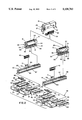
FIG. 2 an exploded assembly view of the connector and cable positioning and testing components of the modular connector press of FIG. 1, with the prime mover and frame of the press removed for clarity;
FIG. 3 is a sectional view taken along line 3--3 of FIG. 1;
FIG. 4 is a fragmentary sectional view taken along line 4--4 of FIG. 3;
FIG. 5 is a fragmentary top view of the cable tray assembly positioning surface of the modular connector press of FIG. 1 showing the loading position of the right cable tray assembly;
FIG. 6 is the same view as FIG. 5 showing the termination position of the right cable tray assembly;
FIG. 7 is the same view as FIG. 5 showing the loading position of joined left and right cable tray assemblies;
FIG. 8 is the same view as FIG. 5 showing the termination position of joined left and right cable tray assemblies;
FIG. 9 is a fragmentary sectional view taken along line 9--9 of FIG. 3;
FIG. 10 is a fragmentary sectional view taken along line 10--10 of FIG. 3;
FIG. 11 is a fragmentary sectional view taken along line 11--11 of FIG. 3;
FIG. 12 is a fragmentary sectional view taken along line 12--12 of FIG. 6;
FIG. 13 is a fragmentary sectional view taken along line 13--13 of FIG. 6;
FIG. 14 is a fragmentary sectional view taken along line 14--14 of FIG. 3; and
FIG. 15 is a top view of the cable tray assembly positioning surface showing a selection of the unlimited number of different connector harnesses that can be constructed with the modular connector press of the present invention.
DESCRIPTION OF THE PREFERRED EMBODIMENT
A modular connector press embodying the concept of the present invention is designated generally by the numeral 20 in the accompanying drawings. Press 20 includes standard electrical, pneumatic or other mechanisms for reciprocating a press ram 21 with sufficient force to terminate a connector to a multiconductor flat cable 22. As seen in FIG. 2, ram 21 includes a pair of toggle clamps 23 that include latching links 24 that engage slots 25 formed on connector test heads 26 or 27 to releasably secure connector test heads 26 or 27 to ram 21.
As best seen in FIG. 2, connector test heads are illustrated for two types of connectors, a socket connector test head 26 and a card edge connector test head 27. Both connector test heads are constructed as modular units that can be quickly, easily and interchangeably mounted to ram 21. Test heads 26 and 27 both include a plurality of contact pins 28 that project from an upper surface of each test head, pins 28 being disposed to mate with a socket connector 29 that is connected to the electronic test circuitry (not shown) of the press by a shielded flat cable 30. Located on either side of pins 28 are mounting bores 31 that accept dowel pins 32 projecting from the lower surface of ram 21 to align and help secure test heads 26 or 27 to ram 21.
Test heads 26 and 27 also both present resiliently mounted left and right nylon plastic insulators 33 and 34 that each mount left and right signal emitting brass ram bars 35 and 36. Insulators 33 and 34 are carried by pins 44 that are resiliently mounted in each test head 26 and 27, allowing resilient engagement of ram bars 35 and 36 with cable 22 when ram 21 is extended. Insulators 33 and 34 are formed of a dielectric material to prevent conduction of the signal applied to ram bars 35 and 36 to any other part of press 20. Ram bars 35 and 36 are each disposed over and are aligned with left and right brass signal emitting track bars 37 and 38. Track bars 37 and 38 are electrically connected to the press test circuitry through a cable (not shown) to receive an oscillating test signal for application to multi-conductor flat cable 22 of an assembled harness to be tested. Ram bars 35 and 36 each present a resilient contacts 39 formed at a rear end of each bar and disposed to contact a rear end portion of each respective track bar 37 or 38 when a test head is in its extended termination position such that the signal applied to track bars 37 or 38 is conducted to and emitted by each respective ram bar 35 or 36.
Socket connector test head 26 is specially configured to terminate and test a lateral entry socket connector 40 by providing a plurality of resiliently mounted test pins 41 which are each conductively connected to one of contact pins 28 for insertion into each contact of socket connector 40 during termination of connector 40 to cable 22.
Card edge connector test head 27 is specially configured to terminate and test a card edge connector 42 by providing a circuit board 43 specially configured to mate with a card edge connector 42 during the termination of connector 42 to cable 22. Circuit board 43 includes a plurality of circuits conductively connected to contact pins 28 to conductively connect each contact of card edge connector 42 to the test circuitry of press 20. Circuit board 43 is secured within card edge connector test head 27 by screw fasteners 45 which allow easy removal of circuit board 43. Circuit board 43 is provided in a selection of different sizes corresponding to the number of contacts of the card edge connectors 42 to be terminated and tested in press 20. Thus card edge connector test head 26 is easily configured for a particular size of card edge connector 42 by securing the proper size circuit board 43 in test head 2 with fasteners 45.
Although all possible variations are not shown in the drawings, the present invention contemplates the use of a variety of modular interchangeable test heads that can be quickly exchanged to allow the termination and testing of a variety of different styles of connectors to a wire harness. For example, test heads could be specially adapted to test and terminate D-subminiature connectors, header connectors, dual in-line pin connectors and ribbon connectors.
The test circuitry for determining whether a terminated harness is faulty due to open or short circuits between adjacent conductive paths in the assembled harness is identical to that described in U.S. Ser. No. 07/521,623, filed May 9, 1990 which is incorporated herein by reference. The test circuitry includes test signal means for capacitively inducing an oscillatory signal in the conductor of a wire of the conductive path to be tested by applying the signal to either left or right track bars 37 or 38, depending upon the side of the harness to be tested, which in turn conducts the signal through contact 39 to the respective ram bars 35 or 36, and electrical continuity test means connected by shielded flat cable 30 to either socket connector test head 26 or card edge connector test head 27 which is conductively engaged with each respective conductive path of the harness through test pins 41 or card edge circuit board 43, for measuring the amplitude of the oscillatory signal at the connector outlet of each conductive path to be tested and comparing the measured amplitude to a predetermined amplitude value and for providing a fault signal indicative of the condition of the conductive path to be tested when the measured amplitude is equal to the predetermined amplitude value.
As best seen in FIG. 2, press 20 includes interchangeable left and right tray assemblies 48 and 49 and interchangeable connector tracks 50 and 51 which are respectively configured to position lateral entry socket connector 40 and card edge connector 42 for termination to flat cable 22.
Left and right tray assemblies 48 and 49 are constructed as separable mirror image assemblies that can be used individually or secured by a locking pin 53 to be used as a unit depending upon the type of harness under construction. Tray assemblies 48 and 49 are constructed to individually or commonly engage the surface of press 20 for accurate sliding translation in a direction parallel to the length of ram 21 for advancement into an aligned position underneath press ram 21. Both tray assemblies 48 and 49 include main body 54 that movably mounts flat cable positioning trays 55 for translation in a direction perpendicular to the direction of advancement of the tray assemblies in the press. Adjustment knob 57 projecting from slot 58, as seen in FIG. 10, can be tightened to secure each tray 55 in one position relative to each main body portion 54. Each main body 54 includes a connector pusher. 56 disposed to align with slot 68 in tracks 50 and 51 to engage a connector and push it inwardly a the tray assembly is translated inwardly. An indicia scale 60 is provided on each main body 54 to facilitate accurate positioning of each tray 55.
Each tray 55 includes a plurality of connector positioning slots 61 formed on the surface of tray 55 parallel to the direction of advancement of each tray. Each slot 61 is formed with a width to accept the type of connector to be positioned in the slot. For example, slots 61 of trays 55 can be sized to accept and accurately position socket connector 40 or card edge connector 42. An adjustable cable guide 62 is slidably mounted on each tray 55 to accurately position a flat cable 22 between guide 62 and tray edge 63. Connector positioning slots 64 are formed in tray edge 63 to accept and position connectors. Guide positioning slots 65 are provided on the surface of tray 55 to accept an edge of guide 62 and resiliently latch guide 62 in a number of predetermined positions corresponding to the different standard sizes of connectors to be terminated in press 20. Cable guide 62 positions cable 22 and prevents twisting of cable 22 as tray assemblies 48 or 49 are advanced beneath press ram 21. Cable guide 62 includes a plurality of connector positioning slots 66 disposed opposite connector positioning slots 64 that are aligned with corresponding slots 61 on trays 55.
Interchangeable connector tracks 50 and 51 include guide slots 67 that engage flanges in the main body 54 of trays 48 and 49 to accurately guide the position of trays under ram 21. Tracks 50 and 51 present a connector positioning slot 68 extending the length of each track. A plurality of holes 69 formed on each edge of tracks 50 and 51 accept pins 70 of cable stop 71 to interchangeably mount stop 71 to position the distal end of cable 22. Stop 71 is configured to offset the distal edge of a flat cable 22 brought into abutment therewith relative to the position of a connector in tracks 50 and 51 to produce either flush or recessed orientation of the distal edge of cable 22 relative to a terminated connector. Rotation of stop 71 180 degrees changes the position of stop 71 from the flush to the recessed orientation.
Left and right track bars 37 and 38 are positioned at the inner, upper surface of tracks 50 and 51 on either side of the connector positioning slot 68. Tracks 50 and 51 are formed of a dielectric material to prevent the conduction of the test signal applied to track bars 37 and 38 to any other part of the press 20.
As seen in FIGS. 3 and 4, a track connector stop 72 is positioned in slot 68 of tracks 50 or 51 to stop and position a connector underneath ram 21 Track connector stop 72 includes a sensor switch (not shown) which provides an output to the press control circuitry to indicate a connector is in the track in the proper position underneath ram 21 for actuation of ram 21.
As best seen in FIG. 12, connectors 40 and 42 are stripped from test heads 26 or 27 by engagement of structural edges of each connector with first stripping edge 73 formed on the forward end of track connector stop 72 and a second stripping edge 74 formed on the distal end of connector pusher 56 of each tray assembly 48 or 49. When a tray assembly is advanced underneath ram 21 it drives a connector inwardly against track connector stop 72 trapping the connector between first and second stripping edges 73 and 74 which secure the connector against upward movement to prevent movement of the connector when ram 21 and test heads 26 or 27 are withdrawn after termination and testing is completed.
As best seen in FIG. 1, the position of tracks 50 or 51 with respect to ram 21 is adjustable by securing a track positioning pin 75 within one a of plurality of detents (not shown) disposed along the length of each track to accurately position a track for a specific width of connector. Thus a track can be adjusted to accurately center connectors of different widths with respect to ram 21, when each connector is brought into abutment with track connector stop 72 carried on the track, to provide an even application of force across the width of the connector during termination. A linear potentiometer (not shown) connected to the press control circuitry senses the position of track 50 or 51 to ensure proper positioning of a connector relative to ram 21.
Left and right tray assemblies 48 and 49 can be quickly configured to be used individually, see FIGS. 5 and 6, to apply a connector to a harness by either a left or right handed operator or can be quickly configured to operate as a unit as seen in FIGS. 7 and 8, by securing left and right tray assemblies 48 and 49 together with locking pin 53, positioning connectors already terminated to a flat cable in slots 61 and adjusting the relative positions of trays 55, to allow the accurate application of a connector between the connectors already terminated to the flat cable.
As depicted in FIG. 15, the modular construction of tray assemblies 48 and 49 and the adjustability of trays 55 allow the construction of a great variety of different harnesses. A representative number of harnesses are illustrated in FIG. 15 including a socket-card edge-socket harness 76, a card edge-socket-card edge harness 77, and various configurations of socket connector harnesses of varying numbers of circuits illustrated by harnesses 78 through 82. These harnesses are only representative of the great variety of different combinations of connectors and connector positions in a harness that can be constructed by the present invention.
To construct a harness of a particular type of connector tray assemblies 48 and 49 and tracks 50 or 51 must be selected to match the connector type to slot 68 and match the connector selected to fit slots 61 of trays 55. Tray assemblies for different types of connectors can be fastened together with locking pin 53 and moved as a unit to accurately position different types of connectors positioned within slots 61 of each tray 55 for intermediate termination of a third connector, which by the selection of the appropriate type of track 55 and test head 26 or 27, can be of a third type of connector. For termination of a third connector between two connectors harness stop 70 is removed and each tray 55 is adjusted and locked in place by adjustment knob 57 in the direction transverse to the direction of translation of tray assemblies 48 an 49 to accurately position the line along cable 22, relative to ram 21, where it is desired to terminate the third connector.
Press 20 by the provision of the interchangeable modular test heads 26 and 27 and the interchangeable and adjustable tray assemblies and tracks provides for an extremely versatile press that can accurately position connectors relative to the length of the cable, terminate the connectors to the cable and test the harnesses for electrical faults.