US5134606A - Method and optical recording/reproducing apparatus for optimizing laser beam power - Google Patents
Method and optical recording/reproducing apparatus for optimizing laser beam power Download PDFInfo
- Publication number
- US5134606A US5134606A US07/549,986 US54998690A US5134606A US 5134606 A US5134606 A US 5134606A US 54998690 A US54998690 A US 54998690A US 5134606 A US5134606 A US 5134606A
- Authority
- US
- United States
- Prior art keywords
- recording
- signal
- laser beam
- power
- optimal
- Prior art date
- Legal status (The legal status is an assumption and is not a legal conclusion. Google has not performed a legal analysis and makes no representation as to the accuracy of the status listed.)
- Expired - Lifetime
Links
Images


Classifications
-
- G—PHYSICS
- G11—INFORMATION STORAGE
- G11B—INFORMATION STORAGE BASED ON RELATIVE MOVEMENT BETWEEN RECORD CARRIER AND TRANSDUCER
- G11B7/00—Recording or reproducing by optical means, e.g. recording using a thermal beam of optical radiation by modifying optical properties or the physical structure, reproducing using an optical beam at lower power by sensing optical properties; Record carriers therefor
- G11B7/12—Heads, e.g. forming of the optical beam spot or modulation of the optical beam
- G11B7/125—Optical beam sources therefor, e.g. laser control circuitry specially adapted for optical storage devices; Modulators, e.g. means for controlling the size or intensity of optical spots or optical traces
- G11B7/126—Circuits, methods or arrangements for laser control or stabilisation
-
- G—PHYSICS
- G11—INFORMATION STORAGE
- G11B—INFORMATION STORAGE BASED ON RELATIVE MOVEMENT BETWEEN RECORD CARRIER AND TRANSDUCER
- G11B11/00—Recording on or reproducing from the same record carrier wherein for these two operations the methods are covered by different main groups of groups G11B3/00 - G11B7/00 or by different subgroups of group G11B9/00; Record carriers therefor
- G11B11/10—Recording on or reproducing from the same record carrier wherein for these two operations the methods are covered by different main groups of groups G11B3/00 - G11B7/00 or by different subgroups of group G11B9/00; Record carriers therefor using recording by magnetic means or other means for magnetisation or demagnetisation of a record carrier, e.g. light induced spin magnetisation; Demagnetisation by thermal or stress means in the presence or not of an orienting magnetic field
- G11B11/105—Recording on or reproducing from the same record carrier wherein for these two operations the methods are covered by different main groups of groups G11B3/00 - G11B7/00 or by different subgroups of group G11B9/00; Record carriers therefor using recording by magnetic means or other means for magnetisation or demagnetisation of a record carrier, e.g. light induced spin magnetisation; Demagnetisation by thermal or stress means in the presence or not of an orienting magnetic field using a beam of light or a magnetic field for recording by change of magnetisation and a beam of light for reproducing, i.e. magneto-optical, e.g. light-induced thermomagnetic recording, spin magnetisation recording, Kerr or Faraday effect reproducing
- G11B11/10502—Recording on or reproducing from the same record carrier wherein for these two operations the methods are covered by different main groups of groups G11B3/00 - G11B7/00 or by different subgroups of group G11B9/00; Record carriers therefor using recording by magnetic means or other means for magnetisation or demagnetisation of a record carrier, e.g. light induced spin magnetisation; Demagnetisation by thermal or stress means in the presence or not of an orienting magnetic field using a beam of light or a magnetic field for recording by change of magnetisation and a beam of light for reproducing, i.e. magneto-optical, e.g. light-induced thermomagnetic recording, spin magnetisation recording, Kerr or Faraday effect reproducing characterised by the transducing operation to be executed
- G11B11/10504—Recording
-
- G—PHYSICS
- G11—INFORMATION STORAGE
- G11B—INFORMATION STORAGE BASED ON RELATIVE MOVEMENT BETWEEN RECORD CARRIER AND TRANSDUCER
- G11B11/00—Recording on or reproducing from the same record carrier wherein for these two operations the methods are covered by different main groups of groups G11B3/00 - G11B7/00 or by different subgroups of group G11B9/00; Record carriers therefor
- G11B11/10—Recording on or reproducing from the same record carrier wherein for these two operations the methods are covered by different main groups of groups G11B3/00 - G11B7/00 or by different subgroups of group G11B9/00; Record carriers therefor using recording by magnetic means or other means for magnetisation or demagnetisation of a record carrier, e.g. light induced spin magnetisation; Demagnetisation by thermal or stress means in the presence or not of an orienting magnetic field
- G11B11/105—Recording on or reproducing from the same record carrier wherein for these two operations the methods are covered by different main groups of groups G11B3/00 - G11B7/00 or by different subgroups of group G11B9/00; Record carriers therefor using recording by magnetic means or other means for magnetisation or demagnetisation of a record carrier, e.g. light induced spin magnetisation; Demagnetisation by thermal or stress means in the presence or not of an orienting magnetic field using a beam of light or a magnetic field for recording by change of magnetisation and a beam of light for reproducing, i.e. magneto-optical, e.g. light-induced thermomagnetic recording, spin magnetisation recording, Kerr or Faraday effect reproducing
- G11B11/10595—Control of operating function
-
- G—PHYSICS
- G11—INFORMATION STORAGE
- G11B—INFORMATION STORAGE BASED ON RELATIVE MOVEMENT BETWEEN RECORD CARRIER AND TRANSDUCER
- G11B7/00—Recording or reproducing by optical means, e.g. recording using a thermal beam of optical radiation by modifying optical properties or the physical structure, reproducing using an optical beam at lower power by sensing optical properties; Record carriers therefor
- G11B7/004—Recording, reproducing or erasing methods; Read, write or erase circuits therefor
Definitions
- This invention relates to an optical recording/reproducing apparatus and more particularly, to a magnetooptic recording/reproducing apparatus which records or reproduces an information signal by a laser beam onto or from a rotating magnetooptic disc.
- an object of this invention is to provide a magnetooptic recording/reproducing apparatus having a simple structure, which is capable of recording information with the recording laser beam having an optimal power irrespective of a track position on a magnetooptic disc.
- a magnetooptic recording/reproducing apparatus comprising means for recording for one track a recording signal with a recording laser beam of which power changes stepwise, means for reading out the recording signal corresponding to the stepwise changed power, means for obtaining an optimal power level of the recording laser beam by evaluating the read-out signal, means for recording an information signal by utilizing thus obtained optimal recording beam power from the track, and means for correcting the recording laser beam power correspondingly to the shift of a recording position on a disc.
- the optimizing process to obtain an optimal recording laser beam power is repeated.
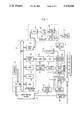
- FIG. 1 is a block diagram of an embodiment according to the present invention.
- FIG. 2(a) shows a waveform of a recording signal having a stepwise changed power according to the present invention
- FIG. 2(b) shows a waveform of an error output delivered from an error amplifier in FIG. 1;
- FIG. 2(c) shows sampling times for sampling the error output shown in FIG. 2(b);
- FIGS. 3(a), 3(b) and 3(c) are charts to show relationships among various recording laser beam powers, pit states formed on a disc and reproduced signals;
- FIG. 4 shows an operation sequence for obtaining an optimal recording laser beam power according to the present invention
- FIG. 5 shows examples of characteristic curves showing relation between line velocity and a necessary recording laser beam power
- FIG. 6 is a flow chart to show the processing flow to obtain an optimal recording laser beam power according to the present invention.
- an embodiment of the present invention comprises a magnetooptic disc 1, an optical head 2 which contains a laser diode to emit a laser beam onto the disc 1 in order to record or reproduce an information signal, a positioner motor 3 which moves the optical head 2 to a designated position in the radial direction of the disc 1, a spindle motor 4 which turns the disc 1, and a magnetic field generator 5 which provides an auxiliary magnetic field to the disc 1.
- a video signal as the information signal to be recorded is inputted to a modulator 7 via a terminal 6 to be subjected to a prescribed modulation, and then supplied to the optical head 2 via a recording amplifier 8.
- a reproduced signal from the head 2 is supplied to a signal processing circuit 10 via an RF amplifier 9.
- the output from the RF amplifier 9 is also fed to an evaluation circuit 11 which evaluates suitability of recorded pits on the disc 1, i.e., suitability of the reproduced signal.
- the output from the evaluation circuit 11 is fed to a system control section 12.
- the evaluation circuit 11 will be described hereinafter in detail.
- the system control section 12 controls the apparatus of the embodiment as a whole based on an input command from a controller 13, and computes an optimal intensity (power) of the recording laser beam so as to control an amplifying factor of the recording amplifier 8.
- a servo control section 14 is connected to the system control section 12 via an I/O and receives instructions from the control section 12 in order to execute operation designated by the controller 13.
- the servo control section 14 also receives a tracking error signal and a focus error signal from the optical head 2 and, thus, controls the positioner motor 3, the spindle motor 4 and a coil actuater 17 mounted on the optical head 2 via a servo section 15 and a drive amplifier 16 to perform the designated operation.
- recording usually begins from a track which is preset.
- the operation for obtaining the optimal laser beam power is initially conducted whenever the recording operation begins. More particularly, under the control of a CPU 29, the system control section 12 outputs to an output port 19 power data which stepwise changes in seven stages on the basis of an initial data.
- the initial data is stored in advance in a read only memory (ROM) 33 and transferred into a random access memory (RAM) 18 when the apparatus of the embodiment is energized.
- ROM read only memory
- RAM random access memory
- the power data from the output port 19 is added by an adder 20 to correction data (to be described in detail hereinafter) which is determinable depending on a position of the optical head 2, i.e., a track position on the disc, the sum of which is sent to a D/A converter 21 and converted into an analog signal.
- the analog signal from the D/A converter 21 is supplied to the recording amplifier 8 where the modulation signal from the modulator 7 is amplified up to this added power data level and supplied to the optical head 2.
- FIG. 2(a) shows a recording signal outputted from the recording amplifier 8 wherein an NRZ (non return to zero) code input signal is modulated by the modulator 9 into an NRZI (non return to zero inverted) code recording signal. As shown in FIG.
- the recording signal has seven amplitudes stepwise changed for one track.
- the repetitive frequency of the recording signal corresponding to the data transfer rate is about 50 MHz in this embodiment.
- respective recording tracks on the disc have a period of about 16.7 ms.
- the recording signal changes for every period of about 2 ms, and has a step size of about 0.4 mW.
- the magnetooptic disc 1 rotates at the rate of 3,600 rpm.
- any signal as the modulation signal may be supplied to the terminal 6 because the content of the modulation signal is not related to the optimization process.
- the system control section 12 sends the power data which stepwise changes in the seven steps to the output port 19, the seven power data corresponding to the respective steps are stored into another memory area of the RAM 18.
- the servo control section 14 brings back the optical head 2 to the starting point of this track, and the track is scanned with a reading laser beam having a given power which is weaker than that of the recording laser beam.
- a reproduced signal having a level corresponding to the magnetization state on the disc is picked up by the optical head 2 and amplified by the RF amplifier 9 to be supplied to the evaluation circuit 11.
- the reproduced signal is sent to positive and negative peak detection circuits 23 and 24 via a capacitor 22, and positive and negative peaks are detected, respectively.
- An error detection amplifier 25 outputs the difference between the positive and negative peaks.
- an inverter 26 is inserted between the negative peak detection circuit 24 and the error detection amplifier 25.
- the error output from the error detection amplifier 25 is converted into digital data by an A/D converter 27, and supplied to the system control section 12 via an input port 28.
- FIGS. 3(a), (b) and (c) are charts showing the relationships of the recording laser beam power, the pit state formed on the disc surface and the reproduced signal.
- FIG. 3(a) shows the case where the recording laser beam power is low
- FIG. 3(b) where the recording laser beam power is at an optimal level
- FIG. 3(c) where the recording laser beam power is excessive.
- the recording signal of the NRZI code is classified as a mark length recording method and, therefore, the harmonic distortion changes depending on the recording laser beam power. If the recording laser beam power is optimal, the harmonic distortion becomes minimal (about -40 dB). At this time, the average value of the reproduced signal coincides with the center level in the amplitude thereof. But if the power is smaller or greater than the optimal level, the average value of the reproduced signal does not coincide with the center level. This means that even harmonic distortion occurs and the average value of the reproduced signal would include a direct current component corresponding to the even harmonic distortion.
- FIG. 2(b) shows a waveform of the error output from the error detection amplifier 25 and the error output changes around the average value (ground value) corresponding to the changes of the recording laser beam power shown in FIG. 2(a).
- the error data inputted via the input port 28 is picked up at the sampling timing of FIG. 2(c) under the control of the CPU 29, and stored in another memory area of the RAM 18.
- the CPU 29 starts the computation operation to obtain a optimal recording laser beam power.
- the CPU 29 computes optimal power data which makes error data zero by the least squares method or the like, based on the seven power data and the seven error data stored in the RAM 18, and outputs the computed optimal power data to the output port 19.
- the computed optimal power data is stored in the RAM 18 as the initial data to be updated.
- the routine recording operation starts to record information.
- FIG. 4 shows the sequence of the operations.
- the system control section 12 increases or decreases the initial data by an amount corresponding to four steps (equivalent to 1.6 mW) to form again power data having seven steps and records a modulation signal which is level-modified by the power data on the same track to repeat the operation for obtaining the optimal recording laser beam power.
- the optical head 2 in addition to the optical head 2, there is provided another optical head 30 at a position apart from the head 2 by 90 degrees so that erasing operation can be performed simultaneously with the recording/reproducing operation. The optical head 2 is returned to the starting point of the track after the optimal recording laser beam power has been obtained, and the routine recording operation with the obtained optimal power starts.
- the recording track is arranged from the inner side to outer side in spiral form and, thus, the recording position shifts from the inner side to the outer side.
- the optimal recording laser beam power obtained by the optimization process is the optimal level for the position where the recording operation starts. Therefore, as the recording operation proceeds over a plurality of tracks, the recording position shifts from the start track to another track positioned at more outer side on the disc and the recording laser beam power which was set as optimal at the beginning becomes not necessarily optimal any more.
- the magnetooptic disc rotates at a predetermined rate, the line velocity at a recording position changes due to the change in radial distance.
- a greater recording laser beam power becomes necessary.
- the present invention automatically corrects or compensates for an optimal recording laser beam power as the recording position shifts outward.
- the position sensor 31 comprises, for example, a linear encoder which measures the radial distance of the optical head 2 from the center, and a counter which outputs the positional data corresponding to the output from the linear encoder.
- the output from the position sensor 31 is fed to a correction data converter 32 to be converted into prescribed correction data corresponding to the head position, which in turn is added to the output from the output port 19 by the adder 20.
- the correction data will now be described.
- the optimal recording laser beam power is known to be proportionate to the line velocity raised to the power of ⁇ . ⁇ varies in the range from 0.6 to 1.3 depending on the types of the disc.
- the correction data converter 32 generates correction data which is determinable in advance by the type of disc used, and comprises a read only memory (ROM) or the like which facilitates storing of correction data corresponding to plural ⁇ s.
- ROM read only memory
- the ROM 33 further stores a control program for the magnetooptic recording/reproducing apparatus and the operation proceeds in accordance with the program under the commands from the controller 13.
- FIG. 6 is a flow chart showing the processing steps for obtaining the optimal power of the recording laser beam.
- a magnetooptic recording/reproducing apparatus having a simple structure and capable of optimally recording can be provided by using a test recording signal having a stepwise changed recording power to obtain an optimal recording laser beam power and by correcting or compensating the optimal recording laser beam power according to outward shift of an optical head.
- the present invention can precisely control a recording laser beam power adaptively to change in the recording position on the disc and change in recording sensitivity of a magnetooptic recording disc and, thus, can maintain an optimal recording condition, and a low error rate.
Abstract
Description
Claims (12)
Applications Claiming Priority (6)
| Application Number | Priority Date | Filing Date | Title |
|---|---|---|---|
| JP1174110A JP2800281B2 (en) | 1989-07-07 | 1989-07-07 | Optical recording / reproducing device |
| JP1-174110 | 1989-07-07 | ||
| JP1230807A JPH0393047A (en) | 1989-09-05 | 1989-09-05 | Optical recording and reproducing device |
| JP1-230807 | 1989-09-05 | ||
| JP1250744A JPH03113841A (en) | 1989-09-28 | 1989-09-28 | Optical recording and reproducing device |
| JP1-250744 | 1989-09-28 |
Publications (1)
| Publication Number | Publication Date |
|---|---|
| US5134606A true US5134606A (en) | 1992-07-28 |
Family
ID=27323891
Family Applications (1)
| Application Number | Title | Priority Date | Filing Date |
|---|---|---|---|
| US07/549,986 Expired - Lifetime US5134606A (en) | 1989-07-07 | 1990-07-09 | Method and optical recording/reproducing apparatus for optimizing laser beam power |
Country Status (1)
| Country | Link |
|---|---|
| US (1) | US5134606A (en) |
Cited By (23)
| Publication number | Priority date | Publication date | Assignee | Title |
|---|---|---|---|---|
| US5233584A (en) * | 1990-09-04 | 1993-08-03 | International Business Machines Corporation | Optical disk device using high and low data-sensing criteria plus device recalibration for error control |
| US5249172A (en) * | 1991-03-19 | 1993-09-28 | Matsushita Electric Industrial Co., Ltd. | Write laser power setting responsive to a series of written test signals having two frequency components |
| US5268893A (en) * | 1991-10-18 | 1993-12-07 | International Business Machines Corporation | Write power calibration utilizing least squares fit of read-back signals for moving media memory |
| US5309419A (en) * | 1992-02-14 | 1994-05-03 | Sony Corporation | M-O disk recording apparatus with light amount control based on multiple test performed on a test region at multiple disk rotational velocities |
| US5355360A (en) * | 1992-04-10 | 1994-10-11 | Konica Corporation | Semiconductor laser controlling apparatus |
| US5475666A (en) * | 1992-03-04 | 1995-12-12 | Mitsubishi Denki Kabushiki Kaisha | Optically modulated overwritable recording device |
| US5491681A (en) * | 1993-12-13 | 1996-02-13 | I M P, Inc. | Peak detector for amplitude modulated signals |
| US5586099A (en) * | 1995-05-22 | 1996-12-17 | International Business Machines Corporation | Optimized laser read power based upon scan speed of optical medium and erasure characteristics of the medium |
| EP0753847A2 (en) * | 1995-07-10 | 1997-01-15 | Fujitsu Limited | Magneto-optical disk drive supporting a direct-over-write operation and a write-after-erase operation |
| US5625615A (en) * | 1995-12-08 | 1997-04-29 | International Business Machines Corporation | Optical storage drive employing variable write speed for reduced laser write power |
| US6078444A (en) * | 1995-05-12 | 2000-06-20 | Cirrus Logic, Inc. | Read channel auxiliary high precision data conversion |
| WO2001015148A1 (en) * | 1999-08-20 | 2001-03-01 | Teac Corporation | Optical disk drive unit |
| US20020044512A1 (en) * | 2000-10-10 | 2002-04-18 | Tdk Corporation | Optical recording medium and method |
| DE10064775A1 (en) * | 2000-12-22 | 2002-06-27 | Thomson Brandt Gmbh | Method for controlling the light power of a scanning beam in an optical device for reading or writing of an optical data medium, such as a DVD, so that faster reading or writing is obtained |
| EP1283520A2 (en) * | 2001-08-07 | 2003-02-12 | Mitsumi Electric Company Ltd. | Optical disc drive |
| US6538968B1 (en) * | 1996-10-08 | 2003-03-25 | Sanyo Electric Co, Ltd. | Information recording/reproducing apparatus |
| EP1320089A2 (en) | 2001-12-11 | 2003-06-18 | Yamaha Corporation | Optical disk apparatus of variable recording velocity with optimum power control |
| US6600715B2 (en) * | 2000-09-20 | 2003-07-29 | Sharp Kabushiki Kaisha | Optical reproducing device and control method thereof |
| US6714503B1 (en) * | 1998-04-03 | 2004-03-30 | Samsung Electronics Co., Ltd. | Adaptive recording method and apparatus for high-density optical recording apparatus |
| US6775216B2 (en) | 2000-08-29 | 2004-08-10 | Zoran Corporation | Method and apparatus for restarting a write operation in a disk drive system |
| US20040196772A1 (en) * | 2000-02-03 | 2004-10-07 | Samsung Electronics Co., Ltd. | Laser diode driver, method of driving the laser diode driver, and method of initializing an optical recording and reproducing apparatus |
| US20060278609A1 (en) * | 2003-05-16 | 2006-12-14 | Applied Materials, Inc. | Method of determining wafer voltage in a plasma reactor from applied bias voltage and current and a pair of constants |
| EP1351225A3 (en) * | 2002-03-22 | 2007-01-03 | Yamaha Corporation | Optical disc recording method and optical disc recording apparatus |
Citations (5)
| Publication number | Priority date | Publication date | Assignee | Title |
|---|---|---|---|---|
| US4769802A (en) * | 1984-06-07 | 1988-09-06 | Victor Company Of Japan, Ltd. | Information recording medium disc and method and apparatus for recording/reproducing information using the disc |
| US4866692A (en) * | 1986-08-22 | 1989-09-12 | Hitachi, Ltd. | Method and apparatus for information recording and reproduction of a pit-shape-forming optical recording type |
| US4982397A (en) * | 1987-11-30 | 1991-01-01 | Kabushiki Kaisha Toshiba | Apparatus for focusing a light beam onto an information memory medium having a data non-storage area |
| US4982389A (en) * | 1987-01-30 | 1991-01-01 | Hitachi, Ltd. | Magneto-optical recorder with compensation for variation in applied magnetic field intensity on a recording medium |
| US5005164A (en) * | 1987-04-28 | 1991-04-02 | Sharp Kabushiki Kaisha | Recording and reproducing apparatus |
-
1990
- 1990-07-09 US US07/549,986 patent/US5134606A/en not_active Expired - Lifetime
Patent Citations (5)
| Publication number | Priority date | Publication date | Assignee | Title |
|---|---|---|---|---|
| US4769802A (en) * | 1984-06-07 | 1988-09-06 | Victor Company Of Japan, Ltd. | Information recording medium disc and method and apparatus for recording/reproducing information using the disc |
| US4866692A (en) * | 1986-08-22 | 1989-09-12 | Hitachi, Ltd. | Method and apparatus for information recording and reproduction of a pit-shape-forming optical recording type |
| US4982389A (en) * | 1987-01-30 | 1991-01-01 | Hitachi, Ltd. | Magneto-optical recorder with compensation for variation in applied magnetic field intensity on a recording medium |
| US5005164A (en) * | 1987-04-28 | 1991-04-02 | Sharp Kabushiki Kaisha | Recording and reproducing apparatus |
| US4982397A (en) * | 1987-11-30 | 1991-01-01 | Kabushiki Kaisha Toshiba | Apparatus for focusing a light beam onto an information memory medium having a data non-storage area |
Cited By (33)
| Publication number | Priority date | Publication date | Assignee | Title |
|---|---|---|---|---|
| US5233584A (en) * | 1990-09-04 | 1993-08-03 | International Business Machines Corporation | Optical disk device using high and low data-sensing criteria plus device recalibration for error control |
| US5249172A (en) * | 1991-03-19 | 1993-09-28 | Matsushita Electric Industrial Co., Ltd. | Write laser power setting responsive to a series of written test signals having two frequency components |
| US5268893A (en) * | 1991-10-18 | 1993-12-07 | International Business Machines Corporation | Write power calibration utilizing least squares fit of read-back signals for moving media memory |
| US5309419A (en) * | 1992-02-14 | 1994-05-03 | Sony Corporation | M-O disk recording apparatus with light amount control based on multiple test performed on a test region at multiple disk rotational velocities |
| US5475666A (en) * | 1992-03-04 | 1995-12-12 | Mitsubishi Denki Kabushiki Kaisha | Optically modulated overwritable recording device |
| US5355360A (en) * | 1992-04-10 | 1994-10-11 | Konica Corporation | Semiconductor laser controlling apparatus |
| US5491681A (en) * | 1993-12-13 | 1996-02-13 | I M P, Inc. | Peak detector for amplitude modulated signals |
| US5581536A (en) * | 1993-12-13 | 1996-12-03 | Imp, Inc. | Mass storage servo control system utilizing an analog signal leak detector |
| US6078444A (en) * | 1995-05-12 | 2000-06-20 | Cirrus Logic, Inc. | Read channel auxiliary high precision data conversion |
| US5586099A (en) * | 1995-05-22 | 1996-12-17 | International Business Machines Corporation | Optimized laser read power based upon scan speed of optical medium and erasure characteristics of the medium |
| EP0753847A2 (en) * | 1995-07-10 | 1997-01-15 | Fujitsu Limited | Magneto-optical disk drive supporting a direct-over-write operation and a write-after-erase operation |
| EP0753847A3 (en) * | 1995-07-10 | 1997-12-29 | Fujitsu Limited | Magneto-optical disk drive supporting a direct-over-write operation and a write-after-erase operation |
| US5625615A (en) * | 1995-12-08 | 1997-04-29 | International Business Machines Corporation | Optical storage drive employing variable write speed for reduced laser write power |
| US6538968B1 (en) * | 1996-10-08 | 2003-03-25 | Sanyo Electric Co, Ltd. | Information recording/reproducing apparatus |
| US7212310B2 (en) | 1998-04-03 | 2007-05-01 | Samsung Electronics Co., Ltd. | Adaptive recording method and apparatus for high-density optical recording apparatus |
| US20040125729A1 (en) * | 1998-04-03 | 2004-07-01 | Samsung Electronics Co., Ltd. | Adaptive recording method and apparatus for high-density optical recording apparatus |
| US6714503B1 (en) * | 1998-04-03 | 2004-03-30 | Samsung Electronics Co., Ltd. | Adaptive recording method and apparatus for high-density optical recording apparatus |
| KR100447490B1 (en) * | 1999-08-20 | 2004-09-07 | 티아크 가부시키가이샤 | Optical disk drive unit |
| WO2001015148A1 (en) * | 1999-08-20 | 2001-03-01 | Teac Corporation | Optical disk drive unit |
| US6859426B1 (en) | 1999-08-20 | 2005-02-22 | Teac Corporation | Optical disk drive unit |
| US20040196772A1 (en) * | 2000-02-03 | 2004-10-07 | Samsung Electronics Co., Ltd. | Laser diode driver, method of driving the laser diode driver, and method of initializing an optical recording and reproducing apparatus |
| US7133345B2 (en) * | 2000-02-03 | 2006-11-07 | Samsung Electronics Co., Ltd. | Laser diode driver, method of driving the laser diode driver, and method of initializing an optical recording and reproducing apparatus |
| US6775216B2 (en) | 2000-08-29 | 2004-08-10 | Zoran Corporation | Method and apparatus for restarting a write operation in a disk drive system |
| US6600715B2 (en) * | 2000-09-20 | 2003-07-29 | Sharp Kabushiki Kaisha | Optical reproducing device and control method thereof |
| US6956804B2 (en) * | 2000-10-10 | 2005-10-18 | Tdk Corporation | Optical recording medium with recording marks having different states, and method of recording using the optical recording medium |
| US20020044512A1 (en) * | 2000-10-10 | 2002-04-18 | Tdk Corporation | Optical recording medium and method |
| DE10064775A1 (en) * | 2000-12-22 | 2002-06-27 | Thomson Brandt Gmbh | Method for controlling the light power of a scanning beam in an optical device for reading or writing of an optical data medium, such as a DVD, so that faster reading or writing is obtained |
| EP1283520A2 (en) * | 2001-08-07 | 2003-02-12 | Mitsumi Electric Company Ltd. | Optical disc drive |
| EP1283520A3 (en) * | 2001-08-07 | 2003-08-06 | Mitsumi Electric Company Ltd. | Optical disc drive |
| EP1320089A2 (en) | 2001-12-11 | 2003-06-18 | Yamaha Corporation | Optical disk apparatus of variable recording velocity with optimum power control |
| EP1320089A3 (en) * | 2001-12-11 | 2007-09-19 | Yamaha Corporation | Optical disk apparatus of variable recording velocity with optimum power control |
| EP1351225A3 (en) * | 2002-03-22 | 2007-01-03 | Yamaha Corporation | Optical disc recording method and optical disc recording apparatus |
| US20060278609A1 (en) * | 2003-05-16 | 2006-12-14 | Applied Materials, Inc. | Method of determining wafer voltage in a plasma reactor from applied bias voltage and current and a pair of constants |
Similar Documents
| Publication | Publication Date | Title |
|---|---|---|
| US5134606A (en) | Method and optical recording/reproducing apparatus for optimizing laser beam power | |
| EP0393001B1 (en) | Method and apparatus for operating a disk recorder | |
| EP0556046B1 (en) | Recording and reproducing apparatus for optical disk | |
| EP0404249B1 (en) | Method of and device for adjusting recording parameters | |
| US7760597B2 (en) | Optimal recording apparatus and method for determining an optical recording condition | |
| US5029155A (en) | Optical information recording/reproducing apparatus in which recording power is set prior to recording | |
| US5687156A (en) | Calibration of lasers that produce multiple power output levels of emitted radiation | |
| EP0709837A2 (en) | Optical disks and recording/reproduction thereof | |
| KR900007670B1 (en) | Recorded data reproducing apparatus | |
| US7170838B2 (en) | Information recording and reproducing apparatus | |
| US5982714A (en) | Laser beam adjusting for magnetic field modulation overwrite magneto-optical recording device | |
| US20040114482A1 (en) | Disc recorder/reproducer | |
| US5621709A (en) | Tracking servo apparatus | |
| JP2812441B2 (en) | Optical information recording / reproducing device | |
| US6347067B1 (en) | Apparatus and method for adjusting a reference voltage to detect a Traverse signal based on the types of optical medium | |
| US7242651B2 (en) | Disk reproduction device | |
| US6256274B1 (en) | Data erasure preventing method and circuit thereof and optical disc apparatus mounting the same | |
| KR100697173B1 (en) | Optical disk recording/reproducing device employing waveform correction of laser output signal | |
| US5124964A (en) | Focus servo gain setting circuit for optical record disc reproducing apparatus | |
| US6091685A (en) | Optical disc recording/playing apparatus and method for synchronizing recording of new data | |
| JP3510112B2 (en) | Method and apparatus for controlling light output of laser diode | |
| US7327651B2 (en) | Optical disc device | |
| US20040120235A1 (en) | Recording/reproducing apparatus and method for laser power control during CAV recording | |
| US7376054B2 (en) | Disc reproduction device | |
| US5740137A (en) | Servo control method for an opto-magnetic disc |
Legal Events
| Date | Code | Title | Description |
|---|---|---|---|
| AS | Assignment |
Owner name: NEC CORPORATION, JAPAN Free format text: ASSIGNMENT OF ASSIGNORS INTEREST.;ASSIGNORS:SEKIGUCHI, TORU;SASAKI, YOSHIHIRO;REEL/FRAME:005442/0023 Effective date: 19900706 |
|
| STCF | Information on status: patent grant |
Free format text: PATENTED CASE |
|
| FEPP | Fee payment procedure |
Free format text: PAYOR NUMBER ASSIGNED (ORIGINAL EVENT CODE: ASPN); ENTITY STATUS OF PATENT OWNER: LARGE ENTITY |
|
| FPAY | Fee payment |
Year of fee payment: 4 |
|
| FEPP | Fee payment procedure |
Free format text: PAYER NUMBER DE-ASSIGNED (ORIGINAL EVENT CODE: RMPN); ENTITY STATUS OF PATENT OWNER: LARGE ENTITY Free format text: PAYOR NUMBER ASSIGNED (ORIGINAL EVENT CODE: ASPN); ENTITY STATUS OF PATENT OWNER: LARGE ENTITY |
|
| FPAY | Fee payment |
Year of fee payment: 8 |
|
| FPAY | Fee payment |
Year of fee payment: 12 |
|
| AS | Assignment |
Owner name: KONINKLIJKE PHILIPS ELECTRONICS N V, NETHERLANDS Free format text: ASSIGNMENT OF ASSIGNORS INTEREST;ASSIGNOR:NEC CORPORATION;REEL/FRAME:025857/0327 Effective date: 20110126 |