US5042675A - Container pressure release vent - Google Patents
Container pressure release vent Download PDFInfo
- Publication number
- US5042675A US5042675A US07/520,089 US52008990A US5042675A US 5042675 A US5042675 A US 5042675A US 52008990 A US52008990 A US 52008990A US 5042675 A US5042675 A US 5042675A
- Authority
- US
- United States
- Prior art keywords
- fold
- container
- pressure release
- vent
- score
- Prior art date
- Legal status (The legal status is an assumption and is not a legal conclusion. Google has not performed a legal analysis and makes no representation as to the accuracy of the status listed.)
- Expired - Lifetime
Links
Images


Classifications
-
- H—ELECTRICITY
- H01—ELECTRIC ELEMENTS
- H01M—PROCESSES OR MEANS, e.g. BATTERIES, FOR THE DIRECT CONVERSION OF CHEMICAL ENERGY INTO ELECTRICAL ENERGY
- H01M50/00—Constructional details or processes of manufacture of the non-active parts of electrochemical cells other than fuel cells, e.g. hybrid cells
- H01M50/30—Arrangements for facilitating escape of gases
- H01M50/342—Non-re-sealable arrangements
- H01M50/3425—Non-re-sealable arrangements in the form of rupturable membranes or weakened parts, e.g. pierced with the aid of a sharp member
-
- Y—GENERAL TAGGING OF NEW TECHNOLOGICAL DEVELOPMENTS; GENERAL TAGGING OF CROSS-SECTIONAL TECHNOLOGIES SPANNING OVER SEVERAL SECTIONS OF THE IPC; TECHNICAL SUBJECTS COVERED BY FORMER USPC CROSS-REFERENCE ART COLLECTIONS [XRACs] AND DIGESTS
- Y02—TECHNOLOGIES OR APPLICATIONS FOR MITIGATION OR ADAPTATION AGAINST CLIMATE CHANGE
- Y02E—REDUCTION OF GREENHOUSE GAS [GHG] EMISSIONS, RELATED TO ENERGY GENERATION, TRANSMISSION OR DISTRIBUTION
- Y02E60/00—Enabling technologies; Technologies with a potential or indirect contribution to GHG emissions mitigation
- Y02E60/10—Energy storage using batteries
Definitions
- This invention pertains to a novel pressure relief device for a container which is under pressure or becomes pressurized.
- the invention is directed to a pressure relief vent for a battery which, due to adverse chemical reaction, may become pressurized to a hazardous level.
- Pressurized containers are widely used for a number of purposes such as: storage of gases such as oxygen, nitrogen, natural gas and propane; pressure packaging and dispensing consumer products such as paints, lacquers, varnishes, food products, hair spray, deodorants, shaving lather, insecticides and herbicides; and packaging for electrochemical cells.
- the pressurized containers used for pressure packaging and dispensing consumer products are typically aerosol containers which contain a consumer product which is mixed with a propellant gas such as freon or methyl chloride.
- Pressurized containers are potentially dangerous because an explosion can result upon overpressurization. Overpressurization can result when a container is overfilled. More frequently, however, overpressurization occurs when the container and its contents are subjected to elevated temperatures during incineration or by storage at unacceptably high temperatures. Overpressurization can also occur as the result of unwanted chemical reactions taking place within the container. This situation can occur in a sealed storage battery which releases gases internally upon overcharge or overdischarge. To provide a safety measure, lithium batteries are enclosed in a casing which contains a pressure release vent. The vent releases on overpressure and prevents any possibility of accidental explosion. Many lithium batteries utilize sulfur dioxide as an electrolyte component. Such a battery desirably has a vent that releases at pressure above about 350 psi.
- Willis U.S. Pat. No. 3,918,610, Nov. 11, 1975 discloses a safety vent for a pressurized container which comprises an integral concavity in the container wall, an integral hollow bridge interrupting the concavity, and a weakening score line in the container wall extending across the hollow bridge.
- a safety vent for a pressurized container which comprises an integral concavity in the container wall, an integral hollow bridge interrupting the concavity, and a weakening score line in the container wall extending across the hollow bridge.
- the approach set forth by Willis is not entirely satisfactory because consistent quality control is difficult to achieve.
- the wall thickness under the score line is a critical parameter if operation is to reliably take place at a predetermined pressure range.
- Thickness tolerances for proper venting are therefore undesirably small.
- the casing contains a vent which ruptures when internal casing pressure exceeds a given value.
- the vent includes at least one vent-forming rib projecting outwardly from a circular end wall.
- the rib has formed therein a vent-forming groove which extends transversely along a portion of the length of the rib. Thus, the groove ends are spaced a certain predetermined distance from the base of the rib.
- Romero's design has a disadvantage in that the groove does not extend to the rib base on each side, thereby restricting the size of the vent hole that opens when excessive pressure builds up in the casing and a crack propagates in the groove. It is advantageous to have a large vent opening to permit quick release of pressure, and to minimize blockage of the opening due to salts or other impeding particles that may be contained in the container. Romero's reason for having the groove not extend to the bottom of the base is to minimize corrosion (see col. 2, lines 14-31).
- a further problem is that while the pressure release vent is intended to release at pressures of about 450 psig, it is difficult to maintain a high degree of quality control. Unless high quality dies are used, consistent quality control is vulnerable to die wear. In some cases the vent may not release until pressures of 750 psig are reached.
- J. A. Oswald U.S. Pat. No. 4,789,608, Dec. 6, 1988, discloses a pressure venting device for a battery casing which includes two semi-circular concavities extending upwardly from the bottom surface of the casing. Two oppositely disposed bridges interrupt the concavities. Two score lines are disposed laterally and offset inboard from the bridges. Oswald alleges that since the scores are formed in a flat area of the bottom surface of the battery casing and are not affected by subsequent rib stamping procedures, venting will occur consistently at a predetermined pressure range. Oswald emphasizes that quality control is an important objective in forming battery casing pressure venting devices which have a release point within a consistent relatively narrow range.
- the invention is directed to a pressure release vent for a container comprising: (a) a container having a wall; (b) an indentation formed in said wall, the indentation being interrupted by a flat-topped fold which extends across the indentation and reduces the depth of the indentation at a specific location; and (c) a score formed in said fold, the score providing a point of weakness whereby excessive pressure buildup in the container ruptures the container wall at the score location, thereby permitting pressurized gases to escape from the container.
- the container may have a cylindrical wall and at one end thereof a circular planar base, the periphery of which joins with the edge of the cylindrical wall around its circumference.
- the indentation may be formed in the circular base and may be in the form of an annular groove formed in the circular base.
- the annular groove may be radially inboard of the circumference of the base and may have a generally V-shaped cross-section.
- the end of the cylindrical container opposite the base may be closed with a circular planar disk which joins with the free end of the cylindrical wall.
- the fold may extend radially across the annular groove, at an elevation between the bottom and top of the groove or the elevation of the fold may be more than half the height of the groove.
- the annular groove may be interrupted at a location disposed about 180° radially from the fold location to thereby form a hinge which is of the same general elevation as the base.
- the fold may have on each side shoulders which respectively slope downwardly to the base of the V-shaped annular groove on each side of the fold.
- the score may be curved and have a radius of curvature and a centrepoint which are substantially the same as the radius of curvature and centrepoint of the bottom of the V-shaped annular groove.
- the fold may be at an elevation of about 75 percent of the height of the V-shaped groove.
- the shoulders on each side of the fold may be at about a 45° angle to the base.
- the two walls of the V-shaped groove may be at about a 45° angle to the base to give an included angle of about 90°.
- the inboard wall of the V-shaped groove may be at a 45° angle to the base and the outboard wall may be at a 60° angle to the base to give an included angle of 105°.
- the score may have a "U"-shaped cross-section.
- the release vent may include a hinge which tends to focus release forces at the fold and score.
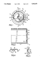
- FIG. 1 illustrates a plan view of the bottom of a container casing
- FIG. 2 illustrates a section view taken along section line A--A of FIG. 1;
- FIG. 3 illustrates a section view taken along section line B--B of FIG. 1;
- FIG. 4 illustrates a section view taken along section line C--C of FIG. 1.
- FIG. 5 illustrates a graph of vent pressure, psi, relative to wall thickness under the groove (total thickness minus groove depth) for two prior art cases
- FIG. 6 illustrates a graph of vent pressure, psi, relative to wall thickness under the groove (total thickness minus groove depth) for the new vent design (BBS PRV);
- FIG. 7 illustrates a graph of groove depth vs. venting for the new vent design.
- FIG. 8 illustrates a graph of pressure (psig) vs. wall deformation for the prior vent design (Patterson, 1985).
- FIG. 9 illustrates a graph of pressure (psig) vs. wall deformation for the new vent design (BBS PRV).
- FIG. 1 illustrates a plan view of the base of a container incorporating the applicant's novel pressure vent design.
- FIG. 1 illustrates a hollow container constructed of a cylindrically shaped container wall 4, which melds with a generally planar circular container base 6 to form a cup. While not shown in FIG. 1, or elsewhere, the end of the container opposite base 6 is closed with a circular disk which mates with the wall 4 to provide a closed container.
- An interrupted annular groove 8 is formed inboard of the container wall 4 and is circumscribed about a centre point 12 of the circular planar container base 6.
- the annular groove 8 is interrupted at one point by a hinge 10, which lies in the same plane as the main part of container base 6.
- the facing ends 11 of the grooves 8 on each side of the hinge 10 are smoothly rounded.
- Vent 14 is disposed in the annular groove 8 opposite to hinge 10. Vent 14 is denoted by a circled area.
- the hinge 10 serves to focus internal vent forces at the vent 14.
- Vent 14 is comprised of a curved score 16, which transverses flat-topped fold 18 and adjacent shoulders 20 which slope downwardly on each side of fold 18, to the bottom of groove 8.
- Fold 18 extends radially across groove 8 at an elevation below the top of the two sides of the groove. The flat portion of the fold is approximately twice as long as it is wide.
- FIG. 2 illustrates a section view taken along section line A--A of FIG. 1.
- the container 2 is essentially in the form of a hollow cup formed by cylindrical container wall 4, and generally planar container base 6.
- groove 8 has a generally "V" shape, with sloping walls 9 on each side.
- the centre point 12 is a depression formed in base 6, although this is not mandatory for the overall design of the pressure vent. Centre point 12 can be punctured to accommodate a positive or negative pole or receive a fill-tube, when the container 2 is used to enclose the operating components of a lithium-sulfur dioxide battery.
- FIG. 3 which illustrates a section view taken along section line B--B of FIG. 1, the construction and depth of the score 16 is illustrated in detail.
- the score 16 is formed in the planar circular container base 6 before groove 8 is stamped into the base 6.
- the depth of score 16 is typically about 60 percent of the thickness of base 6.
- the two ends of the score 16 extend beyond the two shoulders 20 where they meet groove 8 and are sloped upwardly about 10° in order to avoid any sharp corners, which may be vulnerable as active corrosion sites. Avoiding sharp edges also contributes to longer die wear, since sharp edges require sharp dies. This leads to improved quality control, and longer die wear.
- FIG. 3 shows shoulders 20 sloping downwardly at 45° angles from each side of the crest of fold 18. It has been determined that a 45° angle for the slope of shoulders 20 represents one embodiment of the invention in which an intermediate venting pressure is achieved. If the shoulders are steep, then the vent tends to be strong and high pressures are required to rupture score 16 of the vent. On the other hand, if the slope of shoulders 20 is gradual, the vent construction tends to deform more easily under pressure and lower venting pressures are achieved.
- FIG. 4 illustrates a section view taken along section line C--C of FIG. 1. This section view illustrates the construction of the vent 14 from another direction.
- Score 16 is shown formed in flat-topped fold 18. It should be noted that score 16 does not have a sharp "V” shape but has a sharp cornered "U” shape. This shape promotes die longevity, and improves quality control.
- a flat bottomed score 16 is not as likely as a sharp bottomed score to penetrate too deeply into the thickness of fold 18, or specifically, base 6, since the score 16 is formed in base 6 before flat-topped fold 18, and shoulders 20, and groove 8 are formed in the base 6.
- FIG. 4 illustrates the "V" shape of groove 8 and adjacent groove walls 9. Generally, groove walls 9 will be arranged to have a 90° included angle.
- base 6 which retains its generally planar shape and does not bulge significantly when pressure builds up in container 2.
- base 6 is curved so that it melds smoothly into container wall 4.
- Curved score 16 when it is formed in base 6 prior to formation of the annular groove 8 has a radius which is identical to the bottom of "V"-shaped groove 8. The applicant has determined that if the score 16 is formed slightly outboard of the bottom of groove 8, the vent 14 performs reasonably well and releases at predetermined pressures. However, if score 16 is significantly inboard, it has been found that the pressure vent will not release within a tolerable range of prescribed pressure levels. It has been determined by extensive experimentation that a curved score 16, which has a radius essentially identical to the base of groove 8, provides consistent ventability when predetermined gas pressures are generated in the container 2. Further, score 16 with the curved orientation tends to create a larger opening when ruptured.
- the flat-topped fold as opposed to a sharp crested fold, also contributes to the formation of a larger vent hole upon rupture. This leads to better gas pressure release. Also, the relatively large opening that is formed on rupture is not as likely to be plugged by debris such as battery salts, which are expelled when the vent is ruptured.
- a design objective of the applicant's vent 14 is to provide a vent which will release consistently, within a relatively small pressure range, at pressures well below 450 psig. Another objective is to improve quality control so that wide swings in the pressure release point of the vent 14 are not experienced. A further objective is to promote long die life by minimizing sharp corners and edges. This is done by providing a vent design which is not vulnerable to minor variations in dimensional tolerance. The vent 14 tends to rupture along the curved score 16 because when score 16, and fold 18, are formed in base 6, the forming process hardens and thins the metal in the container base 6 at these locations, thereby leading to a predetermined vulnerability location.
- the applicant's pressure vent design has been designed to meet U.S. Army specifications which require that a lithium-sulfur dioxide battery must vent at temperatures of about 150° C. and must not vent at temperatures less than about 90° C. It is important in lithium-sulfur dioxide batteries that the melting point of lithium, which is 187° C., is not reached. Molten lithium is a highly hazardous material, especially when exposed to oxygen and is susceptible to explosion.
- the applicant's container 2 with pressure vent 14 is formed from a large planar metal disk by standard metal drawing techniques.
- This disk can typically be formed of chromium, nickel plated mild steel, or stainless steel.
- the disk is drawn into a cup of predetermined depth and radius.
- the curved score 16 is stamped in the base 6 of the cup-shaped container 2 at the location where the groove 8 will be stamped. Then, the interrupted annular groove 8 is stamped in the base.
- the location and arc of the curved score 16 conforms with the bottom of curved annular groove 8.
- Flat-topped fold 18 and adjacent shoulders 20 are formed at the same time as the formation of groove 8. Then, if required, a hole can be pierced at centre point 12.
- the new vent design (BBS PRV) exhibited a standard deviation between 2.5 and 7.0.
- the prior art design (Patterson, 1985), exhibited a standard deviation of 81.01. Therefore, the new vent design (BBS PRV) is much superior to the prior art vent design.
- FIG. 5 shows the effect of wall thickness under the score (total thickness--(score) groove depth) on vent pressure for old vent designs.
- the graph in FIG. 6 shows the equivalent relationship for the new vent design, according to the invention.
- FIG. 7 illustrates a graph of score (groove) depth vs. venting for the new vent design (BBS PRV).
- the last two graphs show equivalent functions for the old and new vent designs.
- the new vent design (BBS PRV) shows a distinctly flatter section (the flatter the curve, the more rapid the deformation) than the prior art vent design. Since the width of opening (rupture width) is proportional to the rate of deformation, the flatter region on the graph demonstrates that a greater rate of deformation contributes to a larger rupture in the can.
Landscapes
- Chemical & Material Sciences (AREA)
- Chemical Kinetics & Catalysis (AREA)
- Electrochemistry (AREA)
- General Chemical & Material Sciences (AREA)
- Gas Exhaust Devices For Batteries (AREA)
Abstract
Description
TABLE I ______________________________________ Incorporate new vent design that (a) opens within the temperature range required for fresh cells under external heating and (b) opens wide enough to effectively shut down fresh and partially discharged cells when short circuited. Fill Tube Method Vent Test Old Style Sentec Cans Can No. Vent Pressure (psig) ______________________________________ 1 300 2 310 3 320 4 360 5Fill tube weld 6 320 7 310 8 320 9 340 10 300 11 580 12 300 13 300 14 320 15 600 16 310 17 310 18 320 19 320 20 310 21 310 22 300 23 310 24 310 25 340 26 320 27 300 28 620 29 310 30 310 31 300 32 310 33 320 34 620 35 315 36 310 37 340 38 380 39 310 40 340 41 315 42 310 43 315 44 310 45 300 46 310 47 280 48 310 49 360 50 320 Ave. 339.9 SDEV 81.01 ______________________________________
              TABLE II
______________________________________
Straight vs. Curved Score as Applied
to Container Pressure Release Vent (BBS PRV)
Can No.        Curved          Straight
______________________________________
1                  430               410
2                  405               400
3                  410               425
4                  405               430
5                  415               420
6                  410               425
7                  405               420
8                  430               415
9                  415               450
10                 425               450
11                 410               410
12                 Spoil             430
13                 410               450
14                 425               490
15                 420               420
         Ave. =    415.36    Ave. =  429.67
         SDEV =    9.086     SDEV =  22.47
______________________________________
 *Curved groove .0106 in. deep
 Straight groove .0105 in. deep
Claims (13)
Priority Applications (1)
| Application Number | Priority Date | Filing Date | Title |
|---|---|---|---|
| US07/520,089 US5042675A (en) | 1990-05-04 | 1990-05-04 | Container pressure release vent |
Applications Claiming Priority (1)
| Application Number | Priority Date | Filing Date | Title |
|---|---|---|---|
| US07/520,089 US5042675A (en) | 1990-05-04 | 1990-05-04 | Container pressure release vent |
Publications (1)
| Publication Number | Publication Date |
|---|---|
| US5042675A true US5042675A (en) | 1991-08-27 |
Family
ID=24071157
Family Applications (1)
| Application Number | Title | Priority Date | Filing Date |
|---|---|---|---|
| US07/520,089 Expired - Lifetime US5042675A (en) | 1990-05-04 | 1990-05-04 | Container pressure release vent |
Country Status (1)
| Country | Link |
|---|---|
| US (1) | US5042675A (en) |
Cited By (15)
| Publication number | Priority date | Publication date | Assignee | Title |
|---|---|---|---|---|
| US5255809A (en) * | 1993-05-17 | 1993-10-26 | Ford Motor Company | Compressed gas container with shape memory alloy pressure relief member |
| US5279907A (en) * | 1992-05-11 | 1994-01-18 | Emerson Electric Co. | Safety vent for a container and method of making the same |
| US5486429A (en) * | 1995-04-24 | 1996-01-23 | Aer Energy Resources, Inc. | Diffusion vent for a rechargeable metal-air cell |
| US5848740A (en) * | 1996-08-14 | 1998-12-15 | Wella Ag | Container for dispensing a pressurized fluid including a safety device for release of excessive internal pressure |
| US6159631A (en) * | 1998-08-27 | 2000-12-12 | Polystor Corporation | Overcharge safety vents on prismatic cells |
| US6471082B1 (en) | 1997-12-17 | 2002-10-29 | Rieke Corporation | Fusible pressure relieving drum closure |
| US6632558B1 (en) * | 1998-08-21 | 2003-10-14 | Eveready Battery Company, Inc. | Battery construction having pressure release mechanism |
| US6703157B1 (en) * | 1999-04-30 | 2004-03-09 | Matsushita Electric Industrial Co., Ltd. | Cylindrical battery and method for manufacturing the same |
| US20040157115A1 (en) * | 2003-02-11 | 2004-08-12 | Bouffard Richard L. | Battery cell with improved pressure relief vent |
| US20050238546A1 (en) * | 2004-04-23 | 2005-10-27 | Holmes Keith J | Canister for an oxygen generation cell |
| US20100044399A1 (en) * | 2008-08-20 | 2010-02-25 | Ds Containers | Aerosol container with pressure releif mechanism |
| US20120308858A1 (en) * | 2009-04-22 | 2012-12-06 | Tesla Motors, Inc. | Battery Pack Enclosure with Controlled Thermal Runaway Release System |
| WO2014014741A1 (en) * | 2012-07-18 | 2014-01-23 | Fike Corporation | Rupture disc having laser-defined reversal initiation and deformation control features |
| US8833591B2 (en) * | 2012-03-22 | 2014-09-16 | Steve Kotevski | Ammunition can with safety valve |
| CN111819714A (en) * | 2018-02-01 | 2020-10-23 | 三星Sdi株式会社 | Cylindrical lithium ion secondary battery |
Citations (4)
| Publication number | Priority date | Publication date | Assignee | Title |
|---|---|---|---|---|
| US3292826A (en) * | 1965-01-18 | 1966-12-20 | Abplanalp Robert Henry | Aerosol can protected against explosion |
| US3831822A (en) * | 1972-06-12 | 1974-08-27 | Nat Can Corp | Safety aerosol can |
| US4484691A (en) * | 1975-11-03 | 1984-11-27 | Duracell Inc. | Pressure release device |
| US4698282A (en) * | 1986-06-02 | 1987-10-06 | Power Conversion Inc. | Safety vent device for electrochemical cells |
-
1990
- 1990-05-04 US US07/520,089 patent/US5042675A/en not_active Expired - Lifetime
Patent Citations (4)
| Publication number | Priority date | Publication date | Assignee | Title |
|---|---|---|---|---|
| US3292826A (en) * | 1965-01-18 | 1966-12-20 | Abplanalp Robert Henry | Aerosol can protected against explosion |
| US3831822A (en) * | 1972-06-12 | 1974-08-27 | Nat Can Corp | Safety aerosol can |
| US4484691A (en) * | 1975-11-03 | 1984-11-27 | Duracell Inc. | Pressure release device |
| US4698282A (en) * | 1986-06-02 | 1987-10-06 | Power Conversion Inc. | Safety vent device for electrochemical cells |
Cited By (30)
| Publication number | Priority date | Publication date | Assignee | Title |
|---|---|---|---|---|
| US5279907A (en) * | 1992-05-11 | 1994-01-18 | Emerson Electric Co. | Safety vent for a container and method of making the same |
| US5255809A (en) * | 1993-05-17 | 1993-10-26 | Ford Motor Company | Compressed gas container with shape memory alloy pressure relief member |
| US5486429A (en) * | 1995-04-24 | 1996-01-23 | Aer Energy Resources, Inc. | Diffusion vent for a rechargeable metal-air cell |
| US5848740A (en) * | 1996-08-14 | 1998-12-15 | Wella Ag | Container for dispensing a pressurized fluid including a safety device for release of excessive internal pressure |
| US6471082B1 (en) | 1997-12-17 | 2002-10-29 | Rieke Corporation | Fusible pressure relieving drum closure |
| US6632558B1 (en) * | 1998-08-21 | 2003-10-14 | Eveready Battery Company, Inc. | Battery construction having pressure release mechanism |
| US6159631A (en) * | 1998-08-27 | 2000-12-12 | Polystor Corporation | Overcharge safety vents on prismatic cells |
| US6703157B1 (en) * | 1999-04-30 | 2004-03-09 | Matsushita Electric Industrial Co., Ltd. | Cylindrical battery and method for manufacturing the same |
| US8076015B2 (en) | 2003-02-11 | 2011-12-13 | Eveready Battery Company, Inc. | Battery cell with improved pressure relief vent |
| US20040157115A1 (en) * | 2003-02-11 | 2004-08-12 | Bouffard Richard L. | Battery cell with improved pressure relief vent |
| US7195839B2 (en) | 2003-02-11 | 2007-03-27 | Eveready Battery Company, Inc. | Battery cell with improved pressure relief vent |
| US20070134547A1 (en) * | 2003-02-11 | 2007-06-14 | Bouffard Richard L | Battery cell with improved pressure relief vent |
| US20050238546A1 (en) * | 2004-04-23 | 2005-10-27 | Holmes Keith J | Canister for an oxygen generation cell |
| WO2005107876A2 (en) * | 2004-04-23 | 2005-11-17 | Precision Drawn Metals Inc. | A canister for an oxygen generation cell |
| WO2005107876A3 (en) * | 2004-04-23 | 2006-03-23 | Prec Drawn Metals Inc | A canister for an oxygen generation cell |
| US20100044399A1 (en) * | 2008-08-20 | 2010-02-25 | Ds Containers | Aerosol container with pressure releif mechanism |
| US7971759B2 (en) * | 2008-08-20 | 2011-07-05 | Ds Containers, Inc. | Aerosol container with pressure relief mechanism |
| US20120308858A1 (en) * | 2009-04-22 | 2012-12-06 | Tesla Motors, Inc. | Battery Pack Enclosure with Controlled Thermal Runaway Release System |
| US20120308859A1 (en) * | 2009-04-22 | 2012-12-06 | Tesla Motors, Inc. | Battery Pack Enclosure with Controlled Thermal Runaway Release System |
| US8361642B2 (en) * | 2009-04-22 | 2013-01-29 | Tesla Motors, Inc. | Battery pack enclosure with controlled thermal runaway release system |
| US8367233B2 (en) * | 2009-04-22 | 2013-02-05 | Tesla Motors, Inc. | Battery pack enclosure with controlled thermal runaway release system |
| US8833591B2 (en) * | 2012-03-22 | 2014-09-16 | Steve Kotevski | Ammunition can with safety valve |
| WO2014014741A1 (en) * | 2012-07-18 | 2014-01-23 | Fike Corporation | Rupture disc having laser-defined reversal initiation and deformation control features |
| US9551429B2 (en) | 2012-07-18 | 2017-01-24 | Fike Corporation | Rupture disc having laser-defined reversal initiation and deformation control features |
| RU2642752C2 (en) * | 2012-07-18 | 2018-01-25 | Файк Корпорейшн | Rupture disc having laser-formed reversal initiation and strain control elements |
| CN111819714A (en) * | 2018-02-01 | 2020-10-23 | 三星Sdi株式会社 | Cylindrical lithium ion secondary battery |
| US20210074978A1 (en) * | 2018-02-01 | 2021-03-11 | Samsung Sdi Co., Ltd. | Cylindrical lithium ion secondary battery |
| EP3748728A4 (en) * | 2018-02-01 | 2022-04-27 | Samsung SDI Co., Ltd. | Cylindrical lithium ion secondary battery |
| CN111819714B (en) * | 2018-02-01 | 2023-04-18 | 三星Sdi株式会社 | Cylindrical lithium ion secondary battery |
| US11855303B2 (en) * | 2018-02-01 | 2023-12-26 | Samsung Sdi Co., Ltd. | Cylindrical lithium ion secondary battery |
Similar Documents
| Publication | Publication Date | Title |
|---|---|---|
| US5042675A (en) | Container pressure release vent | |
| US4610370A (en) | Pressure release vent | |
| US4698282A (en) | Safety vent device for electrochemical cells | |
| US4175166A (en) | Sealed container construction capable of safely venting internal pressure | |
| US5307947A (en) | Container end member | |
| EP0046922B1 (en) | Cap | |
| US4105133A (en) | Container wall with rupturable weakening line | |
| EP1785371B1 (en) | Can container | |
| US3918610A (en) | Safety vent for a pressure container | |
| US8083086B2 (en) | Closure arrangement for containers | |
| US4256812A (en) | Sealed type battery | |
| US3831822A (en) | Safety aerosol can | |
| EP0538039B1 (en) | A seal for an electrochemical cell | |
| JP5613955B2 (en) | Battery container with cruciform discharge vent and cover | |
| JP5220003B2 (en) | Battery can with vent and asymmetric weld cover | |
| US20080164256A1 (en) | Small Sized and High-Pressurized Container for Preventing Explosion | |
| JPS6394555A (en) | Relief pressure apparatus for electrochemical battery and electrochemical battery | |
| US7581651B2 (en) | Metal pilfer-proof cap | |
| EP0198664B1 (en) | Pressure relief devices | |
| US3786967A (en) | Pressure relief system for an aerosol container | |
| JP2009538507A (en) | Battery having an eccentric C-shaped vent | |
| JP2653832B2 (en) | Sealed battery | |
| JPH04349347A (en) | Sealed battery | |
| CA1146100A (en) | Attaching closures to containers | |
| JPH01309253A (en) | Sealed battery |
Legal Events
| Date | Code | Title | Description |
|---|---|---|---|
| AS | Assignment |
Owner name: BALLARD BATTERY SYSTEMS CORPORATION, 1164 - 15TH S Free format text: ASSIGNMENT OF ASSIGNORS INTEREST.;ASSIGNOR:PATTERSON, GREGORY A.;REEL/FRAME:005678/0833 Effective date: 19910410 |
|
| STCF | Information on status: patent grant |
Free format text: PATENTED CASE |
|
| FPAY | Fee payment |
Year of fee payment: 4 |
|
| FEPP | Fee payment procedure |
Free format text: PAYOR NUMBER ASSIGNED (ORIGINAL EVENT CODE: ASPN); ENTITY STATUS OF PATENT OWNER: SMALL ENTITY |
|
| REMI | Maintenance fee reminder mailed | ||
| FPAY | Fee payment |
Year of fee payment: 8 |
|
| SULP | Surcharge for late payment | ||
| AS | Assignment |
Owner name: BLUESTAR BATTERY SYSTEMS CORPORATION, CANADA Free format text: CHANGE OF NAME;ASSIGNOR:BALLARD BATTERY SYSTEMS CORPORATION;REEL/FRAME:010719/0649 Effective date: 19950505 |
|
| FPAY | Fee payment |
Year of fee payment: 12 |