US5022675A - Air bag and folding technique - Google Patents
Air bag and folding technique Download PDFInfo
- Publication number
- US5022675A US5022675A US07/444,068 US44406889A US5022675A US 5022675 A US5022675 A US 5022675A US 44406889 A US44406889 A US 44406889A US 5022675 A US5022675 A US 5022675A
- Authority
- US
- United States
- Prior art keywords
- air bag
- bag
- fold
- rolled
- neck
- Prior art date
- Legal status (The legal status is an assumption and is not a legal conclusion. Google has not performed a legal analysis and makes no representation as to the accuracy of the status listed.)
- Expired - Fee Related
Links
Images


Classifications
-
- B—PERFORMING OPERATIONS; TRANSPORTING
- B60—VEHICLES IN GENERAL
- B60R—VEHICLES, VEHICLE FITTINGS, OR VEHICLE PARTS, NOT OTHERWISE PROVIDED FOR
- B60R21/00—Arrangements or fittings on vehicles for protecting or preventing injuries to occupants or pedestrians in case of accidents or other traffic risks
- B60R21/02—Occupant safety arrangements or fittings, e.g. crash pads
- B60R21/16—Inflatable occupant restraints or confinements designed to inflate upon impact or impending impact, e.g. air bags
- B60R21/23—Inflatable members
- B60R21/231—Inflatable members characterised by their shape, construction or spatial configuration
- B60R21/233—Inflatable members characterised by their shape, construction or spatial configuration comprising a plurality of individual compartments; comprising two or more bag-like members, one within the other
-
- B—PERFORMING OPERATIONS; TRANSPORTING
- B60—VEHICLES IN GENERAL
- B60R—VEHICLES, VEHICLE FITTINGS, OR VEHICLE PARTS, NOT OTHERWISE PROVIDED FOR
- B60R21/00—Arrangements or fittings on vehicles for protecting or preventing injuries to occupants or pedestrians in case of accidents or other traffic risks
- B60R21/02—Occupant safety arrangements or fittings, e.g. crash pads
- B60R21/16—Inflatable occupant restraints or confinements designed to inflate upon impact or impending impact, e.g. air bags
- B60R21/20—Arrangements for storing inflatable members in their non-use or deflated condition; Arrangement or mounting of air bag modules or components
- B60R21/201—Packaging straps or envelopes for inflatable members
-
- B—PERFORMING OPERATIONS; TRANSPORTING
- B60—VEHICLES IN GENERAL
- B60R—VEHICLES, VEHICLE FITTINGS, OR VEHICLE PARTS, NOT OTHERWISE PROVIDED FOR
- B60R21/00—Arrangements or fittings on vehicles for protecting or preventing injuries to occupants or pedestrians in case of accidents or other traffic risks
- B60R21/02—Occupant safety arrangements or fittings, e.g. crash pads
- B60R21/16—Inflatable occupant restraints or confinements designed to inflate upon impact or impending impact, e.g. air bags
- B60R21/23—Inflatable members
- B60R21/231—Inflatable members characterised by their shape, construction or spatial configuration
- B60R21/2334—Expansion control features
- B60R21/2338—Tethers
- B60R2021/23382—Internal tether means
-
- B—PERFORMING OPERATIONS; TRANSPORTING
- B60—VEHICLES IN GENERAL
- B60R—VEHICLES, VEHICLE FITTINGS, OR VEHICLE PARTS, NOT OTHERWISE PROVIDED FOR
- B60R21/00—Arrangements or fittings on vehicles for protecting or preventing injuries to occupants or pedestrians in case of accidents or other traffic risks
- B60R21/02—Occupant safety arrangements or fittings, e.g. crash pads
- B60R21/16—Inflatable occupant restraints or confinements designed to inflate upon impact or impending impact, e.g. air bags
- B60R21/23—Inflatable members
- B60R21/237—Inflatable members characterised by the way they are folded
-
- Y—GENERAL TAGGING OF NEW TECHNOLOGICAL DEVELOPMENTS; GENERAL TAGGING OF CROSS-SECTIONAL TECHNOLOGIES SPANNING OVER SEVERAL SECTIONS OF THE IPC; TECHNICAL SUBJECTS COVERED BY FORMER USPC CROSS-REFERENCE ART COLLECTIONS [XRACs] AND DIGESTS
- Y10—TECHNICAL SUBJECTS COVERED BY FORMER USPC
- Y10S—TECHNICAL SUBJECTS COVERED BY FORMER USPC CROSS-REFERENCE ART COLLECTIONS [XRACs] AND DIGESTS
- Y10S493/00—Manufacturing container or tube from paper; or other manufacturing from a sheet or web
- Y10S493/94—Bellows
Definitions
- the present invention relates to an air bag for use in a passenger safety restraint system and more particularly to an air bag folded in a manner to enhance its operation and improve occupant safety.
- the present invention finds specific application with vehicle safety air bags adapted to protect the passenger and middle occupant.
- Air bags have been proposed and used as part of passenger restraint systems which automatically deploy in emergency crash conditions.
- the air bags are typically stored in a deflated, folded condition in a location within the passenger compartment such as the instrument panel.
- an inflation medium such as compressed gas or gas generator or combination of the two is actuated to communicate inflation gas to the air bag.
- the air bag softens or at least cushions the motion of the occupant thereby protecting same from serious injury.
- the invention comprises: an air bag and method of folding same such that its subsequent inflation volume increases in a manner so that it remains positively pressurized and provides a means to protect an occupant of a motor vehicle.
- the air bag having a deflated, rolled/folded condition and stored within a narrow opening in the passenger compartment of the vehicle and having an inflated unrolled/unfolded condition achieving a size substantially larger than the width of the opening.
- the air bag comprising: a main panel; and two side panels having a major oblong portion and first narrow portion, the main panel sewn to the side panels to form the air bag.
- the main panel define a top portion, front portion and bottom portion, with the ends of the top and bottom portions generally opposite the front portion that are narrowed to define a narrow neck portion.
- the air bag as a result of the method used to fold same including a laterally outward extending first fold formed generally along a part of the bottom portion; a laterally outward extending second fold formed in the main panel proximate the top and front portions to permit the top portion and bottom portions to reside as at least partially aligned top and bottom layers of air bag material.
- the bag includes folding means for reducing the width dimension of the air bag to approximate the width of the neck portion, including a plurality of generally fore-aft extending folds, such that the air bag achieves a partially folded condition, having generally rectangular shaped with the neck portion at one end thereof, the plurality of folds formed of the air bag material between top and bottom layers; a rolled portion of air bag material formed starting at an end of the plurality of folds opposite the neck portion; the unrolled portion of the partially folded condition forming a flap being itself partially or totally folded over a portion of the rolled portion so as to form an upper surface covering part or all of the rolled portion when deflated, the flap forming a transitory envelope or air sack upon inflation, wherein upon inflation the envelope urges the rolled portion to unroll in a direction toward an occupant drawing material from the rolled portion to prevent same from forceably contacting the occupant.
- folding means for reducing the width dimension of the air bag to approximate the width of the neck portion including a plurality of generally fore
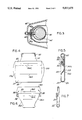
- FIG. 1 illustrates a projected view of an inflated air bag.
- FIG. 2 illustrates a plan view of the inflated air bag.
- FIG. 3 illustrates a means for attaching the air bag to a cylindrical housing.
- FIGS. 4-19 illustrate steps in the folding of an air bag.
- FIG. 20 illustrates a partially inflated air bag.
- FIG. 21 illustrates a pressure/time relationship
- FIG. 1 illustrates an air bag 20 in its inflated state.
- the air bag comprises a main panel 22 of integral construction.
- the main panel may be fabricated of a nylon having various weave densities such as 420 denier nylon 72 ⁇ 46 or 49.5 ⁇ 49.5, 840 denier nylon having a weave density of 32 ⁇ 32, or 630 denier nylon with weave density of 38 ⁇ 38, etc.
- the main panel 22 comprises a substantially rectangular front portion 24, a top portion 26, and a bottom portion 28. Since the main panel comprising the top, front and bottom portions are of integral construction, one cannot identify precisely where one portion begins and the other portion ends.
- the top portion 26 is of a generally curved, trapezoidal-like shape tapering toward a narrow neck portion 30.
- the lateral edges 32a and 32b of the top portion are generally arcuately shaped and at some dimension (such as between points 34a and 34b) the top portion achieves it maximum width shown as A.
- the bottom portion 28 is dimensionally longer than the top portion and is similarly generally trapezoidal-like in shape and tapers toward a corresponding neck portion 30 in a manner similar to the top portion 26.
- the air bag 20 is stored in a can or cavity.
- the design of the end of the air bag may differ depending upon what type of structure the air bag is to be attached.
- the ends of both the top and bottom portions 26 and 28 respectively include a flap 40a and 40b having registered openings 42.
- the significance of the flaps 40a and 40b will be discussed below.
- This end construction may differ according to the type of attachment used.
- the air bag 20 further includes limaconical (kidney) shaped side panels 44a and b (panel 44b is not visible in FIG. 1).
- the shape of the side panels 44a,b give the air bag its elongated downward shape, which is preferred for top mounted applications.
- the narrow end 46a (and b) extend toward the neck portion 30 of the bag.
- the side panels 44a and b are sewn to the main panel 22 along sew lines such as 50a and b.
- the bag 20 may optionally include a plurality of tethers which position the bag restricting the billowing of the front portion 24.
- the tethers 52a and b are formed as rectangular or trapezoidal strips of air bag-like material extending from frontal sew lines 56a and b to the flaps 40.
- the ends of the tethers 56 proximate the flaps 40 may include a set of openings similar to openings 42.
- the tethers may also be formed as narrow strips of webbing such as used for seat belts, cargo ties, etc.
- FIG. 2 illustrates a side view of the inflated air bag and illustrates the functioning of the tethers 52a and b.
- the tethers restrict the billowing of the central portion 58 of the main panel 20.
- the tethers define the trajectory of the air bag as it inflates, that is, the tethers such as the upper tether 52a aids in pulling the air bag down so as to contact the lower torso of an occupant.
- the lower tether 52b restricts the billowing of the lower portion of the front panel during deployment so as to restrict the impact of the air bag with the upper torso and head of an occupant.
- FIG. 3 illustrates the means of attaching the air bag 20 to a type of housing such as a cylindrical housing or can 60.
- the method of attachment will vary with the specific application mounting and storage scheme used.
- One such technique is taught in the commonly owned U.S. Pat. No. 401,216, "Integral Retainer and Heat Shield", which is incorporated herein by reference.
- FIG. 3 illustrates an open ended cylindrical retainer 60 having a plurality of studs 62 extending therefrom for securing a gas generator 64 therein. It is envisioned that the retainer 60 would be inserted into the open end 66 proximate the neck 30 of the air bag shown in FIG. 1 with the studs extending outwardly.
- the flaps 40a and b would be folded upon themselves such that the sets of openings are registered one to the other and then these registered openings would be fitted about the plurality of studs such as stud 62 thereby securing the air bag about the cylinder.
- the cylinder could be placed in a canister or outer housing 66.
- the ends of the tethers 52a and b may include a set of openings similar to 42 wherein the tethers are similarly wrapped about the can 60 and secured by the respective studs 62.
- the purpose of the air bag 20 is to restrain a non-driving passenger and a middle passenger, where applicable, within the vehicle.
- the air bag 20 may not be completely symmetrical about a centerline 70 (see FIG. 8).
- the right hand portion 72 of the air bag will impact and be restrained at the right hand door of the vehicle and, as such need not extend outwardly as far as the left hand side 74 of the air bag would extend toward the middle of the vehicle to protect the middle seated occupant.
- the left hand portion of the air bag as measured relative to the centerline 70 may be greater than the right hand portion.
- the bag's deflated condition it is folded relative to the retainer 60 or outer housing such as 66, proximate the neck, and stored within a portion of the vehicle such as in a portion of the dashboard.
- Typical installation locations previously used have placed the passenger side air bag 20 in a frontal facing area of the dashboard or alternatively in the vertical shelf forming the top portion of the instrument panel.
- the air bag upon inflation the air bag typically will inflate upwardly, interact with the vehicle environment and be diverted downwardly to protect the passenger.
- the bag would be laid flat with the bottom portion 28 of the air bag also laid flat and with the front portion 22 folded over the top portion of the air bag as shown in FIGS. 4 and 5.
- FIG. 4 certain of the sew lines 50a and b are visible in FIG. 4.
- the bottom and front portions 22 and 28 form a first lateral extending fold 80.
- the sew lines 56a and b for the tethers 52a and b are also visible in FIG. 4.
- the top 26 and front portions 22 form a second laterally extending fold 82. Thereafter, the top portion 26 is flattened by taking the second lateral fold 82 and moving it forwardly in the direction of arrow 84 (see FIG. 5) to the configuration of FIGS. 6 and 7. As can be seen from FIGS. 6 and 7, this operation forms a rear facing lateral fold 84.
- portions of the air bag 20 including its side panels 44a and b, proximate the sides of the air bag have been pushed, placed or folded inwardly so as to form the arcuately shaped edges 86a and b of air bag material.
- first and second fore-aft exterior folds 90 and 92 are brought forwardly and inwardly, as indicated by arrows 88, to form first and second fore-aft exterior folds 90 and 92 on each side of the bag 20 and a first interior fold 94.
- first and second fore-aft folds on both sides of the bag 20 at least towards the rear of the bag are aligned generally along edges 86a,b.
- the first interior fold 94 will extend generally along the lines of the previously folded bag material (see reference numerals 44a and b).
- FIG. 9 which is a cross sectional view through a portion of the folded bag of FIG. 8 showing a portion of the first and second fore-aft exterior folds 90 and 92 in generally overlapping condition and the first interior fold 94 facing the centerline 70 of the bag. It should be appreciated that these folds may not be symmetrically positioned if the bag is itself unsymmetric about the centerline 70.
- the center point of the first interior fold (or at least the outer of the two layers of material forming the fold 94) is moved outwardly generally shown by arrows 97 of FIG. 8 and moved such that the material lying along the first interior fold 94 is brought outwardly toward the edges 86a and b of the bag and aligned in a registered condition with the first and second fore-aft folds 90 and 92 respectively, thereby yielding, at least along a portion of the edges 86a and b, a third fore-aft fold shown as 94'.
- this folded condition there will also exist two fore-aft inner folds 96 and 96'.
- the lateral width of the forward positions, i.e., edges, of the bag is approximately the lateral dimension of the neck portion 30.
- the cavity, can or housing such as 66 used to house the folded bag is approximately slightly larger than the width of the neck. This is accomplished by defining on the top and bottom portions 26 and 28 of the partially folded air bag respective sets of top and bottom fold lines 100a and b, the lateral spacing being generally approximately equal to the width dimension of the neck portion 30.
- the top fold line 100a may be seen in FIGS. 10 and 11, while the bottom fold line is diagrammatically shown in FIG. 11.
- first, second and third exterior folds 90, 92 and 94' are moved inwardly toward the bag centerline 70 such that the outward edges of the folds become registered with the fold lines 100a and b, thereby forming respective top and bottom folds 102 and 104 in each side of the bag. Again because of the unusual shape of the air bag 20, the inward penetration of each of these top and bottom folds will vary.
- the planar dimension of the bag is essentially rectangular in shape (although slightly irregular) emanating from the neck portion 30 as shown in FIG. 12 having a width of about 90% of the opening of the exterior housing into which the bag is to be placed.
- the end of the bag opposite the neck 30 is rolled or folded relatively tightly toward the neck 30, and retainer 60 if used.
- This rolling or folding may either be in a clockwise fashion wherein the bottom portion 28 of the air bag is rolled essentially over the top portion yielding a counter-clockwise spiral roll as shown in FIG. 14, or alternatively, the bag of FIG. 12 may be rolled in a counter-clockwise manner with the bottom portion of the bag rolled beneath the top portion of the bag yielding a clockwise spiral roll as shown in FIG. 15.
- the rolling of the bag is terminated at a point approximately 2.25 to 2.5 times the exterior housing opening width of the length of the unrolled bag, such point being shown as point 110 in FIGS. 14 and 15.
- the rolled portion 112 of the air bag is moved laterally adjacent the retainer 60 or other means used to secure the neck 30 to form an upwardly extending flap 114.
- the flap 114 is thereafter moved in a generally counter-clockwise position to envelope the previously rolled portion 112 of the air bag thereby completing the folding thereof.
- the air bag in its folded configuration may be secured to the can by enveloping the air bag and retainer with a rupturable or frangible wrapping such as a spun bonded polyolefin material 118.
- a rupturable or frangible wrapping such as a spun bonded polyolefin material 118.
- One such material is manufactured by E. I. DuPont under the trade name of TYVEK.
- the material may include a line of perforations to define a tear line.
- the gas generator 64 is placed in the retainer 60 and the assembly placed in the exterior housing 66.
- the air bag is inserted in the external housing 66 with the gas generator 64 being installed through a
- FIG. 1 there is shown a dotted circle 120 in the side panel 44a of the air bag 20.
- the general area defined by the dotted line 120 will be positioned proximate an open end of the can 60. If the material approximate the circle 120 is removed or alternatively slit, thereby yielding access to one of the open ends of the can 60, a gas generator such as 64 may be inserted therein and secured to the can thereby completing the air bag module comprising the can 60, the air bag 20, and the gas generator 64.
- the operation of the invention during inflation of the air bag 20 is as follows. Inflating gas supplied by an inflation medium such as the gas generator, compressed gas source, or combination of the two or otherwise, is activated during a crash situation thereby initiating deployment of the air bag. The inflation gas is communicated through the neck portion of the air bag and momentarily into the internal portions of the flap 114. Almost immediately the flap 114 is inflated to the position shown in FIG. 20 forming a top bubble 116 which momentarily acts as a restraining means on the remaining folded and rolled portions of the air bag 20. The formation of this bubble 116 is a transitory phenomenon and disappears upon complete inflation of the air bag 20.
- an inflation medium such as the gas generator, compressed gas source, or combination of the two or otherwise
- the exterior wrapped material 118 positioned about the folded air bag tears to permit the bag to expand outwardly.
- the now inflated flap 114 or bubble 116 forms a momentary relatively rigid top wall of the partially inflated air bag. With this relatively rigid wall in place further introduction of inflation gas into the air bag causes the rolled portion and folded portion of the bag 20 to expand. Also as a momentary phenomenon, as the bag unrolls it exposes portions of the side folds 90, 94; 92, 102, 104 of the bag to the inflation gas thereby enhancing the lateral or sideways deployment of the bag. Further unrolling of the roll will expose additional portions of the side folds to the inflation gas. This process continues as the bag unrolls completely and the side folds expand.
- the expansion of the air bag can be seen as a series of sequential though continuous steps wherein as the air bag unrolls parts of the folds are exposed to the inflation gas and as such, at any instant the portion of the bag that has previously been unrolled and unfolded is fully expanded thereby maintaining a continuous positive pressure within the bag.
- FIG. 21 illustrates the typical air bag pressure graphs shown in FIG. 21 which illustrates the internal bag pressure as a function of time for the present invention and for the same air bag folded in a bellows or accordion-like manner. This graph is representative of air bag performance and has been verified by testing.
- This type of fold has been referred to in the prior art as an accordion fold. One may envision this accordion fold with reference to FIG.
- the air bag pressure attains a momentary maximum value of approximately 25 psi, for most current housing geometries, in approximately 10 milliseconds after inflation, and full deployment is achieved at approximately the 50 milliseconds.
- the secondary peak air bag pressure is developed at 55 milliseconds and is maintained for 40-50 milliseconds, i.e. throughout the occupant interaction with the air bag.
- the distinct difference between the operation of the present invention and the accordion folded air bag is in the 10 to 25-30 millisecond time frame wherein it can be seen that the accordion folded air bag is negatively pressurized.
- HIC Head Injury Criterion
- the accordion fold identical bag
- HIC is a crash worthiness criterion defined in FMVSS 208.
- the bag slap a measurement of the impact of the air bag on the occupant, was 859 G's and 376 G's for the accordion and the present invention respectively (a 230% improvement).
Landscapes
- Engineering & Computer Science (AREA)
- Mechanical Engineering (AREA)
- Air Bags (AREA)
Abstract
Description
Claims (16)
Priority Applications (1)
| Application Number | Priority Date | Filing Date | Title |
|---|---|---|---|
| US07/444,068 US5022675A (en) | 1989-11-30 | 1989-11-30 | Air bag and folding technique |
Applications Claiming Priority (1)
| Application Number | Priority Date | Filing Date | Title |
|---|---|---|---|
| US07/444,068 US5022675A (en) | 1989-11-30 | 1989-11-30 | Air bag and folding technique |
Publications (1)
| Publication Number | Publication Date |
|---|---|
| US5022675A true US5022675A (en) | 1991-06-11 |
Family
ID=23763361
Family Applications (1)
| Application Number | Title | Priority Date | Filing Date |
|---|---|---|---|
| US07/444,068 Expired - Fee Related US5022675A (en) | 1989-11-30 | 1989-11-30 | Air bag and folding technique |
Country Status (1)
| Country | Link |
|---|---|
| US (1) | US5022675A (en) |
Cited By (106)
| Publication number | Priority date | Publication date | Assignee | Title |
|---|---|---|---|---|
| US5129675A (en) * | 1991-05-02 | 1992-07-14 | General Motors Corporation | Occupant restraint cushion |
| US5140799A (en) * | 1990-08-20 | 1992-08-25 | Takata Corporation | Method of folding away air bag for passenger seat |
| US5162035A (en) * | 1991-11-07 | 1992-11-10 | Jamal Saklou | Bag folding system |
| US5178407A (en) * | 1991-07-08 | 1993-01-12 | Trw Vehicle Safety System Inc. | Folded air bag |
| WO1993001955A1 (en) * | 1991-07-25 | 1993-02-04 | Allied-Signal Inc. | A method of manufacturing an air bag |
| EP0553542A1 (en) * | 1992-01-28 | 1993-08-04 | General Engineering (Netherlands) B.V. | Improvements in or relating to an air-bag arrangement |
| US5240282A (en) * | 1992-05-22 | 1993-08-31 | Allied Signal Inc. | Air bag and folding technique |
| US5275435A (en) * | 1992-08-04 | 1994-01-04 | Trw Vehicle Safety Systems Inc. | Folded air bag |
| US5290061A (en) * | 1992-10-14 | 1994-03-01 | Trw Vehicle Safety Systems Inc. | Folded air bag |
| EP0586131A1 (en) * | 1992-09-01 | 1994-03-09 | Morton International, Inc. | Tethers with tearseams for air bag cushion |
| US5300011A (en) * | 1992-10-14 | 1994-04-05 | The Omega Company, Inc. | Automatic airbag folding apparatus and method |
| EP0593172A1 (en) * | 1992-10-16 | 1994-04-20 | Morton International, Inc. | Multi-chamber passenger air bag cushion with interchamber venting |
| US5306043A (en) * | 1991-10-24 | 1994-04-26 | Trw Vehicle Safety Systems Inc. | Dashboard top mounted vehicle air bag assembly |
| US5310216A (en) * | 1992-10-30 | 1994-05-10 | Alliedsignal Inc. | Flat sew pattern passenger air bag |
| US5310214A (en) * | 1992-04-02 | 1994-05-10 | Talley Automotive Products, Inc. | Air bag system for restraining movement of an adult and/or a child |
| US5316337A (en) * | 1992-03-30 | 1994-05-31 | Toyo Tire & Rubber Co., Ltd. | Inflatable bags for airbag passive restraint systems for front seat passenger and methods for manufacturing thereof |
| US5342087A (en) * | 1990-11-27 | 1994-08-30 | Mazda Motor Corporation | Air bag for vehicle safety device |
| EP0614785A1 (en) * | 1993-03-11 | 1994-09-14 | Morton International, Inc. | Passenger side air bag with controlled deployment |
| US5348341A (en) * | 1993-11-01 | 1994-09-20 | General Motors Corporation | Method of folding an air bag |
| US5358273A (en) * | 1992-03-09 | 1994-10-25 | Toyo Tire & Rubber Co., Ltd. | Inflatable bags for airbag passive restraint systems for driver and method for production thereof |
| JPH06305388A (en) * | 1993-04-02 | 1994-11-01 | Morton Internatl Inc | Vehicle occupant restraint system |
| US5364123A (en) * | 1994-01-31 | 1994-11-15 | General Motors Corporation | Air bag module |
| US5382048A (en) * | 1993-11-05 | 1995-01-17 | Morton International, Inc. | Soft deployment air bag fold |
| US5391137A (en) * | 1993-10-29 | 1995-02-21 | The Omega Company Inc. | Airbag folding apparatus and method |
| US5398958A (en) * | 1994-04-15 | 1995-03-21 | Trw Vehicle Safety Systems Inc. | Tethered attachment for an air bag |
| US5425551A (en) * | 1993-12-17 | 1995-06-20 | General Motors Corporation | Cushion fold for a supplemental inflatable restraint system |
| US5456651A (en) * | 1993-11-08 | 1995-10-10 | Automated Solutions, Inc. | Automatic bag folding apparatus |
| GB2290061A (en) * | 1994-06-10 | 1995-12-13 | Takata Corp | Air bag with flaps round inflator opening |
| US5478113A (en) * | 1994-11-18 | 1995-12-26 | Morton International, Inc. | Airbag and inverted folding method |
| US5496056A (en) * | 1995-02-21 | 1996-03-05 | Morton International, Inc. | Automotive passenger air bag module cushion fold |
| US5498030A (en) * | 1995-03-28 | 1996-03-12 | General Motors Corporation | Air bag module |
| US5501489A (en) * | 1995-03-30 | 1996-03-26 | Morton International, Inc. | Fully extended pleat for passenger air bag fold |
| US5503429A (en) * | 1994-09-01 | 1996-04-02 | Trw Vehicle Safety Systems Inc. | Vehicle occupant restraint apparatus and method of assembly |
| EP0709260A1 (en) * | 1994-10-18 | 1996-05-01 | Morton International, Inc. | Inflatable cushion assembly |
| US5513877A (en) * | 1994-12-02 | 1996-05-07 | General Motors Corporation | Vehicle body/supplemental inflation restraint arrangement |
| EP0712761A1 (en) * | 1994-11-15 | 1996-05-22 | TRW Occupant Restraint Systems GmbH | Folding method of an air bag for a vehicle occupant restraint system, device for performing this method and air bag so obtained |
| US5520413A (en) * | 1995-09-11 | 1996-05-28 | Morton International, Inc. | Partitioned multi-cell air bag |
| USRE35265E (en) * | 1991-11-07 | 1996-06-04 | Baker; William F. | Bag folding system |
| US5527062A (en) * | 1991-04-20 | 1996-06-18 | Kolbenschmidt Aktiengesellschaft | Air bag apparatus for impact protection |
| US5529339A (en) * | 1995-03-20 | 1996-06-25 | General Motors Corporation | Air bag fold and method |
| US5531477A (en) * | 1995-06-06 | 1996-07-02 | Alliedsignal Inc. | Method of folding an airbag |
| US5538281A (en) * | 1995-03-31 | 1996-07-23 | Trw Vehicle Safety Systems Inc. | Folded air bag |
| US5568938A (en) * | 1992-10-09 | 1996-10-29 | General Engineering (Netherlands) Bv | Air-bag arrangement |
| US5575748A (en) * | 1994-03-10 | 1996-11-19 | The Omega Company, Inc. | Airbag folding engine adaptable for folding a plurality of airbag designs |
| US5605350A (en) * | 1995-05-30 | 1997-02-25 | General Motors Corporation | Air bag fold and method |
| US5613348A (en) * | 1995-03-31 | 1997-03-25 | Morton International, Inc. | Method and apparatus for packing an inflatable air bag in a housing of an air bag module assembly |
| US5632506A (en) * | 1996-06-14 | 1997-05-27 | Trw Vehicle Safety Systems Inc. | Vehicle occupant protection apparatus |
| US5636861A (en) * | 1996-01-29 | 1997-06-10 | Trw Vehicle Safety Systems Inc. | Air bag module |
| US5636860A (en) * | 1995-11-28 | 1997-06-10 | Trw Vehicle Safety Systems Inc. | Air bag and folding method |
| US5664805A (en) * | 1993-11-05 | 1997-09-09 | Takata Corporation | Air bag |
| US5667241A (en) * | 1995-10-17 | 1997-09-16 | Morton International, Inc. | Seat mounted side impact airbags |
| US5683109A (en) * | 1995-10-31 | 1997-11-04 | Alliedsignal Inc. | Two piece air bag with built in tether |
| US5755078A (en) * | 1996-12-04 | 1998-05-26 | Omega Automation, Inc. | Method and apparatus for folding an inflatable cushion |
| US5765863A (en) * | 1996-03-27 | 1998-06-16 | Morton International, Inc. | Airbag cushion having compression-deployed section |
| US5785349A (en) * | 1996-12-03 | 1998-07-28 | Morton International, Inc. | Elongated asymmetrical automotive airbag |
| US5795284A (en) * | 1994-11-15 | 1998-08-18 | Trw Occupant Restraint Systems Gmbh | Method of and device for folding a gas bag of a vehicle occupant restraint system |
| WO1998036947A1 (en) * | 1997-02-20 | 1998-08-27 | Autoliv Development Ab | Airbag module with a receiving pocket for a gas sack with gas generator |
| US5800328A (en) * | 1994-11-15 | 1998-09-01 | Trw Occupant Restraint Systems Gmbh | Method of and device for folding a gas bag of a vehicle occupant restraint system |
| US5803483A (en) * | 1997-03-20 | 1998-09-08 | Autoliv Asp, Inc. | Airbag cushion and method of folding thereof |
| US5810385A (en) * | 1992-06-23 | 1998-09-22 | Mercedes-Benz Ag | Collision-protection system having an airbag |
| US5823567A (en) * | 1996-07-03 | 1998-10-20 | Precision Fabrics Group, Inc. | Folded inflatable protective device and method for making same |
| US5865467A (en) * | 1996-04-01 | 1999-02-02 | Toyo Tire & Rubber Co., Ltd. | Airbag for front seat passenger |
| US5868660A (en) * | 1994-12-20 | 1999-02-09 | Toyoda Gosei Co., Ltd. | Method and apparatus for folding up air bag |
| US5984852A (en) * | 1996-08-19 | 1999-11-16 | Takata (Europe) Vehicle Safety Technology Gmbh | Method for accommodating an airbag of an airbag apparatus in a container |
| US5997036A (en) * | 1996-12-09 | 1999-12-07 | Ikeda Bussan Co., Ltd. | Air bag device and method of producing same |
| US6364341B1 (en) * | 1999-11-30 | 2002-04-02 | Breed Automotive Technology, Inc. | Air bag and module |
| US6386584B1 (en) * | 2000-05-25 | 2002-05-14 | General Motors Corporation | Air bag fold indicator |
| JP3339099B2 (en) | 1993-04-12 | 2002-10-28 | タカタ株式会社 | Airbag device for passenger seat |
| US6536800B2 (en) * | 2000-02-25 | 2003-03-25 | Takata Corporation | Airbag device |
| US6616177B2 (en) * | 2001-06-11 | 2003-09-09 | General Motors Corporation | Dual depth airbag |
| US20040012182A1 (en) * | 2002-07-22 | 2004-01-22 | Ramesh Keshavaraj | Profile tuner panel for inflatable cushions |
| EP1388466A1 (en) * | 2002-08-09 | 2004-02-11 | TAKATA-PETRI (Ulm) GmbH | Passanger safety device for vehicles |
| US20040051281A1 (en) * | 2002-06-27 | 2004-03-18 | Takata Corporation | Airbag apparatus, motorcycle with airbag apparatus, and method of manufacturing airbag apparatus |
| US20040251669A1 (en) * | 2001-03-30 | 2004-12-16 | Trw Vehicle Safety Systems Inc. | Method of folding air bag and an associated apparatus |
| US20040256842A1 (en) * | 1994-05-23 | 2004-12-23 | Breed David S. | Knee bolster airbag system |
| KR20050017520A (en) * | 2003-08-14 | 2005-02-22 | 현대모비스 주식회사 | Air-Bag System |
| US20050070414A1 (en) * | 2003-09-11 | 2005-03-31 | Schneider David W. | Cushion fold patterns for overhead airbags |
| US20050110244A1 (en) * | 2003-11-20 | 2005-05-26 | Wheelwright Terry A. | High internal pressure fabric airbag with exposed inflator |
| US20060131858A1 (en) * | 2004-12-22 | 2006-06-22 | Ford Global Technologies, Llc | An air bag and a method of folding an air bag |
| US20070018437A1 (en) * | 2005-07-25 | 2007-01-25 | Masahiro Hasebe | Airbag Device |
| EP1747948A1 (en) * | 2005-07-25 | 2007-01-31 | Takata Corporation | Airbag device comprising folded airbag wrapped by a sheet |
| US20070075530A1 (en) * | 2005-09-30 | 2007-04-05 | Nihon Plast Co., Ltd. | Vehicular air bag, air bag module having the vehicular air bag and method of folding the air bag |
| US20070267851A1 (en) * | 2003-06-20 | 2007-11-22 | Ernma Svenbrant | Air Bag |
| US20080061536A1 (en) * | 2006-09-13 | 2008-03-13 | Masahiro Hasebe | Airbag device |
| WO2008124497A1 (en) * | 2007-04-03 | 2008-10-16 | Delphi Technologies, Inc. | Apparatus and method for controlling an inflatable cushion |
| US20090102173A1 (en) * | 2005-04-27 | 2009-04-23 | Autoliv Asp, Inc. | Airbag cushion folding methods |
| US20090108574A1 (en) * | 2005-04-27 | 2009-04-30 | Autoliv Asp, Inc. | Airbag cushion folding methods |
| US20090160171A1 (en) * | 2007-12-21 | 2009-06-25 | Cis Tech, Llc | Low risk deployment driver airbag system |
| US20090256340A1 (en) * | 2008-04-10 | 2009-10-15 | Autoliv Asp, Inc. | Airbag assembly and method of packing |
| US20110088356A1 (en) * | 2009-10-16 | 2011-04-21 | Autoliv Asp, Inc. | Inflatable airbag cushions with deployment flaps and methods for folding |
| US8226118B2 (en) | 2009-08-05 | 2012-07-24 | Autoliv Asp, Inc. | Safety venting with passively closeable vents |
| US8540276B2 (en) | 2011-11-07 | 2013-09-24 | Autoliv Asp, Inc. | Inflatable knee airbag assemblies with cushion fold pattern |
| US20150074969A1 (en) * | 2013-09-17 | 2015-03-19 | Ford Global Technologies, Llc | Integrated passenger airbag |
| US9004216B1 (en) | 2013-11-18 | 2015-04-14 | Ford Global Technologies, Llc | Front rail mounted airbag |
| US20150151707A1 (en) * | 2013-12-03 | 2015-06-04 | Ford Global Technologies, Llc | Head, torso and knee combo airbag |
| US9127968B2 (en) | 2013-11-18 | 2015-09-08 | Ford Global Technologies, Llc | Flexible optical impact detection sensor for front rail mounted airbag |
| US9139153B2 (en) | 2013-09-05 | 2015-09-22 | Ford Global Technologies, Llc | Vehicle side impact airbag with laterally extending thoracic chamber |
| US9162645B2 (en) | 2013-12-20 | 2015-10-20 | Ford Global Technologies, Llc | High pressure airbag for oblique impact modes |
| US9561774B2 (en) | 2014-04-24 | 2017-02-07 | Ford Global Technologies, Llc | Winged driver airbag |
| JP2017030631A (en) * | 2015-08-04 | 2017-02-09 | タカタ株式会社 | Air back device and vehicle structure |
| US9566937B1 (en) * | 2013-08-29 | 2017-02-14 | Tk Holdings Inc. | Passenger airbag |
| US9713998B2 (en) * | 2014-04-24 | 2017-07-25 | Ford Global Technologies, Llc | Corrugated passenger airbag |
| US9969349B2 (en) | 2014-04-24 | 2018-05-15 | Ford Global Technologies, Llc | Passenger airbag with extended base |
| US20180297550A1 (en) * | 2017-04-14 | 2018-10-18 | Toyota Jidosha Kabushiki Kaisha | Airbag device for front passenger seat and airbag folding method |
| US11299122B2 (en) * | 2020-06-15 | 2022-04-12 | Hyundai Motor Company | Airbag apparatus |
| US20230058627A1 (en) * | 2020-03-31 | 2023-02-23 | Honda Motor Co., Ltd. | Saddle-ride type vehicle |
Citations (8)
| Publication number | Priority date | Publication date | Assignee | Title |
|---|---|---|---|---|
| US3596443A (en) * | 1969-10-29 | 1971-08-03 | Modern Dust Bag Co Inc | Vacuum cleaner filter bag |
| US3748477A (en) * | 1971-09-22 | 1973-07-24 | Allied Chem | Cushion fold |
| US4004828A (en) * | 1974-08-19 | 1977-01-25 | Nissan Motor Co., Ltd. | Vehicle safety device using an inflatable confinement and method of folding the inflatable confinement |
| JPS53147341A (en) * | 1977-05-25 | 1978-12-22 | Nissan Motor Co Ltd | Method of folding air cushion |
| US4235453A (en) * | 1974-05-13 | 1980-11-25 | Allied Chemical Corporation | Specially folded vehicle safety bag |
| US4286954A (en) * | 1979-12-03 | 1981-09-01 | General Motors Corporation | Method of folding an inflatable restraint cushion |
| US4351544A (en) * | 1974-03-27 | 1982-09-28 | Tsuneyo Ross | Inflatable apparatus and methods of constructing and utilizing same |
| US4512464A (en) * | 1984-08-03 | 1985-04-23 | Amscomatic, Inc. | Method of folding T-shirts and folded shirt arrangement resulting therefrom |
-
1989
- 1989-11-30 US US07/444,068 patent/US5022675A/en not_active Expired - Fee Related
Patent Citations (8)
| Publication number | Priority date | Publication date | Assignee | Title |
|---|---|---|---|---|
| US3596443A (en) * | 1969-10-29 | 1971-08-03 | Modern Dust Bag Co Inc | Vacuum cleaner filter bag |
| US3748477A (en) * | 1971-09-22 | 1973-07-24 | Allied Chem | Cushion fold |
| US4351544A (en) * | 1974-03-27 | 1982-09-28 | Tsuneyo Ross | Inflatable apparatus and methods of constructing and utilizing same |
| US4235453A (en) * | 1974-05-13 | 1980-11-25 | Allied Chemical Corporation | Specially folded vehicle safety bag |
| US4004828A (en) * | 1974-08-19 | 1977-01-25 | Nissan Motor Co., Ltd. | Vehicle safety device using an inflatable confinement and method of folding the inflatable confinement |
| JPS53147341A (en) * | 1977-05-25 | 1978-12-22 | Nissan Motor Co Ltd | Method of folding air cushion |
| US4286954A (en) * | 1979-12-03 | 1981-09-01 | General Motors Corporation | Method of folding an inflatable restraint cushion |
| US4512464A (en) * | 1984-08-03 | 1985-04-23 | Amscomatic, Inc. | Method of folding T-shirts and folded shirt arrangement resulting therefrom |
Cited By (149)
| Publication number | Priority date | Publication date | Assignee | Title |
|---|---|---|---|---|
| US5140799A (en) * | 1990-08-20 | 1992-08-25 | Takata Corporation | Method of folding away air bag for passenger seat |
| US5342087A (en) * | 1990-11-27 | 1994-08-30 | Mazda Motor Corporation | Air bag for vehicle safety device |
| US5527062A (en) * | 1991-04-20 | 1996-06-18 | Kolbenschmidt Aktiengesellschaft | Air bag apparatus for impact protection |
| US5129675A (en) * | 1991-05-02 | 1992-07-14 | General Motors Corporation | Occupant restraint cushion |
| US5178407A (en) * | 1991-07-08 | 1993-01-12 | Trw Vehicle Safety System Inc. | Folded air bag |
| WO1993001955A1 (en) * | 1991-07-25 | 1993-02-04 | Allied-Signal Inc. | A method of manufacturing an air bag |
| US5222932A (en) * | 1991-07-25 | 1993-06-29 | Allied-Signal Inc. | Air bag and method of manufacture |
| US5306043A (en) * | 1991-10-24 | 1994-04-26 | Trw Vehicle Safety Systems Inc. | Dashboard top mounted vehicle air bag assembly |
| US5162035A (en) * | 1991-11-07 | 1992-11-10 | Jamal Saklou | Bag folding system |
| USRE35265E (en) * | 1991-11-07 | 1996-06-04 | Baker; William F. | Bag folding system |
| EP0553542A1 (en) * | 1992-01-28 | 1993-08-04 | General Engineering (Netherlands) B.V. | Improvements in or relating to an air-bag arrangement |
| US5358273A (en) * | 1992-03-09 | 1994-10-25 | Toyo Tire & Rubber Co., Ltd. | Inflatable bags for airbag passive restraint systems for driver and method for production thereof |
| US5316337A (en) * | 1992-03-30 | 1994-05-31 | Toyo Tire & Rubber Co., Ltd. | Inflatable bags for airbag passive restraint systems for front seat passenger and methods for manufacturing thereof |
| US5310214A (en) * | 1992-04-02 | 1994-05-10 | Talley Automotive Products, Inc. | Air bag system for restraining movement of an adult and/or a child |
| US5240282A (en) * | 1992-05-22 | 1993-08-31 | Allied Signal Inc. | Air bag and folding technique |
| US5810385A (en) * | 1992-06-23 | 1998-09-22 | Mercedes-Benz Ag | Collision-protection system having an airbag |
| US5275435A (en) * | 1992-08-04 | 1994-01-04 | Trw Vehicle Safety Systems Inc. | Folded air bag |
| EP0586131A1 (en) * | 1992-09-01 | 1994-03-09 | Morton International, Inc. | Tethers with tearseams for air bag cushion |
| US5489119A (en) * | 1992-09-01 | 1996-02-06 | Morton International, Inc. | Tethers with tearseams for air bag cushion |
| US5568938A (en) * | 1992-10-09 | 1996-10-29 | General Engineering (Netherlands) Bv | Air-bag arrangement |
| US5300011A (en) * | 1992-10-14 | 1994-04-05 | The Omega Company, Inc. | Automatic airbag folding apparatus and method |
| US5290061A (en) * | 1992-10-14 | 1994-03-01 | Trw Vehicle Safety Systems Inc. | Folded air bag |
| EP0593172A1 (en) * | 1992-10-16 | 1994-04-20 | Morton International, Inc. | Multi-chamber passenger air bag cushion with interchamber venting |
| US5310216A (en) * | 1992-10-30 | 1994-05-10 | Alliedsignal Inc. | Flat sew pattern passenger air bag |
| EP0614785A1 (en) * | 1993-03-11 | 1994-09-14 | Morton International, Inc. | Passenger side air bag with controlled deployment |
| US5395134A (en) * | 1993-04-02 | 1995-03-07 | Morton International, Inc. | Passenger side air bag with controlled deployment |
| JPH06305388A (en) * | 1993-04-02 | 1994-11-01 | Morton Internatl Inc | Vehicle occupant restraint system |
| JP3339099B2 (en) | 1993-04-12 | 2002-10-28 | タカタ株式会社 | Airbag device for passenger seat |
| US5391137A (en) * | 1993-10-29 | 1995-02-21 | The Omega Company Inc. | Airbag folding apparatus and method |
| US5348341A (en) * | 1993-11-01 | 1994-09-20 | General Motors Corporation | Method of folding an air bag |
| EP0652139A1 (en) * | 1993-11-05 | 1995-05-10 | Morton International, Inc. | Soft deployment air bag fold |
| JP2667367B2 (en) | 1993-11-05 | 1997-10-27 | モートン インターナショナル,インコーポレイティド | Folded airbag cushion and how to fold it |
| US5382048A (en) * | 1993-11-05 | 1995-01-17 | Morton International, Inc. | Soft deployment air bag fold |
| JPH07215151A (en) * | 1993-11-05 | 1995-08-15 | Morton Internatl Inc | Inflatable folding air bag cushion and folding method thereof |
| US5664805A (en) * | 1993-11-05 | 1997-09-09 | Takata Corporation | Air bag |
| US5456651A (en) * | 1993-11-08 | 1995-10-10 | Automated Solutions, Inc. | Automatic bag folding apparatus |
| US5425551A (en) * | 1993-12-17 | 1995-06-20 | General Motors Corporation | Cushion fold for a supplemental inflatable restraint system |
| US5364123A (en) * | 1994-01-31 | 1994-11-15 | General Motors Corporation | Air bag module |
| US5772570A (en) * | 1994-03-10 | 1998-06-30 | Omega Automation, Inc. | Airbag folding engine adaptable for folding a plurality of airbag designs |
| US5575748A (en) * | 1994-03-10 | 1996-11-19 | The Omega Company, Inc. | Airbag folding engine adaptable for folding a plurality of airbag designs |
| US5398958A (en) * | 1994-04-15 | 1995-03-21 | Trw Vehicle Safety Systems Inc. | Tethered attachment for an air bag |
| US20040256842A1 (en) * | 1994-05-23 | 2004-12-23 | Breed David S. | Knee bolster airbag system |
| GB2290061B (en) * | 1994-06-10 | 1998-04-15 | Takata Corp | Air bag |
| GB2290061A (en) * | 1994-06-10 | 1995-12-13 | Takata Corp | Air bag with flaps round inflator opening |
| US5503429A (en) * | 1994-09-01 | 1996-04-02 | Trw Vehicle Safety Systems Inc. | Vehicle occupant restraint apparatus and method of assembly |
| EP0709260A1 (en) * | 1994-10-18 | 1996-05-01 | Morton International, Inc. | Inflatable cushion assembly |
| US5542692A (en) * | 1994-10-18 | 1996-08-06 | Morton International, Inc. | Inflatable cushion assembly and system |
| US5800328A (en) * | 1994-11-15 | 1998-09-01 | Trw Occupant Restraint Systems Gmbh | Method of and device for folding a gas bag of a vehicle occupant restraint system |
| EP0712761A1 (en) * | 1994-11-15 | 1996-05-22 | TRW Occupant Restraint Systems GmbH | Folding method of an air bag for a vehicle occupant restraint system, device for performing this method and air bag so obtained |
| US5795284A (en) * | 1994-11-15 | 1998-08-18 | Trw Occupant Restraint Systems Gmbh | Method of and device for folding a gas bag of a vehicle occupant restraint system |
| US5613707A (en) * | 1994-11-15 | 1997-03-25 | Trw Occupant Restraint Systems Gmbh | Method of arranging a gas bag in a compartment |
| US5478113A (en) * | 1994-11-18 | 1995-12-26 | Morton International, Inc. | Airbag and inverted folding method |
| EP0712763A1 (en) | 1994-11-18 | 1996-05-22 | Morton International, Inc. | Airbag and inverted folding method therefor |
| US5513877A (en) * | 1994-12-02 | 1996-05-07 | General Motors Corporation | Vehicle body/supplemental inflation restraint arrangement |
| US5868660A (en) * | 1994-12-20 | 1999-02-09 | Toyoda Gosei Co., Ltd. | Method and apparatus for folding up air bag |
| US5496056A (en) * | 1995-02-21 | 1996-03-05 | Morton International, Inc. | Automotive passenger air bag module cushion fold |
| US5529339A (en) * | 1995-03-20 | 1996-06-25 | General Motors Corporation | Air bag fold and method |
| US5498030A (en) * | 1995-03-28 | 1996-03-12 | General Motors Corporation | Air bag module |
| US5501489A (en) * | 1995-03-30 | 1996-03-26 | Morton International, Inc. | Fully extended pleat for passenger air bag fold |
| EP0734913A3 (en) * | 1995-03-30 | 1996-12-18 | Morton Int Inc | Folded air bag and method of folding an air bag |
| EP0734913A2 (en) * | 1995-03-30 | 1996-10-02 | Morton International, Inc. | Folded air bag and method of folding an air bag |
| US5538281A (en) * | 1995-03-31 | 1996-07-23 | Trw Vehicle Safety Systems Inc. | Folded air bag |
| US5613348A (en) * | 1995-03-31 | 1997-03-25 | Morton International, Inc. | Method and apparatus for packing an inflatable air bag in a housing of an air bag module assembly |
| US5694737A (en) * | 1995-03-31 | 1997-12-09 | Morton International, Inc. | Method and apparatus for packing an inflatable air bag in a housing of an air bag module assembly |
| US5605350A (en) * | 1995-05-30 | 1997-02-25 | General Motors Corporation | Air bag fold and method |
| US5531477A (en) * | 1995-06-06 | 1996-07-02 | Alliedsignal Inc. | Method of folding an airbag |
| EP0788933A3 (en) * | 1995-09-11 | 1999-02-10 | Morton International, Inc. | Partitioned multi-cell air bag |
| US5520413A (en) * | 1995-09-11 | 1996-05-28 | Morton International, Inc. | Partitioned multi-cell air bag |
| EP0788933A2 (en) * | 1995-09-11 | 1997-08-13 | Morton International, Inc. | Partitioned multi-cell air bag |
| US5667241A (en) * | 1995-10-17 | 1997-09-16 | Morton International, Inc. | Seat mounted side impact airbags |
| US5683109A (en) * | 1995-10-31 | 1997-11-04 | Alliedsignal Inc. | Two piece air bag with built in tether |
| US5636860A (en) * | 1995-11-28 | 1997-06-10 | Trw Vehicle Safety Systems Inc. | Air bag and folding method |
| US5636861A (en) * | 1996-01-29 | 1997-06-10 | Trw Vehicle Safety Systems Inc. | Air bag module |
| US5765863A (en) * | 1996-03-27 | 1998-06-16 | Morton International, Inc. | Airbag cushion having compression-deployed section |
| US5865467A (en) * | 1996-04-01 | 1999-02-02 | Toyo Tire & Rubber Co., Ltd. | Airbag for front seat passenger |
| GB2316372B (en) * | 1996-04-01 | 2000-08-02 | Toyo Tire & Rubber Co | Airbag for front seat passenger |
| US5632506A (en) * | 1996-06-14 | 1997-05-27 | Trw Vehicle Safety Systems Inc. | Vehicle occupant protection apparatus |
| EP0812736A1 (en) * | 1996-06-14 | 1997-12-17 | Trw Vehicle Safety Systems Inc. | Vehicle occupant protection apparatus |
| US5823567A (en) * | 1996-07-03 | 1998-10-20 | Precision Fabrics Group, Inc. | Folded inflatable protective device and method for making same |
| US5984852A (en) * | 1996-08-19 | 1999-11-16 | Takata (Europe) Vehicle Safety Technology Gmbh | Method for accommodating an airbag of an airbag apparatus in a container |
| US5785349A (en) * | 1996-12-03 | 1998-07-28 | Morton International, Inc. | Elongated asymmetrical automotive airbag |
| US5755078A (en) * | 1996-12-04 | 1998-05-26 | Omega Automation, Inc. | Method and apparatus for folding an inflatable cushion |
| US5997036A (en) * | 1996-12-09 | 1999-12-07 | Ikeda Bussan Co., Ltd. | Air bag device and method of producing same |
| WO1998036947A1 (en) * | 1997-02-20 | 1998-08-27 | Autoliv Development Ab | Airbag module with a receiving pocket for a gas sack with gas generator |
| US6447003B1 (en) | 1997-02-20 | 2002-09-10 | Autoliv Development Ab | Airbag module having an airbag with a receiving pocket for the gas generator |
| US5803483A (en) * | 1997-03-20 | 1998-09-08 | Autoliv Asp, Inc. | Airbag cushion and method of folding thereof |
| US6364341B1 (en) * | 1999-11-30 | 2002-04-02 | Breed Automotive Technology, Inc. | Air bag and module |
| US6536800B2 (en) * | 2000-02-25 | 2003-03-25 | Takata Corporation | Airbag device |
| US7000947B2 (en) | 2000-02-25 | 2006-02-21 | Takata Corporation | Airbag device |
| US6386584B1 (en) * | 2000-05-25 | 2002-05-14 | General Motors Corporation | Air bag fold indicator |
| US20040251669A1 (en) * | 2001-03-30 | 2004-12-16 | Trw Vehicle Safety Systems Inc. | Method of folding air bag and an associated apparatus |
| US6616177B2 (en) * | 2001-06-11 | 2003-09-09 | General Motors Corporation | Dual depth airbag |
| US20040051281A1 (en) * | 2002-06-27 | 2004-03-18 | Takata Corporation | Airbag apparatus, motorcycle with airbag apparatus, and method of manufacturing airbag apparatus |
| US7331600B2 (en) * | 2002-06-27 | 2008-02-19 | Takata Corporation | Airbag apparatus, motorcycle with airbag apparatus, and method of manufacturing airbag apparatus |
| US20040012182A1 (en) * | 2002-07-22 | 2004-01-22 | Ramesh Keshavaraj | Profile tuner panel for inflatable cushions |
| US7461861B2 (en) * | 2002-07-22 | 2008-12-09 | Ramesh Keshavaraj | Profile tuner panel for inflatable cushions |
| US6976705B2 (en) | 2002-08-09 | 2005-12-20 | Takata-Petri (Ulm) Gmbh | Passenger safety device for a vehicle |
| EP1388466A1 (en) * | 2002-08-09 | 2004-02-11 | TAKATA-PETRI (Ulm) GmbH | Passanger safety device for vehicles |
| US20040075256A1 (en) * | 2002-08-09 | 2004-04-22 | Takata-Petri (Ulm) Gmbh | Passenger safety device for a vehicle |
| US20070267851A1 (en) * | 2003-06-20 | 2007-11-22 | Ernma Svenbrant | Air Bag |
| US7669887B2 (en) * | 2003-06-20 | 2010-03-02 | Autoliv Development Ab | Air bag |
| KR20050017520A (en) * | 2003-08-14 | 2005-02-22 | 현대모비스 주식회사 | Air-Bag System |
| US20050070414A1 (en) * | 2003-09-11 | 2005-03-31 | Schneider David W. | Cushion fold patterns for overhead airbags |
| US7195280B2 (en) * | 2003-11-20 | 2007-03-27 | Autoliv Asp, Inc. | High internal pressure fabric airbag with exposed inflator |
| US20050110244A1 (en) * | 2003-11-20 | 2005-05-26 | Wheelwright Terry A. | High internal pressure fabric airbag with exposed inflator |
| US7753406B2 (en) * | 2004-12-22 | 2010-07-13 | Ford Global Technologies, Llc | Air bag and a method of folding an air bag |
| US20060131858A1 (en) * | 2004-12-22 | 2006-06-22 | Ford Global Technologies, Llc | An air bag and a method of folding an air bag |
| US7845682B2 (en) | 2005-04-27 | 2010-12-07 | Autoliv Asp, Inc. | Airbag cushion folding methods |
| US20090108574A1 (en) * | 2005-04-27 | 2009-04-30 | Autoliv Asp, Inc. | Airbag cushion folding methods |
| US7942442B2 (en) | 2005-04-27 | 2011-05-17 | Autoliv Asp, Inc. | Airbag cushion folding methods |
| US20090102173A1 (en) * | 2005-04-27 | 2009-04-23 | Autoliv Asp, Inc. | Airbag cushion folding methods |
| EP1747948A1 (en) * | 2005-07-25 | 2007-01-31 | Takata Corporation | Airbag device comprising folded airbag wrapped by a sheet |
| US7631894B2 (en) | 2005-07-25 | 2009-12-15 | Takata Corporation | Airbag device |
| CN1903617B (en) * | 2005-07-25 | 2010-07-07 | 高田株式会社 | Airbag device |
| US20070018437A1 (en) * | 2005-07-25 | 2007-01-25 | Masahiro Hasebe | Airbag Device |
| US20070075530A1 (en) * | 2005-09-30 | 2007-04-05 | Nihon Plast Co., Ltd. | Vehicular air bag, air bag module having the vehicular air bag and method of folding the air bag |
| US7766376B2 (en) * | 2005-09-30 | 2010-08-03 | Nihon Plast Co., Ltd. | Vehicular air bag, air bag module having the vehicular air bag and method of folding the air bag |
| US20080061536A1 (en) * | 2006-09-13 | 2008-03-13 | Masahiro Hasebe | Airbag device |
| US7712769B2 (en) | 2006-09-13 | 2010-05-11 | Takata Corporation | Airbag device |
| KR101047069B1 (en) | 2007-04-03 | 2011-07-07 | 델피 테크놀로지스 인코포레이티드 | Control device and airbag module including same, and method of limiting inflatable cushion deployment |
| WO2008124497A1 (en) * | 2007-04-03 | 2008-10-16 | Delphi Technologies, Inc. | Apparatus and method for controlling an inflatable cushion |
| CN101668665B (en) * | 2007-04-03 | 2012-11-28 | 奥托立夫开发公司 | Apparatus and method for controlling an inflatable cushion |
| US20090160171A1 (en) * | 2007-12-21 | 2009-06-25 | Cis Tech, Llc | Low risk deployment driver airbag system |
| US20090256340A1 (en) * | 2008-04-10 | 2009-10-15 | Autoliv Asp, Inc. | Airbag assembly and method of packing |
| US7926844B2 (en) * | 2008-04-10 | 2011-04-19 | Autoliv Asp, Inc. | Airbag assembly and method of packing |
| US8226118B2 (en) | 2009-08-05 | 2012-07-24 | Autoliv Asp, Inc. | Safety venting with passively closeable vents |
| US20110088356A1 (en) * | 2009-10-16 | 2011-04-21 | Autoliv Asp, Inc. | Inflatable airbag cushions with deployment flaps and methods for folding |
| US8407968B2 (en) | 2009-10-16 | 2013-04-02 | Autoliv Asp, Inc. | Method of packaging an inflatable airbag cushion including a wrapper and deployment flap |
| US8540276B2 (en) | 2011-11-07 | 2013-09-24 | Autoliv Asp, Inc. | Inflatable knee airbag assemblies with cushion fold pattern |
| JP2014532587A (en) * | 2011-11-07 | 2014-12-08 | オートリブ エーエスピー,インコーポレイティド | Knee airbag folding pattern and assembly and related methods |
| US9566937B1 (en) * | 2013-08-29 | 2017-02-14 | Tk Holdings Inc. | Passenger airbag |
| US9139153B2 (en) | 2013-09-05 | 2015-09-22 | Ford Global Technologies, Llc | Vehicle side impact airbag with laterally extending thoracic chamber |
| US20150074969A1 (en) * | 2013-09-17 | 2015-03-19 | Ford Global Technologies, Llc | Integrated passenger airbag |
| US9127968B2 (en) | 2013-11-18 | 2015-09-08 | Ford Global Technologies, Llc | Flexible optical impact detection sensor for front rail mounted airbag |
| US9266496B2 (en) | 2013-11-18 | 2016-02-23 | Ford Global Technologies, Llc | Flexible electro-resistive impact detection sensor for front rail mounted airbag |
| US9004216B1 (en) | 2013-11-18 | 2015-04-14 | Ford Global Technologies, Llc | Front rail mounted airbag |
| US20150151707A1 (en) * | 2013-12-03 | 2015-06-04 | Ford Global Technologies, Llc | Head, torso and knee combo airbag |
| CN104691487A (en) * | 2013-12-03 | 2015-06-10 | 福特全球技术公司 | Head, torso and knee combo airbag |
| US9296358B2 (en) * | 2013-12-03 | 2016-03-29 | Ford Global Technologies, Llc | Head, torso and knee combo airbag |
| US9162645B2 (en) | 2013-12-20 | 2015-10-20 | Ford Global Technologies, Llc | High pressure airbag for oblique impact modes |
| US9561774B2 (en) | 2014-04-24 | 2017-02-07 | Ford Global Technologies, Llc | Winged driver airbag |
| US9713998B2 (en) * | 2014-04-24 | 2017-07-25 | Ford Global Technologies, Llc | Corrugated passenger airbag |
| US9969349B2 (en) | 2014-04-24 | 2018-05-15 | Ford Global Technologies, Llc | Passenger airbag with extended base |
| JP2017030631A (en) * | 2015-08-04 | 2017-02-09 | タカタ株式会社 | Air back device and vehicle structure |
| US20180297550A1 (en) * | 2017-04-14 | 2018-10-18 | Toyota Jidosha Kabushiki Kaisha | Airbag device for front passenger seat and airbag folding method |
| US10654439B2 (en) * | 2017-04-14 | 2020-05-19 | Toyota Jidosha Kabushiki Kaisha | Airbag device for front passenger seat and airbag folding method |
| US20230058627A1 (en) * | 2020-03-31 | 2023-02-23 | Honda Motor Co., Ltd. | Saddle-ride type vehicle |
| US11840301B2 (en) * | 2020-03-31 | 2023-12-12 | Honda Motor Co., Ltd. | Saddle-ride type vehicle |
| US11299122B2 (en) * | 2020-06-15 | 2022-04-12 | Hyundai Motor Company | Airbag apparatus |
Similar Documents
| Publication | Publication Date | Title |
|---|---|---|
| US5022675A (en) | Air bag and folding technique | |
| US5730463A (en) | Air Bag Fold And Method | |
| US5425551A (en) | Cushion fold for a supplemental inflatable restraint system | |
| EP3134297B1 (en) | Multi-chamber airbag with unidirectional vent | |
| US5853191A (en) | Vehicle restraint system with inflation control | |
| US5454595A (en) | Hidden volume cushion | |
| US3897961A (en) | Inflatable restraint apparatus | |
| JP2721791B2 (en) | Inflatable airbag | |
| JP2960359B2 (en) | Gas bag protector against lateral impact | |
| JP3168591B2 (en) | Airbag device | |
| JP3397041B2 (en) | Side collision airbag | |
| JP3316315B2 (en) | Airbag device for passenger seat | |
| US5492367A (en) | Method and system for folding an air bag | |
| US5240282A (en) | Air bag and folding technique | |
| JP2655831B2 (en) | Method of folding inflatable airbag cushion and inflatable folded airbag cushion for restraining vehicle occupants | |
| JP3520836B2 (en) | Head protection airbag device | |
| JP2667367B2 (en) | Folded airbag cushion and how to fold it | |
| US20090091111A1 (en) | Air bag with deployment flap | |
| AU2002309608A1 (en) | Apparatus and method for folded curtain air-bag | |
| EP1390236A2 (en) | Apparatus and method for inflatable combination curtain fold | |
| EP0712763A1 (en) | Airbag and inverted folding method therefor | |
| JP6726057B2 (en) | Airbag device | |
| US6918868B2 (en) | Inflatable restraint system for an air bag | |
| JP2668332B2 (en) | Airbag device for passenger seat | |
| US6082759A (en) | Inflatable vehicle occupant protection device module and method |
Legal Events
| Date | Code | Title | Description |
|---|---|---|---|
| AS | Assignment |
Owner name: ALLIED-SIGNAL INC., COLUMBIA ROAD AND PARK AVENUE Free format text: ASSIGNMENT OF ASSIGNORS INTEREST.;ASSIGNORS:ZELENAK, DANIEL G. JR.;WATSON, MICHAEL J.;REEL/FRAME:005188/0018 Effective date: 19891108 |
|
| FEPP | Fee payment procedure |
Free format text: PAYOR NUMBER ASSIGNED (ORIGINAL EVENT CODE: ASPN); ENTITY STATUS OF PATENT OWNER: LARGE ENTITY |
|
| FPAY | Fee payment |
Year of fee payment: 4 |
|
| FEPP | Fee payment procedure |
Free format text: PAYOR NUMBER ASSIGNED (ORIGINAL EVENT CODE: ASPN); ENTITY STATUS OF PATENT OWNER: LARGE ENTITY Free format text: PAYER NUMBER DE-ASSIGNED (ORIGINAL EVENT CODE: RMPN); ENTITY STATUS OF PATENT OWNER: LARGE ENTITY |
|
| AS | Assignment |
Owner name: NATIONSBANK, NATIONAL ASSOCIATION, AS AGENT, NORTH Free format text: SECURITY AGREEMENT;ASSIGNOR:BREED AUTOMOTIVE TECHNOLOGY, INC.;REEL/FRAME:008783/0810 Effective date: 19971030 |
|
| FPAY | Fee payment |
Year of fee payment: 8 |
|
| AS | Assignment |
Owner name: BREED AUTOMOTIVE TECHNOLOGY, INC, FLORIDA Free format text: ASSIGNMENT OF ASSIGNORS INTEREST;ASSIGNOR:ALLIEDSIGNAL, INC;REEL/FRAME:010144/0764 Effective date: 19990721 |
|
| AS | Assignment |
Owner name: CONGRESS FINANCIAL CORPORATION (FLORIDA), FLORIDA Free format text: SECURITY INTEREST;ASSIGNOR:BREED AUTOMOTIVE TECHNOLOGY, INC.;REEL/FRAME:011442/0646 Effective date: 20001226 |
|
| REMI | Maintenance fee reminder mailed | ||
| LAPS | Lapse for failure to pay maintenance fees | ||
| STCH | Information on status: patent discontinuation |
Free format text: PATENT EXPIRED DUE TO NONPAYMENT OF MAINTENANCE FEES UNDER 37 CFR 1.362 |
|
| AS | Assignment |
Owner name: BREED AUTOMOTIVE TECHNOLOGY, INC., MICHIGAN Free format text: RELEASE OF SECURITY INTEREST IN TRADEMARKS;ASSIGNOR:CONGRESS FINANCIAL CORPORATION;REEL/FRAME:014313/0243 Effective date: 20030725 |
|
| FP | Lapsed due to failure to pay maintenance fee |
Effective date: 20030611 |