US5000033A - O-ring gasket test fixture - Google Patents
O-ring gasket test fixture Download PDFInfo
- Publication number
- US5000033A US5000033A US07/361,479 US36147989A US5000033A US 5000033 A US5000033 A US 5000033A US 36147989 A US36147989 A US 36147989A US 5000033 A US5000033 A US 5000033A
- Authority
- US
- United States
- Prior art keywords
- housing
- testing
- gland
- recited
- conical piston
- Prior art date
- Legal status (The legal status is an assumption and is not a legal conclusion. Google has not performed a legal analysis and makes no representation as to the accuracy of the status listed.)
- Expired - Fee Related
Links
Images


Classifications
-
- G—PHYSICS
- G01—MEASURING; TESTING
- G01M—TESTING STATIC OR DYNAMIC BALANCE OF MACHINES OR STRUCTURES; TESTING OF STRUCTURES OR APPARATUS, NOT OTHERWISE PROVIDED FOR
- G01M13/00—Testing of machine parts
- G01M13/005—Sealing rings
Definitions
- This invention relates to a machine or apparatus. Specifically, this invention pertains to an apparatus for testing the sealing characteristics of O-ring gaskets under a variety of conditions.
- typical test fixtures for testing the sealing characteristics of O-ring gaskets used as bore seals were of two types.
- This fixture checked O-ring performance under a totally static configuration, i.e., neither surface in contact with the O-ring was allowed to move.
- the second type was a partially dynamic test fixture. Under this configuration, one of the surfaces in contact with the O-ring was allowed to rotate with respect to the O-ring during the test.
- axial movement across the face of the O-ring could also be simulated with the second test fixture.
- neither fixture could check the response of an O-ring gasket where there was radial movement of the sealing surface away from the O-ring, i.e., where the space or gap filled by the O-ring became enlarged.
- the present invention was first discussed in NASA test reports covering various results of testing performed on the invention.
- One report was dated January 1987 and the other one was dated Dec. 22, 1987.
- Both reports were authored by James E. Turner, a coinventor of the present invention, and were restricted to NASA personnel and NASA contractors only.
- the invention was first disclosed to the public at a conference in a paper entitled "Evaluation of the Sealing Ability of Various O-ring Materials for the Space Shuttle Redesigned Solid Rocket Motor," which was presented on June 7, 1988.
- the present invention has the ability to test the sealing characteristics of O-ring gaskets under a variety of dynamic loading conditions. Where an O-ring is expected to perform a sealing function against a high-pressure fluid, the present invention allows the O-ring to be checked under various combinations of parameters. These parameters include (1) temperature, (2) pressure, (3) rate of pressurization, (4) magnitude of radial gap-opening, (5) rate of radial gap-opening, (6) pressurization as a function of gap-opening, and (7) position of the O-ring gasket in the O-ring gland prior to pressurization.
- the term "gap-opening" refers to the condition where the space filled by the O-ring enlarges due to some external force.
- the present invention has the capability to simulate both the maximum gap-opening expected to occur in practice and the rate at which the gap opens.
- An object of the present invention is to check the sealing ability of an O-ring gasket as the sealing surface moves away from the O-ring.
- Another object of this invention is to check the sealing ability of an O-ring gasket both as the sealing surface moves away from the O-ring and as the sealing surface slides in an axial direction across the face of the O-ring.
- FIGS. 1A and 1B represent a sectional view and a top view, respectively, of the housing belonging to the present invention.
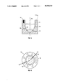
- FIGS. 2A and 2B represent a sectional view and a top view, respectively, of the conical piston belonging to the present invention.
- FIGS. 3A and 3B represent a sectional view and a top view, respectively, of the cap plate belonging to the present invention.
- FIG. 4 shows a preferred embodiment of the completely assembled O-ring testing apparatus.
- FIG. 5 shows an alternative embodiment, completely assembled, of the present invention.
- a preferred embodiment of the present invention comprises a housing, a conical piston, a pressurizing means, and a means for controlling movement of the conical piston relative to the housing.
- FIGS. 1A and 1B show a housing (10) of the present invention having a conical bore (12).
- the conical bore (12) tapers or inclines from a line parallel to a longitudinal axis (14) of the conical bore (12) at a predetermined angle (16). The angle is computed from the ratio of the desired magnitude of radial gap-opening to the desired magnitude of axial displacement.
- the housing also contains a variety of ports (18) which extend between an exterior surface (19) of the housing (10) and the conical bore (12). These ports (18) are located to facilitate pressurization where appropriate and to monitor the amount and rate of fluid leakage past the O-ring seals.
- FIGS. 2A and 2B show a conical piston (20) having a longitudinal axis (22).
- the conical piston (20) tapers or inclines from the longitudinal axis (22) at the same angle (16) as that of the conical bore (12) in the housing (10). The purpose of this angle is, here again, to produce a given amount of radial gap-opening for a given amount of axial displacement along the O-ring.
- the conical piston (20) also has a first gland (24) in which an O-ring gasket is placed for testing.
- a second gland (26) may be provided for a second O-ring gasket in order to contain or monitor secondary leakage subsequent to any leakage past the O-ring in the first gland (24)
- a third gland (28) may be provided to contain or monitor the amount of any leakage past the O-ring in the second gland (26).
- Each gland has a high pressure or upstream side and a low pressure or downstream side.
- a passageway (29) can be provided in the piston (20) through which a fluid at the desired temperature may be circulated to control the testing temperature.
- FIGS. 3A and 3B show a cap plate (30).
- the cap plate (30) functions as another part of the housing (10) and is used to enclose or restrain the conical piston (20) during testing.
- the cap plate (30) has an opening (32) through which the movement of the piston (20) is controlled.
- the cap plate may further have another passageway (34) to match the passageway (29) in the piston (20) to aid in temperature control.
- FIG. 4 shows the housing (10), the conical piston (20), and the cap plate (30) of the present invention completely assembled.
- the piston (20) is slidably mounted within the housing (10) such that the piston (20) is coaxial with the conical bore (12) of the housing (10).
- a chamber (41) is formed between the housing (10) and the piston (20).
- the chamber (41) is pressurized through a pressurization port (42) which extends between the chamber (41) and the exterior surface (19) of the housing (10).
- the ports (18) are usually arranged in the housing (10) so there is access to the spaces between the housing (10) and the piston (20) and between adjacent O-rings.
- the ports (18 and 42) are used for pressurization and to monitor any leakage which may occur. Leakage past the O-ring gasket may be detected with the use of a pressure transducer (46).
- FIG. 4 also shows a hydraulic actuator (43) attached to piston (20) as a means for controlling piston movement.
- the hydraulic actuator (43) may be used to control both the rate and magnitude of radial gap movement.
- shims (44) may be provided between the housing (10) and the piston (20) or between the housing (10) and the cap plate (30) as shown in FIG. 4.
- FIG. 4 further shows a displacement transducer (45) installed between the piston (20) and the housing (10).
- This transducer (45) is used to monitor the rate and amount of coaxial movement of the piston (20) relative to the housing (10).
- the housing (10) may be provided with a heating mechanism (not shown) to heat the O-rings to the desired temperature.
- An example of a heating mechanism would be to wrap the housing (10) with electrical heating strips (47).
- Cooling of the O-ring gaskets may be accomplished by passing a coolant such as liquid nitrogen through the passageways (FIG. 2, 29 and FIG. 3, 34) in the piston (20) and cap plate (30). Alternatively, cooling of the O-rings may be obtained by refrigerating the testing apparatus.
- FIG. 5 shows an alternative embodiment which may be better suited for testing larger diameter O-rings.
- This embodiment is basically the same as that shown in FIG. 4 except the housing is modified.
- the housing (10) has an opening (52) on the pressurization end (54) which is sealed with another O-ring gasket (56).
- Still another embodiment is where the housing and conical piston in the vicinity of the first gland can be separated from and reattached to the remainder of the housing and conical piston, respectively.
- Such a configuration has the advantage of allowing long term storage of the O-ring gasket under compression prior to testing while allowing continued use of the other parts. Thus, minimal duplication of the testing apparatus is attained where multiple tests are to be run which require long term compression of the O-ring prior to testing.
- the procedure for using the present invention is straight forward.
- the O-ring to be tested is placed in the first O-ring gland.
- Other O-rings are also placed on the remaining glands where necessary or desired as part of the first step.
- the O-rings may first be coated with a lubricant prior to placing them in the gland.
- shims may be selected to provide predetermined initial and final positions of the piston relative to the housing.
- the piston and the shims, if used are secured within the housing by attaching the cap plate to the housing.
- any desired instrumentation is connected to the test fixture.
- the chamber is pressurized at a selected rate to the desired maximum pressure.
- the rate of pressurization may also be coordinated with the rate of radial gap-opening. During pressurization, the performance of the O-ring gasket can be observed and recorded.
- the O-ring can be pressurized slightly from both sides prior to applying the test pressure.
Landscapes
- Physics & Mathematics (AREA)
- General Physics & Mathematics (AREA)
- Examining Or Testing Airtightness (AREA)
Abstract
An apparatus for testing O-ring gaskets under a variety of temperature, pressure, and dynamic loading conditions. Specifically, this apparatus has the ability to simulate a dynamic loading condition where the sealing surface in contact with the O-ring moves both away from and axially along the face of the O-ring.
Description
The invention described herein was made by employees of the United States Government and may be manufactured and used by or for the Government for governmental purposes without the payment of any royalties thereon or therefor.
This invention relates to a machine or apparatus. Specifically, this invention pertains to an apparatus for testing the sealing characteristics of O-ring gaskets under a variety of conditions.
Prior to the present invention, typical test fixtures for testing the sealing characteristics of O-ring gaskets used as bore seals were of two types. First, there was the totally static fixture. This fixture, as its name implies, checked O-ring performance under a totally static configuration, i.e., neither surface in contact with the O-ring was allowed to move. The second type was a partially dynamic test fixture. Under this configuration, one of the surfaces in contact with the O-ring was allowed to rotate with respect to the O-ring during the test. In addition, axial movement across the face of the O-ring could also be simulated with the second test fixture. However, neither fixture could check the response of an O-ring gasket where there was radial movement of the sealing surface away from the O-ring, i.e., where the space or gap filled by the O-ring became enlarged.
The present invention was first discussed in NASA test reports covering various results of testing performed on the invention. One report was dated January 1987 and the other one was dated Dec. 22, 1987. Both reports were authored by James E. Turner, a coinventor of the present invention, and were restricted to NASA personnel and NASA contractors only. The invention was first disclosed to the public at a conference in a paper entitled "Evaluation of the Sealing Ability of Various O-ring Materials for the Space Shuttle Redesigned Solid Rocket Motor," which was presented on June 7, 1988.
The present invention has the ability to test the sealing characteristics of O-ring gaskets under a variety of dynamic loading conditions. Where an O-ring is expected to perform a sealing function against a high-pressure fluid, the present invention allows the O-ring to be checked under various combinations of parameters. These parameters include (1) temperature, (2) pressure, (3) rate of pressurization, (4) magnitude of radial gap-opening, (5) rate of radial gap-opening, (6) pressurization as a function of gap-opening, and (7) position of the O-ring gasket in the O-ring gland prior to pressurization. The term "gap-opening" refers to the condition where the space filled by the O-ring enlarges due to some external force. Thus, where the installed O-ring has to react to some gap-opening in order to maintain an effective seal, the present invention has the capability to simulate both the maximum gap-opening expected to occur in practice and the rate at which the gap opens.
An object of the present invention is to check the sealing ability of an O-ring gasket as the sealing surface moves away from the O-ring.
Another object of this invention is to check the sealing ability of an O-ring gasket both as the sealing surface moves away from the O-ring and as the sealing surface slides in an axial direction across the face of the O-ring.
Further details of the present invention are explained below with the help of the attached drawings in which:
FIGS. 1A and 1B represent a sectional view and a top view, respectively, of the housing belonging to the present invention.
FIGS. 2A and 2B represent a sectional view and a top view, respectively, of the conical piston belonging to the present invention.
FIGS. 3A and 3B represent a sectional view and a top view, respectively, of the cap plate belonging to the present invention.
FIG. 4 shows a preferred embodiment of the completely assembled O-ring testing apparatus.
FIG. 5 shows an alternative embodiment, completely assembled, of the present invention.
A preferred embodiment of the present invention comprises a housing, a conical piston, a pressurizing means, and a means for controlling movement of the conical piston relative to the housing.
FIGS. 1A and 1B show a housing (10) of the present invention having a conical bore (12). The conical bore (12) tapers or inclines from a line parallel to a longitudinal axis (14) of the conical bore (12) at a predetermined angle (16). The angle is computed from the ratio of the desired magnitude of radial gap-opening to the desired magnitude of axial displacement. The housing also contains a variety of ports (18) which extend between an exterior surface (19) of the housing (10) and the conical bore (12). These ports (18) are located to facilitate pressurization where appropriate and to monitor the amount and rate of fluid leakage past the O-ring seals.
FIGS. 2A and 2B show a conical piston (20) having a longitudinal axis (22). The conical piston (20) tapers or inclines from the longitudinal axis (22) at the same angle (16) as that of the conical bore (12) in the housing (10). The purpose of this angle is, here again, to produce a given amount of radial gap-opening for a given amount of axial displacement along the O-ring. The conical piston (20) also has a first gland (24) in which an O-ring gasket is placed for testing. A second gland (26) may be provided for a second O-ring gasket in order to contain or monitor secondary leakage subsequent to any leakage past the O-ring in the first gland (24) A third gland (28) may be provided to contain or monitor the amount of any leakage past the O-ring in the second gland (26). Each gland has a high pressure or upstream side and a low pressure or downstream side. A passageway (29) can be provided in the piston (20) through which a fluid at the desired temperature may be circulated to control the testing temperature.
FIGS. 3A and 3B show a cap plate (30). The cap plate (30) functions as another part of the housing (10) and is used to enclose or restrain the conical piston (20) during testing. The cap plate (30) has an opening (32) through which the movement of the piston (20) is controlled. The cap plate may further have another passageway (34) to match the passageway (29) in the piston (20) to aid in temperature control.
FIG. 4 shows the housing (10), the conical piston (20), and the cap plate (30) of the present invention completely assembled. The piston (20) is slidably mounted within the housing (10) such that the piston (20) is coaxial with the conical bore (12) of the housing (10). With the piston (20) in the housing (10), a chamber (41) is formed between the housing (10) and the piston (20). During testing operations, the chamber (41) is pressurized through a pressurization port (42) which extends between the chamber (41) and the exterior surface (19) of the housing (10). The ports (18) are usually arranged in the housing (10) so there is access to the spaces between the housing (10) and the piston (20) and between adjacent O-rings. The ports (18 and 42) are used for pressurization and to monitor any leakage which may occur. Leakage past the O-ring gasket may be detected with the use of a pressure transducer (46).
FIG. 4 also shows a hydraulic actuator (43) attached to piston (20) as a means for controlling piston movement. The hydraulic actuator (43) may be used to control both the rate and magnitude of radial gap movement. To more precisely control the initial gap-opening and the final gap-opening, shims (44) may be provided between the housing (10) and the piston (20) or between the housing (10) and the cap plate (30) as shown in FIG. 4.
FIG. 4 further shows a displacement transducer (45) installed between the piston (20) and the housing (10). This transducer (45) is used to monitor the rate and amount of coaxial movement of the piston (20) relative to the housing (10). The housing (10) may be provided with a heating mechanism (not shown) to heat the O-rings to the desired temperature. An example of a heating mechanism would be to wrap the housing (10) with electrical heating strips (47). Cooling of the O-ring gaskets may be accomplished by passing a coolant such as liquid nitrogen through the passageways (FIG. 2, 29 and FIG. 3, 34) in the piston (20) and cap plate (30). Alternatively, cooling of the O-rings may be obtained by refrigerating the testing apparatus.
FIG. 5 shows an alternative embodiment which may be better suited for testing larger diameter O-rings. This embodiment is basically the same as that shown in FIG. 4 except the housing is modified. Here, the housing (10) has an opening (52) on the pressurization end (54) which is sealed with another O-ring gasket (56).
Still another embodiment (not shown) is where the housing and conical piston in the vicinity of the first gland can be separated from and reattached to the remainder of the housing and conical piston, respectively. Such a configuration has the advantage of allowing long term storage of the O-ring gasket under compression prior to testing while allowing continued use of the other parts. Thus, minimal duplication of the testing apparatus is attained where multiple tests are to be run which require long term compression of the O-ring prior to testing.
The procedure for using the present invention is straight forward. First, the O-ring to be tested is placed in the first O-ring gland. Other O-rings are also placed on the remaining glands where necessary or desired as part of the first step. If desired, the O-rings may first be coated with a lubricant prior to placing them in the gland. Second, shims may be selected to provide predetermined initial and final positions of the piston relative to the housing. Third, the piston and the shims, if used, are secured within the housing by attaching the cap plate to the housing. Fourth, any desired instrumentation is connected to the test fixture. Finally, after bringing the O-rings to the desired temperature by either heating or cooling the apparatus, the chamber is pressurized at a selected rate to the desired maximum pressure. The rate of pressurization may also be coordinated with the rate of radial gap-opening. During pressurization, the performance of the O-ring gasket can be observed and recorded.
If it is desired to properly center and seat the O-ring in the gland prior to checking its sealing characteristics, the O-ring can be pressurized slightly from both sides prior to applying the test pressure.
Claims (17)
1. An apparatus for testing O-ring gaskets, comprising:
a housing, said housing having a conical bore, said conical bore further having a longitudinal axis;
a conical piston having a longitudinal axis, said conical piston is located within said housing and said longitudinal axis of said conical piston is aligned with said longitudinal axis of said conical bore in said housing, whereby a chamber is formed between said housing and said conical piston, said conical piston also having a first gland for holding an O-ring gasket, said first gland having an upstream side and a downstream side;
a means for pressurizing said chamber; and
a means for controlling movement of said conical piston relative to said housing along said axes.
a means for detecting leakage past an O-ring gasket.
2. An apparatus for testing O-ring gaskets as recited in claim 1, wherein said means for detecting leakage comprises a pressure transducer.
3. An apparatus for testing O-ring gaskets as recited in claim 1, further comprising a means for measuring movement of said conical piston relative to said housing along said axes.
4. An apparatus for testing O-ring gaskets as recited in claim 3, wherein said means for measuring movement comprises a displacement transducer.
5. An apparatus for testing O-ring gaskets as recited in claim 1, further comprising a means for controlling temperature of said housing and said conical piston.
6. An apparatus for testing O-ring gaskets as recited in claim 5, wherein said means for controlling temperature comprises a passageway in said conical piston through which a fluid is circulated at a predetermined temperature.
7. An apparatus for testing O-ring gaskets as recited in claim 5, wherein said means for controlling temperature comprises an electrical heat strip wrapped around said housing.
8. An apparatus for testing O-ring gaskets as recited in claim 5, wherein said means for controlling temperature comprises cooling said housing and said conical piston with external refrigeration.
9. An apparatus for testing O-ring gaskets as recited in claim 1, wherein said means for pressurizing comprises a pressurization port having access to an area between said housing and said conical piston and adjacent to said upstream side of said first gland through which a fluid is supplied to said chamber under pressure.
10. An apparatus for testing O-ring gaskets as recited in claim 1, wherein said means for controlling movement comprises a hydraulic actuator attached to said conical piston.
11. An a for testing O-ring gaskets as recited in claim 1, further comprising a cap plate attached to said housing for restraining said conical piston during pressurization of said chamber.
12. An apparatus for testing O-ring gaskets as recited in claim 11, further comprising a first shim of a predetermined thickness located between .said conical piston and said housing for controlling an initial position of said conical piston relative to said housing.
13. An apparatus for testing O-ring gaskets as recited in claim 11, further comprising a second shim of a predetermined thickness located between said conical piston and said cap plate for controlling a final position of said conical piston relative to said housing.
14. An apparatus for testing O-ring gaskets as recited in claim 1, further comprising:
a second gland located adjacent to said downstream side of said first gland on said conical piston, said second gland having an upstream side and a downstream side; and
a primary leakage port in said housing, said primary leakage port having access to an area between said housing and said conical piston and between said first gland and said second gland.
15. An apparatus for testing O-ring gaskets as recited in claim 14, further comprising:
a third gland located adjacent to said downstream side of said second gland on said conical piston; and
a secondary leakage port in said housing, said secondary leakage port having access to an area between said housing and said conical piston and between said second gland and said third gland.
16. An apparatus for testing O-ring gaskets as recited in claim 1, wherein said housing has an opening adjacent to said chamber, and said chamber is sealed from said opening with an O-ring gasket.
17. An apparatus for testing O-ring gaskets as recited in claim 1,
wherein said conical piston comprises at least two parts, one of said two parts of said conical piston consisting of a portion of said piston having said first gland, and
wherein said housing comprises at least two parts, one of said two parts of said housing consisting of a portion of said housing adjacent to said first gland of said piston,
whereby said part of said piston having said first gland and said part of said housing adjacent to said first gland are capable of holding an O-ring gasket in compression for a period of time prior to testing.
Priority Applications (1)
| Application Number | Priority Date | Filing Date | Title |
|---|---|---|---|
| US07/361,479 US5000033A (en) | 1989-06-05 | 1989-06-05 | O-ring gasket test fixture |
Applications Claiming Priority (1)
| Application Number | Priority Date | Filing Date | Title |
|---|---|---|---|
| US07/361,479 US5000033A (en) | 1989-06-05 | 1989-06-05 | O-ring gasket test fixture |
Publications (1)
| Publication Number | Publication Date |
|---|---|
| US5000033A true US5000033A (en) | 1991-03-19 |
Family
ID=23422225
Family Applications (1)
| Application Number | Title | Priority Date | Filing Date |
|---|---|---|---|
| US07/361,479 Expired - Fee Related US5000033A (en) | 1989-06-05 | 1989-06-05 | O-ring gasket test fixture |
Country Status (1)
| Country | Link |
|---|---|
| US (1) | US5000033A (en) |
Cited By (19)
| Publication number | Priority date | Publication date | Assignee | Title |
|---|---|---|---|---|
| EP0609749A2 (en) * | 1993-01-28 | 1994-08-10 | Johnson Service Company | Test apparatus for seal members in a pressurized oxygen environment |
| US5629362A (en) * | 1995-05-31 | 1997-05-13 | Heatshield Technologies Inc. | Photon diffusive coating |
| US20080012236A1 (en) * | 2006-07-11 | 2008-01-17 | Declan Reilly | Packing case seal |
| KR100849115B1 (en) * | 2006-11-17 | 2008-07-30 | (주)플로엘텍 | O-ring tester |
| DE102007040864A1 (en) * | 2007-08-29 | 2009-01-02 | Tyco Electronics Amp Gmbh | Method and device for testing an electrical connection device with respect to tightness |
| DE102007032761A1 (en) * | 2007-07-13 | 2009-01-15 | Deutsches Zentrum für Luft- und Raumfahrt e.V. | Apparatus and method for testing a gasket intended for cryogenic application |
| WO2012036417A2 (en) * | 2010-09-17 | 2012-03-22 | 동우화인켐 주식회사 | Stereo image display |
| WO2012050432A3 (en) * | 2010-10-11 | 2012-06-07 | Bin Zainal Abidin Azhar | Mechanical seal static air test apparatus |
| CN104792508A (en) * | 2015-04-15 | 2015-07-22 | 中国航天科技集团公司川南机械厂 | Online compression amount measurement method for seal ring of small solid rocket |
| US20150233788A1 (en) * | 2015-05-06 | 2015-08-20 | Caterpillar Inc. | System and method for testing of seal materials |
| CN106353080A (en) * | 2016-08-30 | 2017-01-25 | 中国海洋大学 | Experimental device and experimental method for linear dynamic sealing characteristics of sealing rings |
| DE102015015443A1 (en) * | 2015-11-03 | 2017-05-04 | Sew-Eurodrive Gmbh & Co Kg | Device with housing for testing a shaft seal and method for testing a system |
| CN107560842A (en) * | 2017-10-30 | 2018-01-09 | 张旭 | A kind of rubber seal bearing capacity Auto-Test System |
| CN107764485A (en) * | 2017-08-30 | 2018-03-06 | 武汉船用机械有限责任公司 | A kind of full-rotating rudder paddle dynamic sealing experimental rig |
| US10429274B2 (en) * | 2017-05-31 | 2019-10-01 | Southwest Petrolem Univeristy | Vertical high speed testing device for spiral seal of cone bit bearing |
| CN110940470A (en) * | 2019-10-15 | 2020-03-31 | 西北工业大学 | Rubber seal performance testing device |
| CN112629847A (en) * | 2021-01-06 | 2021-04-09 | 四川云游九天科技有限公司 | O-shaped ring sealing resistance experiment platform and sealing resistance test method |
| WO2021103040A1 (en) * | 2019-11-26 | 2021-06-03 | 深圳大学 | Testing apparatus and testing method for high-pressure sealing ring |
| CN114252257A (en) * | 2021-12-13 | 2022-03-29 | 安庆帝伯功能塑料有限公司 | Dynamic sealing ring testing machine |
Citations (1)
| Publication number | Priority date | Publication date | Assignee | Title |
|---|---|---|---|---|
| US3213674A (en) * | 1962-08-15 | 1965-10-26 | Manuel S Salcido | Tool |
-
1989
- 1989-06-05 US US07/361,479 patent/US5000033A/en not_active Expired - Fee Related
Patent Citations (1)
| Publication number | Priority date | Publication date | Assignee | Title |
|---|---|---|---|---|
| US3213674A (en) * | 1962-08-15 | 1965-10-26 | Manuel S Salcido | Tool |
Cited By (30)
| Publication number | Priority date | Publication date | Assignee | Title |
|---|---|---|---|---|
| EP0609749A2 (en) * | 1993-01-28 | 1994-08-10 | Johnson Service Company | Test apparatus for seal members in a pressurized oxygen environment |
| US5339678A (en) * | 1993-01-28 | 1994-08-23 | Johnson Service Company | Test apparatus for seal members in a pressurized oxygen environment |
| EP0609749A3 (en) * | 1993-01-28 | 1995-01-18 | Johnson Service Co | Test apparatus for seal members in a pressurized oxygen environment. |
| US5629362A (en) * | 1995-05-31 | 1997-05-13 | Heatshield Technologies Inc. | Photon diffusive coating |
| US20080012236A1 (en) * | 2006-07-11 | 2008-01-17 | Declan Reilly | Packing case seal |
| KR100849115B1 (en) * | 2006-11-17 | 2008-07-30 | (주)플로엘텍 | O-ring tester |
| DE102007032761A1 (en) * | 2007-07-13 | 2009-01-15 | Deutsches Zentrum für Luft- und Raumfahrt e.V. | Apparatus and method for testing a gasket intended for cryogenic application |
| DE102007040864A1 (en) * | 2007-08-29 | 2009-01-02 | Tyco Electronics Amp Gmbh | Method and device for testing an electrical connection device with respect to tightness |
| WO2012036417A2 (en) * | 2010-09-17 | 2012-03-22 | 동우화인켐 주식회사 | Stereo image display |
| WO2012036417A3 (en) * | 2010-09-17 | 2012-06-07 | 동우화인켐 주식회사 | Stereo image display |
| WO2012050432A3 (en) * | 2010-10-11 | 2012-06-07 | Bin Zainal Abidin Azhar | Mechanical seal static air test apparatus |
| CN104792508B (en) * | 2015-04-15 | 2017-05-03 | 中国航天科技集团公司川南机械厂 | Online compression amount measurement method for seal ring of small solid rocket |
| CN104792508A (en) * | 2015-04-15 | 2015-07-22 | 中国航天科技集团公司川南机械厂 | Online compression amount measurement method for seal ring of small solid rocket |
| US20150233788A1 (en) * | 2015-05-06 | 2015-08-20 | Caterpillar Inc. | System and method for testing of seal materials |
| DE102015015443A1 (en) * | 2015-11-03 | 2017-05-04 | Sew-Eurodrive Gmbh & Co Kg | Device with housing for testing a shaft seal and method for testing a system |
| DE102015015443B4 (en) | 2015-11-03 | 2021-12-02 | Sew-Eurodrive Gmbh & Co Kg | Device with housing for testing a shaft seal and method for testing a system |
| CN106353080A (en) * | 2016-08-30 | 2017-01-25 | 中国海洋大学 | Experimental device and experimental method for linear dynamic sealing characteristics of sealing rings |
| CN106353080B (en) * | 2016-08-30 | 2019-02-15 | 中国海洋大学 | A kind of sealing ring straight line dynamic sealing characteristic experimental apparatus and experimental method |
| US10429274B2 (en) * | 2017-05-31 | 2019-10-01 | Southwest Petrolem Univeristy | Vertical high speed testing device for spiral seal of cone bit bearing |
| CN107764485B (en) * | 2017-08-30 | 2019-10-18 | 武汉船用机械有限责任公司 | A kind of full-rotating rudder paddle dynamic sealing experimental rig |
| CN107764485A (en) * | 2017-08-30 | 2018-03-06 | 武汉船用机械有限责任公司 | A kind of full-rotating rudder paddle dynamic sealing experimental rig |
| CN107560842A (en) * | 2017-10-30 | 2018-01-09 | 张旭 | A kind of rubber seal bearing capacity Auto-Test System |
| CN107560842B (en) * | 2017-10-30 | 2019-03-22 | 鬼怒川橡塑(广州)有限公司 | A kind of rubber seal bearing capacity Auto-Test System |
| CN110940470A (en) * | 2019-10-15 | 2020-03-31 | 西北工业大学 | Rubber seal performance testing device |
| CN110940470B (en) * | 2019-10-15 | 2021-10-26 | 西北工业大学 | Rubber seal performance testing device |
| WO2021103040A1 (en) * | 2019-11-26 | 2021-06-03 | 深圳大学 | Testing apparatus and testing method for high-pressure sealing ring |
| CN112629847A (en) * | 2021-01-06 | 2021-04-09 | 四川云游九天科技有限公司 | O-shaped ring sealing resistance experiment platform and sealing resistance test method |
| CN112629847B (en) * | 2021-01-06 | 2023-09-29 | 四川云游九天科技有限公司 | O-shaped ring sealing resistance experiment platform and sealing resistance test method |
| CN114252257A (en) * | 2021-12-13 | 2022-03-29 | 安庆帝伯功能塑料有限公司 | Dynamic sealing ring testing machine |
| CN114252257B (en) * | 2021-12-13 | 2023-11-03 | 安庆帝伯功能塑料有限公司 | Dynamic sealing ring testing machine |
Similar Documents
| Publication | Publication Date | Title |
|---|---|---|
| US5000033A (en) | O-ring gasket test fixture | |
| US5339678A (en) | Test apparatus for seal members in a pressurized oxygen environment | |
| JPS60256026A (en) | Nondestructive inspection device for safety of tubular member | |
| US3606356A (en) | High-pressure seal assembly | |
| US4418918A (en) | Static seal device with plastically deformable metal for cryogenic refrigerators | |
| US2452292A (en) | Pressure intensifier | |
| US4557487A (en) | Hybrid seal with both static and dynamic seal rings | |
| CA3198125A1 (en) | A pipe testing apparatus and method | |
| US5081862A (en) | Apparatus and method for pressure testing closure disks | |
| US3962956A (en) | Hydropneumatic valve actuator | |
| US4318572A (en) | Tension-compression swivel joint with hydraulic force reaction | |
| Turner et al. | O-ring gasket test fixture | |
| US4149404A (en) | Pressure testing of rocket motor cases | |
| JP3624745B2 (en) | Seal device for leak test equipment | |
| US6543468B2 (en) | Instrument installation and method for testing imperviousness in a high pressure process | |
| US5062303A (en) | Encapsulated actuator for testing of specimens | |
| US3545343A (en) | Welded fluid seal | |
| US6145846A (en) | Metal-to-metal seal in high pressure applications with low contact stress | |
| US2780092A (en) | Tube testing device | |
| US3548646A (en) | Tensile test apparatus | |
| JP2829843B2 (en) | Pipe and flange weld inspection equipment | |
| US4266467A (en) | Differential pressure limiting valve | |
| CA2510666A1 (en) | Device for connecting pipelines such that relative motion is allowed, comprising a pretensioning device such that constant sealing gap can be provided | |
| US5109712A (en) | Portable sample cylinder with reduced seal permeability | |
| CLINTON et al. | Long-term compression effects on elastomeric O-ring behavior |
Legal Events
| Date | Code | Title | Description |
|---|---|---|---|
| AS | Assignment |
Owner name: UNITED STATES OF AMERICA, THE, AS REPRESENTED BY T Free format text: ASSIGNMENT OF ASSIGNORS INTEREST.;ASSIGNORS:TURNER, JAMES E.;MC CLUNEY, DONALD S.;REEL/FRAME:005087/0718 Effective date: 19890525 |
|
| REMI | Maintenance fee reminder mailed | ||
| LAPS | Lapse for failure to pay maintenance fees | ||
| FP | Lapsed due to failure to pay maintenance fee |
Effective date: 19950322 |
|
| STCH | Information on status: patent discontinuation |
Free format text: PATENT EXPIRED DUE TO NONPAYMENT OF MAINTENANCE FEES UNDER 37 CFR 1.362 |