US4991961A - Moving mirror tilt adjust mechanism in an interferometer - Google Patents
Moving mirror tilt adjust mechanism in an interferometer Download PDFInfo
- Publication number
- US4991961A US4991961A US07/357,526 US35752689A US4991961A US 4991961 A US4991961 A US 4991961A US 35752689 A US35752689 A US 35752689A US 4991961 A US4991961 A US 4991961A
- Authority
- US
- United States
- Prior art keywords
- block
- links
- mirror
- housing
- adjust
- Prior art date
- Legal status (The legal status is an assumption and is not a legal conclusion. Google has not performed a legal analysis and makes no representation as to the accuracy of the status listed.)
- Expired - Lifetime
Links
- 230000005855 radiation Effects 0.000 description 6
- 238000005033 Fourier transform infrared spectroscopy Methods 0.000 description 5
- 230000003287 optical effect Effects 0.000 description 4
- 238000001228 spectrum Methods 0.000 description 4
- 230000000694 effects Effects 0.000 description 2
- 238000001157 Fourier transform infrared spectrum Methods 0.000 description 1
- 238000010521 absorption reaction Methods 0.000 description 1
- 238000004458 analytical method Methods 0.000 description 1
- 150000001875 compounds Chemical class 0.000 description 1
- 238000010276 construction Methods 0.000 description 1
- 239000010437 gem Substances 0.000 description 1
- 229910001751 gemstone Inorganic materials 0.000 description 1
- 239000003292 glue Substances 0.000 description 1
- 238000010348 incorporation Methods 0.000 description 1
- 238000002329 infrared spectrum Methods 0.000 description 1
- 238000003754 machining Methods 0.000 description 1
- 238000000034 method Methods 0.000 description 1
- 230000000737 periodic effect Effects 0.000 description 1
- 239000007787 solid Substances 0.000 description 1
- 239000000126 substance Substances 0.000 description 1
- 239000000725 suspension Substances 0.000 description 1
Images


Classifications
-
- G—PHYSICS
- G02—OPTICS
- G02B—OPTICAL ELEMENTS, SYSTEMS OR APPARATUS
- G02B7/00—Mountings, adjusting means, or light-tight connections, for optical elements
- G02B7/18—Mountings, adjusting means, or light-tight connections, for optical elements for prisms; for mirrors
- G02B7/182—Mountings, adjusting means, or light-tight connections, for optical elements for prisms; for mirrors for mirrors
- G02B7/1822—Mountings, adjusting means, or light-tight connections, for optical elements for prisms; for mirrors for mirrors comprising means for aligning the optical axis
- G02B7/1824—Manual alignment
- G02B7/1825—Manual alignment made by screws, e.g. for laser mirrors
-
- G—PHYSICS
- G01—MEASURING; TESTING
- G01J—MEASUREMENT OF INTENSITY, VELOCITY, SPECTRAL CONTENT, POLARISATION, PHASE OR PULSE CHARACTERISTICS OF INFRARED, VISIBLE OR ULTRAVIOLET LIGHT; COLORIMETRY; RADIATION PYROMETRY
- G01J3/00—Spectrometry; Spectrophotometry; Monochromators; Measuring colours
- G01J3/28—Investigating the spectrum
- G01J3/45—Interferometric spectrometry
- G01J3/453—Interferometric spectrometry by correlation of the amplitudes
- G01J3/4535—Devices with moving mirror
Definitions
- the present invention pertains generally to the field of moving mirror tilt adjustment such as that used in Fourier transform interferometric spectrometers to maintain orthogonality between the moving mirror and the direction of motion of the moving mirror in such spectrometers.
- FTIR Fourier transform infrared
- the detector It is the function of the detector to convert this time variant intensity signal to a corresponding time varying current.
- the current is converted to a time varying voltage, which is presented to an analog-to-digital converter and then stored as a sequence of digital numbers to be processed in a processor associated with the spectrometer.
- the moving mirror element that modulates the analytical radiation used by the instrument to study samples.
- the moving mirror allows a time-domain interferogram to be generated which, when analyzed, allows high resolution frequency-domain spectra to be produced.
- the computer performs a Fourier transform on the data to produce a spectrum which shows spectral-energy versus frequency.
- the surface of the moving mirror be very accurately held in an orthogonal position, i.e., at a right angle, to the direction of the motion of the moving mirror.
- Positional accuracy of the moving mirror is crucial because deviations in the mirror alignment produce small errors in the time-domain interferogram that may translate into large errors in the frequency-domain spectrum.
- deviations of the moving mirror larger than one wavelength of the analytical radiation used are considered significant and can seriously degrade the quality of the entire instrument.
- the moving mirror is mounted upon an arm that is guided along its line of motion by suspension from two links spaced a distance apart.
- the links are pivotably attached to the mirror arm and to the housing of the interferometer at pivots, thus forming a parallelogram.
- Such an arrangement is sometimes referred to as a "porch swing" style of interferometer because of the likeness of its movement to its namesake.
- the moving mirror may be tilted along its path of motion, thus introducing errors into the spectrum.
- the two horizontal members must be of equal length, as must the vertical members (the links), in order to keep the mirror from tilting during travel.
- One prior art design uses adjusting collets at one of the pivot points along the mirror arm to fine tune the lengths of the horizontal and vertical members. There are, however, problems associated with the use of such collets to make adjustments to correct for mirror tilt.
- the adjustments are made on the moving portion of the mechanism, so that the mirror motion must be stopped for each adjustment iteration and then restarted to check the resulting tilt.
- the collet adjustment is non-linear, so that the results of each adjustment iteration are not necessarily predictable.
- the collets are held in place by set screws that must be loosened and re-tightened with each adjustment. However, the tightening of the set screws themselves affects the alignment.
- the present invention provides an accurate, time-saving, and predictable adjustment mechanism for the correction of tilt in the moving mirror of an interferometer of the "porch swing" type.
- One of the pivots of the housing from which a link is suspended is mounted in an adjustable block.
- the block is capable of moving relative to the other pivots, thus providing a means of enabling a user to minimize tilt.
- the block may be used to adjust the distance between the pivots in the housing to match the distance between the pivots in the mirror arm. This is correction of "vertical" tilt.
- the block may also be moved to compensate for any angular differences that would prevent the links from swinging in the same plane of motion. This is correction of "horizontal" tilt.
- the less critical pivot-to-pivot distance within each link can be adequately controlled using close tolerance machining methods.
- the adjustable block is moved to compensate for vertical tilt by the turning of an adjust screw that simultaneously moves a cam against an inclined surface of the adjustable block. This alters the pivot-to-pivot distance of the pivots in the housing.
- the adjustable block is moved to compensate for horizontal tilt by the turning of a second adjust screw that rotates the adjustable block in a manner that will bring the links into and out of parallel alignment. Since the adjustment mechanism is located on a fixed portion of the parallelogram, i.e. the housing, the mirror tilt adjustments can be performed while the mirror is in motion. This eliminates the necessity of painstaking iterations and allows one to immediately ascertain the effects of any adjustments. The correction of the vertical tilt is further facilitated in that a linear relationship is involved.
- FIG. 1 is a perspective view of a interferometer modulator that uses the moving mirror tilt adjust mechanism of the present invention.
- FIG. 2 is a front plan view of a interferometer modulator that uses the moving mirror tilt adjust mechanism of the present invention.
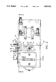
- FIG. 3 is a cross-sectional view along line 3--3 of FIG. 2.
- FIG. 4 is a cross-sectional view along line 4--4 of FIG. 2.
- FIG. 5 is a cross-sectional view along line 5--5 of FIG. 4.
- FIG. 6 is a perspective view of an H-shaped link suitable for use in the present invention.
- FIG. 7 is a perspective view of a mirror arm suitable for use in the present invention.
- FIG. 8 is a detail view of a pivot suitable for use in the present invention.
- FIGS. 1 and 2 show a modulator 10 used in an FTIR spectrometer that modulates the analytical radiation used by the instrument to study samples and uses the moving mirror tilt adjust mechanism of the present invention.
- the spectrometer is an interferometer of the "porch swing38 type.
- FIGS. 3, 4, and 5 are various cross-sections through the modulator 10 showing a housing 12 that encloses a moving mirror 14 (shown in FIG. 5) and associated parts necessary to adjust the tilt of the moving mirror 14. As best shown in FIG. 5, the moving mirror 14 is attached to a first end 16 of a rigid mirror arm 18.
- a suitable means for attaching the moving mirror 14 to the mirror arm 18 is to glue the moving mirror 14 to a holder 20, which is in turn secured to the mirror arm 18 by screws 22.
- the second end 24 of the mirror arm 18 is attached to a modulator motor 26 comprising a coil 28, a pole piece 30, a magnet 32, and a motor housing 33.
- the mirror arm 18 is suspended from the housing 12 by links 34 and 36, each of which have a first end 38 and a second end 40.
- the first ends 38 of each of the links 34 and 36 are attached to the mirror arm 18 by swinging pivots 42 and 44, respectively.
- Each of the links 34 and 36 are preferably H-shaped, as best shown in FIG.
- the interferometer must be free of natural vibration resonances in the FTIR spectrum range of interest (100-4,000 cm -1 ).
- the use of H-shaped links provides maximum mechanical stiffness and eliminates motion about undesirable axes which would result in undesirable vibrational resonances.
- the second ends 40 of each of the links 34 and 36 are attached to the adjustable block 68 and the housing 12 by fixed pivots 46 and 48, respectively. It is noted that there are two each of the pivots 42, 44, 46, and 48, in that the first and second ends 38 and 40 of the links 34 and 36 are forked by reason of the H-shaped configuration.
- FIG. 6 shows a perspective of a typical link 34 or 36 that is unattached to either the mirror arm 18 or the housing 12.
- FIG. 7 shows an unassembled mirror arm 18.
- the mirror arm 18 is driven linear to movement by the motor 26 and the path of the mirror arm 18 is guided by the links 34 and 36.
- the maximum range of travel of the moving mirror 14 and the mirror arm 18 is dictated by a first limit assembly 50.
- the first limit assembly 50 includes a plate 52, two adjust screws 54 and 56, and two bumpers 58 and 60.
- the second end 40 of the link 36 extends through two openings 62 (visible in FIG. 4) to the exterior of the housing 12 and the plate 52 is mounted thereupon.
- the adjust screws 54 and 56 are threaded through the plate 52.
- the bumpers 58 and 60 are mounted upon the exterior of the housing 12 beneath the adjust screws 54 and 56, respectively.
- a second limit assembly 67 is formed by a flag 69 that protrudes from the mirror arm 18 and a set of optical switches 71.
- the flag 69 is best depicted in FIG. 7 and the optical switches are best shown in FIG. 3.
- the flag 69 has a cutout region 73 with edges 75 and 77. When either of the edges 75 and 77 cut a light beam from one of the optical switches, a signal is sent to servo control to reverse the direction of the motor 26, and thus the mirror arm 18.
- the range of motion allowed by the second limit assembly 67 is the travel of the mirror arm 18 between which light from the optical switches 71 is not cut off by the edges 75 and 77.
- the first limit assembly 50 acts as a means of protecting the modulator 10 in the event that the second limit assembly 67 fails.
- the fixed pivots 46 and 48 which join the respective links 34 and 36 to the housing 12 are best shown in FIG. 4.
- the housing 12 includes a block 68 in which the pivot 46 is mounted.
- the block 68 is positioned within an aperture 70 of the housing 12.
- the block 68 is bounded and held in place within the aperture 70 by spring plungers 72 and 74, adjust screw 76, and a cam 80.
- the position of the cam 80 is adjustable by the turning of an adjust screw 82 that is threaded through the housing 12 and which abuts against the cam 80.
- a spring plunger 84 is mounted to bias the cam 80 against the adjust screw 82.
- the surface of the block 68 that contacts the cam 80 is inclined relative to the travel of the cam 80 so that the turning of the adjust screw 82 causes movement of the block 68 that alters the distance between the pivots fixed 46 and 48.
- the spring plunger 74 biases the block 68 against the cam 80.
- the position of the block 68 may also be adjusted by the turning of the adjust screw 76.
- the turning of the adjust screw 76 rotates the block 68 clockwise or counter clockwise in the orientation of FIG. 4 so that the links 34 and 36 may be brought into and out of the same plane of motion.
- the spring plunger 72 biases the block 68 against the adjust screw 76.
- the position of the pivot 48 remains stationary and is not adjustable.
- Rotational flexural pivots provide the best mechanism repeatability due to their inherent zero friction spring action. Bearings, either jewel or precision ball/roller, can be used as a less expensive alternative. Bearings would generate some frictional losses but would also eliminate the opposing spring force and limited motion range of the flexured pivots.
- An exemplary flexural of pivot is a "Free Flex Flexural Pivot" made by Lucas Aerospace. Such pivots, common in the art, have a fixed mount section and a load section.
- the load sections of the pivots 42, 44, 46, and 48 should be mounted within the links 34 and 36.
- the fixed mount section should be mounted within either the housing 12 or the mirror arm 18, as applicable.
- screws 86 are used to secure the pivots 42, 44, 46, and 48.
- the screws 86 are tightened sufficiently to secure but not distort the pivots.
- FIG. 8 shows a detail of one of the pivots 42, 44, 46, and 48.
- the pivots 42, 44, 46, and 48 are mounted so that small gaps 88 are horizontally aligned and so that the solid joint of the pivot is "up" or non-weight bearing.
- Adjustments made to the block 68 enable the user to horizontally and vertically align the moving mirror 14 so that the mirror 14 remains perpendicular to its line of motion.
- "vertical" tilt is the tilt of the mirror about the x-axis. Tilt about the x-axis is referred to as vertical because of a resultant periodic vertical image shift in the autocollimator (not shown) of the spectrometer with each mirror swing.
- the turning of the adjust screw 82 changes the distance between pivots fixed 46 and 48 relative to the swinging pivots 42 and 44. When the former pivot-to-pivot distance matches the latter pivot-to-pivot distance, the mirror tilt about the x-axis is minimized.
- “Horizontal tilt” refers to tilt about the z-axis. Horizontal tilt results from the links 34 and 36 not being parallel throughout the range of movement of the mirror arm 18, i.e., the links 34 and 36 do not swing in the same plane of motion.
- the turning of the adjust screw 76 rotates the block 68 clockwise or counterclockwise in the x-y plane to compensate for any angular differences that would prevent the links 34 and 36 from swinging in the same plane of motion. Thus, tilt about the z-axis is minimized.
- the tilt adjustment mechanism can be designed with only a horizontal tilt adjustment or only a vertical tilt adjustment.
Abstract
Description
Claims (30)
Priority Applications (4)
| Application Number | Priority Date | Filing Date | Title |
|---|---|---|---|
| US07/357,526 US4991961A (en) | 1989-05-26 | 1989-05-26 | Moving mirror tilt adjust mechanism in an interferometer |
| DE69010573T DE69010573D1 (en) | 1989-05-26 | 1990-05-02 | Adjustment device for the inclination of a movement mirror in an interferometer. |
| EP90304802A EP0399683B1 (en) | 1989-05-26 | 1990-05-02 | Moving mirror tilt adjust mechanism in an interferometer |
| JP2136903A JPH03103728A (en) | 1989-05-26 | 1990-05-25 | Mechanism for adjusting inclination of movable mirror of spectrometer |
Applications Claiming Priority (1)
| Application Number | Priority Date | Filing Date | Title |
|---|---|---|---|
| US07/357,526 US4991961A (en) | 1989-05-26 | 1989-05-26 | Moving mirror tilt adjust mechanism in an interferometer |
Publications (1)
| Publication Number | Publication Date |
|---|---|
| US4991961A true US4991961A (en) | 1991-02-12 |
Family
ID=23405987
Family Applications (1)
| Application Number | Title | Priority Date | Filing Date |
|---|---|---|---|
| US07/357,526 Expired - Lifetime US4991961A (en) | 1989-05-26 | 1989-05-26 | Moving mirror tilt adjust mechanism in an interferometer |
Country Status (4)
| Country | Link |
|---|---|
| US (1) | US4991961A (en) |
| EP (1) | EP0399683B1 (en) |
| JP (1) | JPH03103728A (en) |
| DE (1) | DE69010573D1 (en) |
Cited By (19)
| Publication number | Priority date | Publication date | Assignee | Title |
|---|---|---|---|---|
| US5457531A (en) * | 1993-06-17 | 1995-10-10 | Temet Instruments Oy | Movable mirror mounting mechanism in a scanning interferometer |
| US5459572A (en) * | 1993-06-17 | 1995-10-17 | Temet Instruments Oy | Mirror arrangement in a focusing interferometer |
| US5537208A (en) * | 1990-12-19 | 1996-07-16 | U.S. Philips Corporation | Interferometer spectrometer having means for varying the optical path length while maintaining alignment |
| US5949543A (en) * | 1997-11-12 | 1999-09-07 | Plx, Inc. | Monolithic optical assembly and associated retroreflector with beamsplitter assembly |
| US6141101A (en) * | 1997-11-12 | 2000-10-31 | Plx, Inc. | Monolithic optical assembly |
| US20030035116A1 (en) * | 2001-06-19 | 2003-02-20 | Fuyuhiko Inoue | Interferometer system |
| US6667808B2 (en) | 2000-03-08 | 2003-12-23 | Thermo Electron Scientific Instruments Corporation | Multifunctional fourier transform infrared spectrometer system |
| US20070086006A1 (en) * | 2005-10-18 | 2007-04-19 | Ebersole Matthew D | Spectrometer for analysis of multiple samples |
| US20100012808A1 (en) * | 2008-07-17 | 2010-01-21 | Plx, Inc. | Flexure mount for an optical assembly |
| US20100033728A1 (en) * | 2008-08-06 | 2010-02-11 | Plx, Inc. | Monolithic interferometer with optics of different material |
| US20130270461A1 (en) * | 2012-04-13 | 2013-10-17 | Kla-Tencor Corporation | Smart memory alloys for an extreme ultra-violet (euv) reticle inspection tool |
| US8827470B2 (en) | 2006-04-12 | 2014-09-09 | Plx, Inc. | Mount for an optical structure and method of mounting an optical structure using such mount |
| US8851689B2 (en) | 2012-07-27 | 2014-10-07 | Plx, Inc. | Interferometer, and optical assembly each having a three-pin mount for mounting an optical element at at least three points or areas and method of mounting same |
| US9097586B2 (en) | 2011-11-23 | 2015-08-04 | Plx, Inc. | Quasi-translator, fourier modulator, fourier spectrometer, motion control system and methods for controlling same, and signal processor circuit |
| US9377600B2 (en) | 2013-02-21 | 2016-06-28 | Plx, Inc. | Mounts for an optical structure having a grooved protruding member with a damping ring disposed in or on the groove and methods of mounting an optical structure using such mounts |
| US9513168B2 (en) | 2014-09-23 | 2016-12-06 | Utah State University Research Foundation | Linear-motion stage |
| US9798051B2 (en) | 2011-02-28 | 2017-10-24 | Plx, Inc. | Mount for an optical structure having a grooved protruding member and method of mounting an optical structure using such mount |
| US20180073927A1 (en) * | 2015-03-13 | 2018-03-15 | Shimadzu Corporation | Fourier transform type spectrophotometer |
| CN115615550A (en) * | 2022-10-21 | 2023-01-17 | 中船重工安谱(湖北)仪器有限公司 | Linear moving mirror mechanism |
Families Citing this family (5)
| Publication number | Priority date | Publication date | Assignee | Title |
|---|---|---|---|---|
| DE69220261T2 (en) * | 1991-03-01 | 1997-11-27 | Analect Instr Inc | Three-dimensional interferometer structure with scanning by refractive elements |
| EP0587284A3 (en) * | 1992-09-10 | 1994-03-30 | Nicolet Instrument Corporation | Interferometer and beamsplitter holder therefor |
| US7167325B2 (en) * | 2004-02-11 | 2007-01-23 | Agilent Technologies, Inc. | Flexured athermalized pseudokinematic mount |
| CN111123468A (en) * | 2019-12-30 | 2020-05-08 | 中国科学院长春光学精密机械与物理研究所 | Three-axial adjustable prism mounting table |
| CN112729047B (en) * | 2020-12-30 | 2022-05-13 | 山东仕达思医疗科技有限公司 | Parallelism adjusting method |
Citations (6)
| Publication number | Priority date | Publication date | Assignee | Title |
|---|---|---|---|---|
| US3936193A (en) * | 1974-02-13 | 1976-02-03 | Eocom Corporation | Multiplex interferometer |
| US4383762A (en) * | 1980-02-14 | 1983-05-17 | Kayser-Threde Gmbh | Two-beam interferometer for Fourier spectroscopy with rigid pendulum |
| US4556316A (en) * | 1983-03-01 | 1985-12-03 | Laser Precision Corporation | Interferometer spectrometer having simplified scanning motion control |
| US4693603A (en) * | 1985-10-21 | 1987-09-15 | Midac Corporation | Ruggedized compact interferometer requiring minimum isolation from mechanical vibrations |
| US4710001A (en) * | 1986-11-21 | 1987-12-01 | Hewlett-Packard Company | Support for a moving mirror in an interferometer |
| US4881814A (en) * | 1988-09-02 | 1989-11-21 | The Perkin-Elmer Corporation | Scanning Michelson interferometer assembly |
Family Cites Families (1)
| Publication number | Priority date | Publication date | Assignee | Title |
|---|---|---|---|---|
| US4573794A (en) * | 1983-03-03 | 1986-03-04 | Covey Joel P | Analytical instrument optical element support system |
-
1989
- 1989-05-26 US US07/357,526 patent/US4991961A/en not_active Expired - Lifetime
-
1990
- 1990-05-02 DE DE69010573T patent/DE69010573D1/en not_active Expired - Lifetime
- 1990-05-02 EP EP90304802A patent/EP0399683B1/en not_active Expired - Lifetime
- 1990-05-25 JP JP2136903A patent/JPH03103728A/en active Pending
Patent Citations (6)
| Publication number | Priority date | Publication date | Assignee | Title |
|---|---|---|---|---|
| US3936193A (en) * | 1974-02-13 | 1976-02-03 | Eocom Corporation | Multiplex interferometer |
| US4383762A (en) * | 1980-02-14 | 1983-05-17 | Kayser-Threde Gmbh | Two-beam interferometer for Fourier spectroscopy with rigid pendulum |
| US4556316A (en) * | 1983-03-01 | 1985-12-03 | Laser Precision Corporation | Interferometer spectrometer having simplified scanning motion control |
| US4693603A (en) * | 1985-10-21 | 1987-09-15 | Midac Corporation | Ruggedized compact interferometer requiring minimum isolation from mechanical vibrations |
| US4710001A (en) * | 1986-11-21 | 1987-12-01 | Hewlett-Packard Company | Support for a moving mirror in an interferometer |
| US4881814A (en) * | 1988-09-02 | 1989-11-21 | The Perkin-Elmer Corporation | Scanning Michelson interferometer assembly |
Cited By (33)
| Publication number | Priority date | Publication date | Assignee | Title |
|---|---|---|---|---|
| US5537208A (en) * | 1990-12-19 | 1996-07-16 | U.S. Philips Corporation | Interferometer spectrometer having means for varying the optical path length while maintaining alignment |
| US5457531A (en) * | 1993-06-17 | 1995-10-10 | Temet Instruments Oy | Movable mirror mounting mechanism in a scanning interferometer |
| US5459572A (en) * | 1993-06-17 | 1995-10-17 | Temet Instruments Oy | Mirror arrangement in a focusing interferometer |
| US5949543A (en) * | 1997-11-12 | 1999-09-07 | Plx, Inc. | Monolithic optical assembly and associated retroreflector with beamsplitter assembly |
| US6141101A (en) * | 1997-11-12 | 2000-10-31 | Plx, Inc. | Monolithic optical assembly |
| US6667808B2 (en) | 2000-03-08 | 2003-12-23 | Thermo Electron Scientific Instruments Corporation | Multifunctional fourier transform infrared spectrometer system |
| US20030035116A1 (en) * | 2001-06-19 | 2003-02-20 | Fuyuhiko Inoue | Interferometer system |
| US6813022B2 (en) | 2001-06-19 | 2004-11-02 | Nikon Corporation | Interferometer system |
| US20070086006A1 (en) * | 2005-10-18 | 2007-04-19 | Ebersole Matthew D | Spectrometer for analysis of multiple samples |
| US7339668B2 (en) | 2005-10-18 | 2008-03-04 | Thermo Electron Scientific Instruments Llc | Spectrometer for analysis of multiple samples |
| US8827468B2 (en) | 2006-04-12 | 2014-09-09 | Plx, Inc. | Mount for an optical structure and methods of mounting an optical structure using such mount |
| US8827470B2 (en) | 2006-04-12 | 2014-09-09 | Plx, Inc. | Mount for an optical structure and method of mounting an optical structure using such mount |
| US8205853B2 (en) | 2008-07-17 | 2012-06-26 | Ftrx Llc | Flexure mount for an optical assembly |
| US20100012808A1 (en) * | 2008-07-17 | 2010-01-21 | Plx, Inc. | Flexure mount for an optical assembly |
| US8205852B2 (en) | 2008-07-17 | 2012-06-26 | Ftrx Llc | Flexure mount for an optical assembly |
| US8120853B2 (en) * | 2008-08-06 | 2012-02-21 | Ftrx Llc | Optical assembly, method for assembling an optical assembly, system for securing optical elements of an optical assembly and a spring for securing optical elements of an optical assembly |
| US7995208B2 (en) | 2008-08-06 | 2011-08-09 | Ftrx Llc | Monolithic interferometer with optics of different material |
| US20110273778A1 (en) * | 2008-08-06 | 2011-11-10 | Ftrx Llc | Optical assembly, method for assembling an optical assembly, system for securing optical elements of an optical assembly and a spring for securing optical elements of an optical assembly |
| US20100033728A1 (en) * | 2008-08-06 | 2010-02-11 | Plx, Inc. | Monolithic interferometer with optics of different material |
| US10175395B2 (en) | 2011-02-28 | 2019-01-08 | Plx, Inc. | Mount for an optical structure having a grooved protruding member and method of mounting an optical structure using such mount |
| US9798051B2 (en) | 2011-02-28 | 2017-10-24 | Plx, Inc. | Mount for an optical structure having a grooved protruding member and method of mounting an optical structure using such mount |
| US9097586B2 (en) | 2011-11-23 | 2015-08-04 | Plx, Inc. | Quasi-translator, fourier modulator, fourier spectrometer, motion control system and methods for controlling same, and signal processor circuit |
| US20130270461A1 (en) * | 2012-04-13 | 2013-10-17 | Kla-Tencor Corporation | Smart memory alloys for an extreme ultra-violet (euv) reticle inspection tool |
| US9013814B2 (en) | 2012-07-27 | 2015-04-21 | Plx, Inc. | Interferometer and optical assembly having beamsplitter securing apparatus and method of mounting same |
| US8851689B2 (en) | 2012-07-27 | 2014-10-07 | Plx, Inc. | Interferometer, and optical assembly each having a three-pin mount for mounting an optical element at at least three points or areas and method of mounting same |
| US10222580B2 (en) | 2013-02-21 | 2019-03-05 | Plx, Inc. | Mounts for an optical structure having a grooved protruding member with a damping ring disposed in or on the groove and methods of mounting an optical structure using such mounts |
| US9377600B2 (en) | 2013-02-21 | 2016-06-28 | Plx, Inc. | Mounts for an optical structure having a grooved protruding member with a damping ring disposed in or on the groove and methods of mounting an optical structure using such mounts |
| US9879974B2 (en) | 2014-09-23 | 2018-01-30 | Utah State University | Linear-motion stage |
| US9513168B2 (en) | 2014-09-23 | 2016-12-06 | Utah State University Research Foundation | Linear-motion stage |
| US20180073927A1 (en) * | 2015-03-13 | 2018-03-15 | Shimadzu Corporation | Fourier transform type spectrophotometer |
| US10502626B2 (en) * | 2015-03-13 | 2019-12-10 | Shimadzu Corporation | Fourier transform type spectrophotometer to control a speed of a moving mirror |
| CN115615550A (en) * | 2022-10-21 | 2023-01-17 | 中船重工安谱(湖北)仪器有限公司 | Linear moving mirror mechanism |
| CN115615550B (en) * | 2022-10-21 | 2024-03-19 | 中船重工安谱(湖北)仪器有限公司 | Linear type movable mirror mechanism |
Also Published As
| Publication number | Publication date |
|---|---|
| JPH03103728A (en) | 1991-04-30 |
| EP0399683A3 (en) | 1991-07-31 |
| EP0399683B1 (en) | 1994-07-13 |
| EP0399683A2 (en) | 1990-11-28 |
| DE69010573D1 (en) | 1994-08-18 |
Similar Documents
| Publication | Publication Date | Title |
|---|---|---|
| US4991961A (en) | Moving mirror tilt adjust mechanism in an interferometer | |
| JP3791620B2 (en) | Scanning monochromator | |
| EP0491435B1 (en) | Interferometer | |
| US4915502A (en) | Interferometer spectrometer having tiltable reflector assembly and reflector assembly therefor | |
| JP3184825B2 (en) | Apparatus and method for accurately adjusting the angular position of an optical device | |
| US3936193A (en) | Multiplex interferometer | |
| US5196902A (en) | Two-beam interferometer apparatus and method, and spectrometer utilizing the same | |
| US10983334B2 (en) | Mirror alignment in optical scientific instruments | |
| US5150172A (en) | Interferometer spectrometer having tiltable reflector assembly and reflector assembly therefor | |
| US4735505A (en) | Assembly for adjusting an optical element | |
| Sternberg et al. | A new type of Michelson interference spectrometer | |
| EP0501833B1 (en) | Three-dimensional refractively scanning interferometer structure | |
| CN219572970U (en) | Interference profile measuring device | |
| RU2336545C2 (en) | Device for adjustment of optical elements | |
| CN114397017B (en) | Moving mirror scanning device, michelson interferometer and Fourier infrared spectrometer | |
| WO2014179213A2 (en) | Mechanism for movement of a mirror in an interferometer, an interferometer incorporating the same and a fourier transform spectrometer incorporating the same | |
| US20180112964A1 (en) | Interferometer | |
| US20080068612A1 (en) | Fourier-transform spectrometers | |
| KR890003389B1 (en) | Fixing tool of semiconductor laser | |
| CN219369540U (en) | Spectrum ellipsometry device | |
| USRE31941E (en) | Multiplex interferometer | |
| CN214893681U (en) | Spectrometer with multidirectional adjusting mechanism | |
| KR100302179B1 (en) | 3- axes stage apparatus using kinematic joint | |
| JPH11248890A (en) | Spectroscope | |
| TW202303101A (en) | Spectrometer and assembling method thereof |
Legal Events
| Date | Code | Title | Description |
|---|---|---|---|
| AS | Assignment |
Owner name: NICOLET INSTRUMENT CORPORATION, A CORP. OF WI., WI Free format text: ASSIGNMENT OF ASSIGNORS INTEREST.;ASSIGNOR:STRAIT, DAVID R.;REEL/FRAME:005267/0160 Effective date: 19890523 |
|
| STCF | Information on status: patent grant |
Free format text: PATENTED CASE |
|
| FEPP | Fee payment procedure |
Free format text: PAYOR NUMBER ASSIGNED (ORIGINAL EVENT CODE: ASPN); ENTITY STATUS OF PATENT OWNER: LARGE ENTITY |
|
| FPAY | Fee payment |
Year of fee payment: 4 |
|
| FPAY | Fee payment |
Year of fee payment: 8 |
|
| AS | Assignment |
Owner name: THERMO OPTEK CORPORATION, WISCONSIN Free format text: MERGER;ASSIGNOR:NICOLET INSTRUMENT CORPORATION;REEL/FRAME:011898/0099 Effective date: 20001226 |
|
| AS | Assignment |
Owner name: THERMO NICOLET CORPORATION, WISCONSIN Free format text: MERGER AND CHANGE OF NAME;ASSIGNOR:THERMO OPTEK CORPORATION;REEL/FRAME:011958/0425 Effective date: 20001226 |
|
| FPAY | Fee payment |
Year of fee payment: 12 |