US4985196A - Pipe liner process - Google Patents
Pipe liner process Download PDFInfo
- Publication number
- US4985196A US4985196A US07/114,949 US11494987A US4985196A US 4985196 A US4985196 A US 4985196A US 11494987 A US11494987 A US 11494987A US 4985196 A US4985196 A US 4985196A
- Authority
- US
- United States
- Prior art keywords
- liner
- pipe
- process according
- section
- end portions
- Prior art date
- Legal status (The legal status is an assumption and is not a legal conclusion. Google has not performed a legal analysis and makes no representation as to the accuracy of the status listed.)
- Expired - Lifetime
Links
Images


Classifications
-
- B—PERFORMING OPERATIONS; TRANSPORTING
- B29—WORKING OF PLASTICS; WORKING OF SUBSTANCES IN A PLASTIC STATE IN GENERAL
- B29C—SHAPING OR JOINING OF PLASTICS; SHAPING OF MATERIAL IN A PLASTIC STATE, NOT OTHERWISE PROVIDED FOR; AFTER-TREATMENT OF THE SHAPED PRODUCTS, e.g. REPAIRING
- B29C63/00—Lining or sheathing, i.e. applying preformed layers or sheathings of plastics; Apparatus therefor
- B29C63/26—Lining or sheathing of internal surfaces
- B29C63/34—Lining or sheathing of internal surfaces using tubular layers or sheathings
- B29C63/343—Lining or sheathing of internal surfaces using tubular layers or sheathings the tubular sheathing having a deformed non-circular cross-section prior to introduction
-
- B—PERFORMING OPERATIONS; TRANSPORTING
- B29—WORKING OF PLASTICS; WORKING OF SUBSTANCES IN A PLASTIC STATE IN GENERAL
- B29C—SHAPING OR JOINING OF PLASTICS; SHAPING OF MATERIAL IN A PLASTIC STATE, NOT OTHERWISE PROVIDED FOR; AFTER-TREATMENT OF THE SHAPED PRODUCTS, e.g. REPAIRING
- B29C67/00—Shaping techniques not covered by groups B29C39/00 - B29C65/00, B29C70/00 or B29C73/00
- B29C67/0014—Shaping techniques not covered by groups B29C39/00 - B29C65/00, B29C70/00 or B29C73/00 for shaping tubes or blown tubular films
-
- Y—GENERAL TAGGING OF NEW TECHNOLOGICAL DEVELOPMENTS; GENERAL TAGGING OF CROSS-SECTIONAL TECHNOLOGIES SPANNING OVER SEVERAL SECTIONS OF THE IPC; TECHNICAL SUBJECTS COVERED BY FORMER USPC CROSS-REFERENCE ART COLLECTIONS [XRACs] AND DIGESTS
- Y10—TECHNICAL SUBJECTS COVERED BY FORMER USPC
- Y10S—TECHNICAL SUBJECTS COVERED BY FORMER USPC CROSS-REFERENCE ART COLLECTIONS [XRACs] AND DIGESTS
- Y10S138/00—Pipes and tubular conduits
- Y10S138/05—Pre-stress
Definitions
- thermoplastic liners for pipes Such liners may be applied during the initial manufacturing stage, or in later refurbishment and/or repair stages. In either case, the useful life of the pipe is significantly increased by the corrosion protection afforded by the use of such liners.
- the patentee discloses the manufacture, by extrusion for example, of a cylindrical, thermoplastic pipe liner which has an elastic memory actuatable above a certain temperature, and wherein the outside diameter of the liner is approximately equal to the inside diameter of the pipe to be lined.
- the pipe liner is then deformed at a temperature at least equal to the memory activation temperature so as to alter and reduce the cross-sectional dimension oF the liner to facilitate insertion within the pipe to be lined.
- the temporarily deformed liner is preferably given a generally U-shaped cross-section, although other cross-sectional configurations such as H-shaped, or X-shaped are also contemplated.
- the liner is thereafter cooled to fix the liner in the temporarily deformed shape. After the deformed liner is inserted into the pipe, it is reheated to a temperature at least equal to the memory activation temperature to call the liner back to its original cylindrical shape.
- our earlier filed application discloses conventional extrusion of a thermoplastic material to a cylindrical shape at extrusion temperature.
- the cylindrical liner is subsequently cooled and passed between a series of shaping rollers to reform the cylindrical liner into a substantially U shaped configuration which reduces its cross-sectional dimensions by about 25%, after which the liner is cooled to ambient, and wound on a reel or spool.
- thermoplastic material is extruded and calibrated to obtain a cylindrical insert liner with a diameter slightly larger than the interior diameter of the pipe to be lined.
- the liner is temporarily collapsed in a manner described in our co-pending application Ser. No. 077,883, now U.S. Pat. No. 4,863,365, issued Sept. 5, 1989 and wound in continuous form on a spool or reel for transport to the site.
- pipe is used hereinafter to refer to single, individual lengths of pipe, as well as to a plurality of individual lengths joined together to form a pipeline or section of pipeline.
- pipe refers to any one or more lengths of pipe to be lined in accordance with this invention.
- the open ends of the pipe or pipes, which define the overall length to be lined are provided with conventional radial flanges to facilitate attachment to adjacent pipe sections. Such flanges are also utilized in conjunction with the installation process and apparatus of this invention as explained in greater detail below.
- the cleaning and threading operations may be effected by a single brush pig of conventional design.
- the brush pig is utilized to pass the pilot or pulling line through the pipe.
- a tubular manifold which opens into the pipe at one end and which is closed by a removable flange at the other end, is applied to each end of the pipe, via the above-described radial flanges and fasteners such as bolts or the like.
- the brush pig Prior to attaching the manifold at the upstream end, the brush pig is introduced into the manifold, and a pulling or pilot line is fed into a vent in the manifold and attached to the trailing end of the pig.
- the downstream manifold is opened and the pig removed.
- the pulling line is then attached to a downstream winch or other suitable winding device.
- the upstream manifold is opened and the pilot or pulling line cut from the supply reel.
- the line is then drawn through the open manifold and attached to a lead end of the U-shaped liner.
- the U-shaped liner may then be pulled from its own supply reel into the pipe via actuation of the downstream winch or other suitable winding device.
- a multiple stage process may be required to thread the final pulling line through the pipe.
- the pressure build-up in the pipe may not be sufficient to push the pig and, at the same time, pull a line or cable of the required strength through the pipe.
- a relatively light, so-called "fishing line” is initially threaded through the pipe by a relatively lightweight pig, followed by one or more increasingly stronger lines, drawn by larger pigs, until the final pulling line or cable is drawn through the pipe.
- the liner is drawn into the pipe via the downstream winch, it is cut to an appropriate length, such that a relatively short section of liner extends beyond either end of the pipe, i.e., to approximately the length of the pipe section itself plus upstream and downstream manifolds at either end.
- packer/expander assemblies are introduced into the manifolds to seal the liner ends and to mechanically initiate expansion of the liner.
- fluid preferably hot liquid from a closed boiler system, is supplied through one of the packer/expander assemblies and into the pipe to reheat the liner.
- an outlet valve in the manifold opposite that through which the hot liquid is supplied is left partially open to allow the hot liquid to flow through, until the desired temperature is achieved.
- the liner Once the liner has reached the desired temperature, it will begin to assume its original cylindrical shape. At the same time pressure within the liner rises. preferably to about 7 bars in a first pressurizing stage.
- the outlet valve is adjusted so that the pressure within the liner is increased in a second stage to about 15 bars to cause the liner to conform more precisely to the inner surface contours of the pipe.
- the packer/expander assemblies are removed and the hot liquid, such as water, is emptied from the pipe.
- An expansion pig is then introduced into the upstream manifold to traverse the pipeline while the latter is still hot, and to apply a radially outwardly directed force about the circumference of the liner to squeeze out any remaining air between the liner and pipe to thereby ensure even further conformance to the inner pipe wall, including weldments and other surface irregularities.
- This second pig is driven through the pipeline with cold water which tends to "freeze" the liner in place.
- pipes of between 2 and 24 inches in diameter, and as long as two miles or more may be fitted with a continuous liner to provide ideal corrosion protection in both new and existing corroded pipes.
- U-Liner can be used to avoid the need for expensive materials such as stainless steel or alloys for transport of highly corrosive products. In most cases, the flow inside the plastic liner will be more efficient than if stainless steel or alloy pipes are used.
- Lining of internally corrodible pipes will provide operators with longer life in both new and repaired pipelines, without costly total replacement of pipe sections due to corrosion damage. This will effectively reduce repair and maintenance downtime and therefore greatly reduce production loss.
- thermoplastic insert U-Liner will restore corroded pipes to original flow quality and eliminate further abrasion and corrosion damage to the steel pipe walls, thus substantially lengthening the economic life of the installation.
- the pipe liner is constructed of high density polyethylene (HDPE), but other thermoplastic materials may also be employed.
- HDPE high density polyethylene
- the preferred HDPE liner material has been tested with over 280 chemicals that might be expected to floW through a pipeline and the following observations have been reported relating to the above identified HDPE which are particularly relevant to this invention:
- the invention as described herein has applications to many types of pipeline, including water and mud injection; oil and gas; vapors and fumes; saltwater; utility sewage and drainage; gas gathering and distribution, etc.
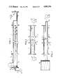
- FIG. 1 is a schematic side view showing a pilot line being pulled through a pipe section to be lined in accordance with the invention
- FIG. 2 is a schematic, side view illustrating a further step in a pipe lining process wherein a heavier gauge pulling line is being pulled through the pipe section to be lined;
- FIG. 3 is a schematic top view illustrating a temporarily deformed pipe liner being pulled through a pipe section in accordance with the invention
- FIG. 4 is a cross-sectional view of a pipe section and associated liner
- FIG. 5 is a cross-sectional view of a temporarily deformed pipe liner in accordance with the invention.
- FIG. 6 is a partial, perspective view illustrating a temporarily deformed liner within a pipe section to be lined
- FIG. 7 is a schematic side view illustrating the commencement of a pipe liner expansion process in accordance with the invention.
- FIG. 8 is a side elevation of a packer/expander assembly for use in the subject invention.
- FIG. 9 is a partial side view of the device illustrated in FIG. 8.
- FIG. 10 is a side schematic view illustrating a fully expanded pipe liner in accordance with the invention.
- FIGS. 11-13 represent a schematic progression illustrating the formation of a radial flange on a pipe liner in accordance with the invention
- FIG. 14 is a top sectional view illustrating a flaring tool in accordance with the subject invention.
- FIG. 15 is a side view of a tool element for use with the flaring tool illustrated in FIG. 14;
- FIGURE 16 is an end view of a pipe lined in accordance with the invention.
- FIG. 17 is a side schematic view illustrating a plurality of aligned pipe sections with individual pipe liners in accordance with the invention.
- FIG. 1 a cylindrical section 10 of pipe to be lined in accordance with this invention is shown in schematic form.
- the pipe is formed with radial flanges 12, 14 at either end to enable connection with adjacent pipe sections in a conventional manner.
- the liner 16 in its final installed form is shown in FIGS. 4, 10, 16 and 17.
- the liner is constructed of HDPE which may be a Union Carbide DGDB-2480 Black 4865 non-cross-linked thermoplastic material meeting the requirements of ASTM 1248-81a for Type PE 34 Class C product. It is characterized by a high level of environmental stress cracking resistance and high strength. Nylon, TeflonTM, ABS or any other such plastic material may also be utilized.
- HDPE which may be a Union Carbide DGDB-2480 Black 4865 non-cross-linked thermoplastic material meeting the requirements of ASTM 1248-81a for Type PE 34 Class C product. It is characterized by a high level of environmental stress cracking resistance and high strength. Nylon, TeflonTM, ABS or any other such plastic material may also be utilized.
- While the pipe lining procedure is shown primarily in schematic form, it will be understood that the pipe may be lined above ground or, in situ underground or underwater. In any or all of the above cases, it may be necessary to disconnect the pipeline at selected, longitudinally spaced access points and, if continuous pipeline flow is required, splice in a bypass section between pipe sections on either side of the section to be lined. This bypassing or splicing procedure forms no part of the present invention and need not be described further.
- the pipe section Before commencing the lining operation, the pipe section should be inspected to determine its ability to withstand pressures applied during the lining operation. Of course, if the pipe is damaged, corroded, etc. to the point of not being able to withstand such pressures, then the pipe section in question must to be replaced rather than lined.
- the interior of the pipe 10 may be cleaned by a conventional brush pig 22 designed to traverse the pipe interior with brushes extending radially into contact with the interior pipe wall, to effect removal of loose material, residue, sediment, and the like which might otherwise negatively impact the lining process.
- a conventional brush pig 22 designed to traverse the pipe interior with brushes extending radially into contact with the interior pipe wall, to effect removal of loose material, residue, sediment, and the like which might otherwise negatively impact the lining process.
- upstream and downstream manifolds 18 and 20 are attached to the pipe flanges 12, 14, respectively.
- the manifolds are provided with abutting flanges 12', 14', and connection is achieved via bolts or other suitable fasteners in conjunction with aligned apertures (FIG. 16) in the respective flanges.
- the upstream manifold 18 has a closed end 30 which comprises a removable plate, and in which is mounted an inlet valve 32.
- the valve 32 is connected via conduit 34 to a pressurIzed air or liquid source 36.
- the downstream manifold 20 is also provided with an end plate which mounts a relief valve 38.
- a pressure gauge 40 monitors pressure within the pipe.
- Pressurized air or water is introduced through a valve 32 into the pipe behind the pig 22, so as to push the brush pig and pulling line 24 through the pipe to the downstream end thereof.
- relief valve 38 is set at about 100 psi to ensure proper degassing of the pipe as the pig moves to the downstream end of the pipe.
- the pig 22 reaches the downstream end, and moves into the manifold 20, the interior pressure of the pipe is gradually released, manifolds 18 and 20 are opened, and pig 22 removed. Thereafter, line 24 may be drawn out and subsequently fastened to an associated winch or reel 44 as shown in FIG. 2.
- the pipe section 10 is shown with manifolds 18 and 20 opened at their remote ends and with an initial lightweight fishing line 24 connected to a heavier gauge pulling or pilot line 42.
- Lines 24 and 42 are pulled through the pipeline 10 by a winch 44 located adjacent the downstream end of the pipeline 10 and manifold 20.
- the pilot line 42 is unwound from a reel 46 at the upstream end of the pipeline section.
- the appropriate gauge pulling line may be cut adjacent the upstream manifold 18 and thereafter attached to the temporarily deformed U-shaped liner 16, as more clearly illustrated in FIG. 3.
- the pulling line 42 is connected to the U-shaped liner 16 by a suitable gripping arrangement shown in schematic form at 50 in FIG. 3.
- the gripping means 50 is of the radial expansion type so as to prevent damage to the end of the liner.
- the U-shaped liner 16 may be unwound from a storage or supply reel 48 which is located adjacent the upstream manifold 18.
- FIG. 4 illustrates a cross-sectional view of pipeline section 10 with the liner 16 in its finally expanded form. This is to contrasted with the cross-sectional view of the pipe liner 16 in FIG. 5 which illustrates it in its temporarily deformed U-shape.
- FIG. 6 a perspective view illustrates the temporarily deformed U-shaped liner 16 after it is pulled through the pipe section 10 to be lined.
- FIG. 7 it will be noted initially that the liner 16 extends approximately to the open ends of the manifolds 18 and 20 to not only facilitate the expansion process, but also to leave sufficient liner to form radial flanges in a manner to be described in greater detail below.
- FIG. 7 there is schematically shown a representation of the initial expansion of the liner 16 within the pipe 10.
- a pair of mechanical expansion/packer assemblies are inserted into the liner from either end of the upstream and downstream manifolds 18, 20.
- the packer/expander assemblies 52, 54 are identical in every respect and, therefore, only one need be described in detail.
- the downstream packer/expander 54 assembly includes an inlet conduit or manifold 56 operatively connected to a closed boiler 58 through which hot liquid may be introduced into the liner via valve 60.
- the temperature of the liquid is monitored by a conventional gauge 62, while the pressure within the liner is monitored by a conventional pressure gauge 64.
- Inlet pipe 56 is connected via pipe extension 56' to a cylindrical packer assembly 66 consisting of conventional packing rings which are sized to seal off the liner relative to the manifold 20 to prevent any escape of liquid from the liner through the manifold.
- a cylindrical wedge-like expander 68 provided with a tapered surface 70, extends forward of the packer assembly and serves to force the liner end back into a cylindrical shape, as best seen in FIG. 7.
- a similar arrangement is provided at the upstream manifold 18 so that the liner 16 is initially expanded mechanically at both ends in the above described manner.
- the expander 68 is provided with an internal bore 72 (FIGS. 8 and 9) which operatively connects to the inlet conduit 56 and closed boiler 58. It will thus be appreciated that expander 68 only initiates the expansion process, while facilitating introduction of hot liquid through the bore 72 and into the liner 16.
- hot water is introduced from the source 58 into the interior of the liner. Because the system is closed, the hot water may be raised to high temperatures without the creation of steam and, in this initial stage, the hot water is introduced into the liner so as to raise the temperature of the liner to approximately its shape memory temperature.
- a relief valve 76 in the packer/expander assembly 52 allows hot water to flow continuously through the liner, at a first pressure of about 7 bars. It will be appreciated that the period of time required to reheat the liner to its shape memory temperature at the first pressure sufficient to return the liner to its cylindrical shape will depend on the diameter and length of the pipe to be lined.
- the U-shaped memory of the liner is erased and the liner tends to assume its original cylindrical shape.
- the now cylindrical liner 16 may not conform exactly to the inner surface of the pipe which may be warped, particularly over extended distances. Accordingly, the pressure inside the liner is raised in a second stage to about 15 bars to expand the liner 16 into substantially exact conformance with the interior surface of the pipe 10, as illustrated in FIG. 10.
- valve 60 is closed, hot water supply 58 disconnected, and the hot water within the pipe is emptied.
- the packer/expander assemblies 52, 54 are then withdrawn.
- a conventional expansion pig having a diameter substantially identical to the inside diameter of the expanded liner, is introduced into the pipe 10 and is pushed through the pipe section applying a radial force to the liner so as to squeeze any remaining air from between the pipe and liner and to thereby conform 100% of the liner surface against the interior surface of the pipe.
- the pig is preferably driven by a supply of cold water which more or less "freezes" the plastic into final form behind the pig, eliminating all air spaces between the liner and the pipe section.
- source 58 may be operatively connected to the upstream assembly 52 as well.
- manifolds 18, 20 and assemblies 52, 54, including conduit 56 are provided with the necessary inlets, outlets for monitoring devices, relief valves, and the like so that, in effect, they are interchangeable.
- FIG. 11 shows the expanded liner 16 extending beyond pipe 10, with the manifold 18 removed.
- the liner will be trimmed in accordance with predetermined and calculated data establishing the length of liner required to produce a given size radial flange for pipes of various diameters.
- a first flaring stage commences wherein the liner end is heated by an air gun for example, to about 180-200° F., and flange 80 is partially formed at an angle of about 50° to about 70° , relative to horizontal, as shown in FIG. 12.
- the specific angle will depend on factors such as the diameter of the pipe, the flange length, and so on.
- FIG. 14 illustrates an exemplary flaring tool for carrying out the first and second flaring stages as described above.
- a manually operated screw jack 82 is fastened at least two locations, preferably 180° apart, about the pipe flange 12.
- a pair of heavy duty bolts 84 extend between bolt holes formed in the flange 12 and a cross bar 86.
- Bar 86 is provided with a threaded aperture 88, intermediate the ends thereof, for receiving a threaded jack member 90 which mounts a flaring tool 92, a packing assembly 94, a washer 96 and a nut 98 on one side of the cross-bar 86, and a handle 100 on the other side of the cross bar.
- FIG. 15 shows in an end view, the liner 16 in its finally flared and expanded configuration within the pipe 10.
- the speed with which the flaring tools are brought into engagement with the liner end or ends must be correlated to the pipe diameter, temperature, etc. to prevent damage to the end or ends.
- the flaring tools do not engage the liner end or ends until the temperature, monitored by conventional means, reaches the predetermined level.
- the tools remain in full pressure engagement with the liner end or ends during the respective cooling steps.
- screw jack 82 may be hydraulically actuated, particularly for larger diameter pipes.
- FIG. 17 there is illustrated a plurality of adjacent pipes 10, each having an individual liner 16 applied in accordance with the above described process.
- the formation of radial flanges 80 on each liner section results in a continuous interior lining with no pipe exposure to the materials flowing through the pipeline.
- This of course is an alternative to introducing a single continuous liner through a plurality of single pipe sections, but with similarly effective results.
Landscapes
- Engineering & Computer Science (AREA)
- Mechanical Engineering (AREA)
- Manufacturing & Machinery (AREA)
- Lining Or Joining Of Plastics Or The Like (AREA)
Abstract
Description
Claims (20)
Priority Applications (16)
| Application Number | Priority Date | Filing Date | Title |
|---|---|---|---|
| US07114949 US4985196B1 (en) | 1987-10-30 | 1987-10-30 | Pipe liner process |
| US07188468 US4986951B1 (en) | 1987-07-27 | 1988-04-29 | Pipe liner process |
| DE19883889992 DE3889992T3 (en) | 1987-07-27 | 1988-06-22 | Method and device for producing a tube lining deformed in cross section. |
| EP19880305688 EP0301697B2 (en) | 1987-07-27 | 1988-06-22 | A method and apparatus for producing a deformed pipe liner of tubular cross-section. |
| ES88305688T ES2054808T5 (en) | 1987-07-27 | 1988-06-22 | A METHOD AND APPARATUS FOR THE PRODUCTION OF A DEFORMED TUBULAR CROSS SECTION TUBE. |
| CA000571626A CA1312716C (en) | 1987-07-27 | 1988-07-08 | Pipe liner process and apparatus |
| AU18938/88A AU610196B2 (en) | 1987-07-27 | 1988-07-11 | Improved pipe liner process and apparatus |
| EG39188A EG18534A (en) | 1987-07-27 | 1988-07-17 | Improved pipe liner process and apparatus |
| SU4356295 RU2039314C1 (en) | 1987-07-27 | 1988-07-26 | Method and device for making deformed pipe lining |
| CN 88104555 CN1016407B (en) | 1987-07-27 | 1988-07-26 | Method and apparatus deforming reformable tubular pipe liners |
| BR8803717A BR8803717A (en) | 1987-07-27 | 1988-07-26 | PROCESS AND APPLIANCE TO PRODUCE A DEFORMED TUBE LINING, PROCESS TO INSTALL A HOLE CYLINDRICAL THERMOPLASTIC LINING IN A TUBE AND APPLIANCE TO INSTALL A PARTIALLY FLEXED LINING INSIDE A TUBE |
| JP63187953A JP2728266B2 (en) | 1987-07-27 | 1988-07-27 | How to attach a pipe liner |
| CH28489A CH679845A5 (en) | 1987-07-27 | 1989-01-27 | |
| US07/626,536 US5112211A (en) | 1987-10-30 | 1990-12-12 | Pipe lining apparatus |
| SG136394A SG136394G (en) | 1987-07-27 | 1994-09-23 | A method and apparatus for producing deformed pipe liner of tubular cross-section |
| HK19695A HK19695A (en) | 1987-07-27 | 1995-02-16 | A method and apparatus for producing a deformed pipe liner of tubular cross-section |
Applications Claiming Priority (1)
| Application Number | Priority Date | Filing Date | Title |
|---|---|---|---|
| US07114949 US4985196B1 (en) | 1987-10-30 | 1987-10-30 | Pipe liner process |
Related Child Applications (2)
| Application Number | Title | Priority Date | Filing Date |
|---|---|---|---|
| US07188468 Continuation-In-Part US4986951B1 (en) | 1987-07-27 | 1988-04-29 | Pipe liner process |
| US07/626,536 Division US5112211A (en) | 1987-10-30 | 1990-12-12 | Pipe lining apparatus |
Publications (2)
| Publication Number | Publication Date |
|---|---|
| US4985196A true US4985196A (en) | 1991-01-15 |
| US4985196B1 US4985196B1 (en) | 1997-11-18 |
Family
ID=22358426
Family Applications (1)
| Application Number | Title | Priority Date | Filing Date |
|---|---|---|---|
| US07114949 Expired - Lifetime US4985196B1 (en) | 1987-07-27 | 1987-10-30 | Pipe liner process |
Country Status (1)
| Country | Link |
|---|---|
| US (1) | US4985196B1 (en) |
Cited By (55)
| Publication number | Priority date | Publication date | Assignee | Title |
|---|---|---|---|---|
| US5112211A (en) * | 1987-10-30 | 1992-05-12 | Pipe Liners, Inc. | Pipe lining apparatus |
| US5213727A (en) * | 1991-06-03 | 1993-05-25 | American Pipe & Plastics, Inc. | Method for installing a pipe liner |
| US5223189A (en) * | 1992-01-07 | 1993-06-29 | Gundle Lining Systems, Inc. | Method of sealing lateral connections for pipe liners |
| US5244624A (en) * | 1986-03-31 | 1993-09-14 | Nupipe, Inc. | Method of installing a new pipe inside an existing conduit by progressive rounding |
| US5318421A (en) * | 1991-05-17 | 1994-06-07 | Subterra Limited | Apparatus for producing a deformed pipe |
| US5368809A (en) * | 1986-03-31 | 1994-11-29 | Nupipe, Inc. | Method of installing a new pipe inside an existing conduit by progressive rounding |
| US5395472A (en) * | 1992-08-20 | 1995-03-07 | Mandich; Ivan C. | Lining system and methods for installing plastic liners in a pipe |
| AU658183B2 (en) * | 1991-06-03 | 1995-04-06 | American Pipe & Plastics, Inc. | Method and apparatus for installing a pipe liner |
| US5447664A (en) * | 1992-10-14 | 1995-09-05 | Tokyo Gas Co., Ltd. | Method of lining an inner surface of a pipe |
| US5501248A (en) * | 1994-06-23 | 1996-03-26 | Lmk Enterprises, Inc. | Expandable pipe liner and method of installing same |
| US5609186A (en) * | 1994-11-14 | 1997-03-11 | Tokyo Gas Co., Ltd. | Methods of lining the internal surface of a pipe |
| US5632952A (en) * | 1994-12-09 | 1997-05-27 | Mandich; Ivan C. | Method for lining lateral and main pipes |
| US5653555A (en) | 1995-05-19 | 1997-08-05 | Inliner, U.S.A. | Multiple resin system for rehabilitating pipe |
| US5671778A (en) * | 1993-05-24 | 1997-09-30 | Ashimori Kogyo Kabushiki Kaisha | Repairing tube, method for repairing pipe lines therewith and method for removing the repairing tube |
| US5676175A (en) * | 1995-06-26 | 1997-10-14 | Golan Plastic Products | Plastic liner |
| US5699838A (en) | 1995-05-22 | 1997-12-23 | Inliner, U.S.A. | Apparatus for vacuum impregnation of a flexible, hollow tube |
| US5816293A (en) * | 1996-03-27 | 1998-10-06 | Kiest, Jr.; Larry W. | Apparatus for installation of a liner within a pipeline |
| US5855729A (en) * | 1994-08-19 | 1999-01-05 | Lmk Enterprises | Apparatus for providing a tubular material within a pipeline |
| US5861116A (en) * | 1994-08-31 | 1999-01-19 | Plastic Innovations, Inc. | Process for installing a pipe liner |
| US5950682A (en) * | 1994-08-19 | 1999-09-14 | Lmk Enterprises, Inc. | Apparatus and method for repairing the junction of a sewer main line and lateral |
| EP0943417A1 (en) * | 1997-10-09 | 1999-09-22 | Tokyo Gas Co., Ltd. | Method of lining inner surface of conduit |
| US5964249A (en) * | 1996-03-27 | 1999-10-12 | Lmk Enterprises, Inc. | Apparatus and method for repairing a pipeline |
| US5992467A (en) * | 1996-12-30 | 1999-11-30 | Roach; Max Jerry | Liner reduction system using pressurized dies and apparatus therefor |
| US6019136A (en) * | 1997-12-04 | 2000-02-01 | Fiberglass Coatings, Inc. | Conduit repair system |
| WO2000006338A1 (en) * | 1998-07-29 | 2000-02-10 | Safetyliner Systems, Llc | Insertion of liners into host tubulars by fluid injection |
| US6058978A (en) * | 1994-03-11 | 2000-05-09 | Paletta; Stephen | Polymeric pipe deformer and method for relining existing pipelines |
| US6299803B1 (en) | 1999-10-21 | 2001-10-09 | Ledoux Patrick | Method for forming and sealing pipe liners |
| US6423258B1 (en) | 2000-07-31 | 2002-07-23 | American Pipe & Plastics, Inc. | Machine and method for providing folded pipe liners |
| US20030038403A1 (en) * | 2001-08-21 | 2003-02-27 | American Pipe & Plastics, Inc. | Machine and method for providing folded pipe liners |
| US6539978B1 (en) * | 1998-06-10 | 2003-04-01 | Lattice Intellectual Property Ltd | Pipe lining |
| US20030077125A1 (en) * | 2001-10-19 | 2003-04-24 | Heerema Marine Contractors Nederland B.V. | Methods of fitting linings in pipelines |
| KR100388437B1 (en) * | 2000-08-24 | 2003-06-25 | 이완영 | Maunfacturing Process Of Plastic Lined Pipe |
| US20030212510A1 (en) * | 2002-05-13 | 2003-11-13 | Gee Gregory P. | Optimized convection based mass airflow sensor circuit |
| US6723266B1 (en) | 2002-11-18 | 2004-04-20 | Raymond Lippiatt | Lining of underground pipes |
| US20040202888A1 (en) * | 2003-04-08 | 2004-10-14 | Yang-Tse Cheng | Self-healing tribological surfaces |
| US20050161100A1 (en) * | 2002-06-19 | 2005-07-28 | Robert Pleydon | Inversion liner and liner components for conduits |
| US7037043B1 (en) | 2005-02-14 | 2006-05-02 | Pipe Liners, Inc. | Methods for lining pipes and connecting the lined pipe with adjacent or lateral pipes |
| US20060124188A1 (en) * | 2004-12-13 | 2006-06-15 | Catha Stephen C | Pipe liner apparatus and method |
| WO2006064284A1 (en) | 2004-12-13 | 2006-06-22 | Smart Pipe Company, Lp | Systems and methods for making pipe liners |
| KR100606188B1 (en) * | 2006-04-28 | 2006-07-31 | 동도기공 주식회사 | Polyethylene pi p e rehabilitation |
| US7104574B2 (en) | 2000-01-20 | 2006-09-12 | Uponor Eti Company | Corrugated pipe connection joint |
| US20070018455A1 (en) * | 2005-07-21 | 2007-01-25 | Pipe Liners, Inc. | Apparatus and methods for fusing non-cylindrical thermoplastic pipe ends |
| EP1747447A2 (en) * | 2004-05-07 | 2007-01-31 | David E. Kranbuehl | Method to predict the end-point, replacement time and to monitor changes in that time by using pre aged witness coupons |
| WO2008024800A2 (en) * | 2006-08-21 | 2008-02-28 | Western Slope Utilities, Inc. | Systems and methods for swab transport in pipeline rehabilitation |
| US20090205733A1 (en) * | 2007-12-26 | 2009-08-20 | Stringfellow William D | Methods and systems for in situ pipe lining |
| US20090308475A1 (en) * | 2005-01-12 | 2009-12-17 | Stringfellow William D | Methods and systems for in situ manufacture and installation of non-metallic high pressure pipe and pipe liners |
| US7861743B1 (en) * | 2007-03-16 | 2011-01-04 | Wren Joseph J | Sacrificial conduit lining system |
| WO2011070353A2 (en) | 2009-12-07 | 2011-06-16 | Smart Pipe Company, Lp | Systems and methods for making pipe, and method of installing the pipe in a pipeline |
| US20120285575A1 (en) * | 2007-12-26 | 2012-11-15 | Stephen Croockett Catha | Movable factory for simultaneous mobile field manufacturing and installation of non-metallic pipe |
| WO2013167889A2 (en) | 2012-05-08 | 2013-11-14 | Smart Pipe Company Inc. | Movable factory for simultaneous mobile field manufacturing and installation of non-metallic pipe |
| US9163771B1 (en) | 2015-01-26 | 2015-10-20 | Rosetta Higman | Conduit repair system |
| US9267635B2 (en) | 2013-03-11 | 2016-02-23 | Exxonmobil Upstream Research Company | Pipeline liner monitoring system |
| US9273801B1 (en) | 2013-01-02 | 2016-03-01 | Joseph Timothy Nippes | Method of in-situ pipeline replacement |
| US9435480B2 (en) | 2015-01-26 | 2016-09-06 | Rosetta Higman | Conduit repair system |
| US9581279B1 (en) | 2015-11-23 | 2017-02-28 | William G. Higman | Multi-layered conduit repair system |
Citations (60)
| Publication number | Priority date | Publication date | Assignee | Title |
|---|---|---|---|---|
| US677142A (en) * | 1898-05-03 | 1901-06-25 | Sam Thomas Richardson | Apparatus for bending into circular form metallic wheel-rims. |
| GB275964A (en) * | 1926-08-14 | 1928-03-08 | Josef Meiser | Process for re-modelling tubes |
| US2423260A (en) * | 1944-12-29 | 1947-07-01 | Extruded Plasties Inc | Extrusion of tubing |
| US2668987A (en) * | 1950-10-21 | 1954-02-16 | Gen Motors Corp | Mold for and method of molding foam rubber strips and the like |
| US2724672A (en) * | 1951-11-29 | 1955-11-22 | Kellogg M W Co | Method of applying thermoplastic polymers to solid surfaces |
| GB807413A (en) * | 1955-06-27 | 1959-01-14 | Tubovit Societa Per Azioni | Improved process for applying a thermoplastic inner lining to pipes made of non-thermoplastic material |
| US2955318A (en) * | 1958-05-16 | 1960-10-11 | Union Carbide Corp | Method and apparatus for collapsing thermoplastic tubing |
| US2971225A (en) * | 1958-09-18 | 1961-02-14 | Bauer Bros Co | Method of lining metal articles |
| US2980161A (en) * | 1954-12-27 | 1961-04-18 | Frank A Howard | Continuous mechanized production of tubeless tire safety rings |
| US3192612A (en) * | 1963-04-05 | 1965-07-06 | Phillips Petroleum Co | Method of constructing plastic-lined conduit |
| US3335758A (en) * | 1964-09-22 | 1967-08-15 | Tfe Company | Plastic-lined conduit |
| US3371770A (en) * | 1966-10-25 | 1968-03-05 | American Pipe & Constr Co | Apparatus for moving pipe through a coating machine |
| US3429954A (en) * | 1965-03-22 | 1969-02-25 | Dow Chemical Co | Method of making a polymer-lined pipe |
| US3543334A (en) * | 1967-05-09 | 1970-12-01 | Mitsubishi Petrochemical Co | Apparatus for manufacturing thermoplastic films |
| CH536703A (en) * | 1972-08-24 | 1973-05-15 | Symalit Ag | Double walled plastics gutter - made from pipe by deforming into u shape |
| US3755524A (en) * | 1970-10-26 | 1973-08-28 | Climate Conditioning Corp | Method for making pipe reducers |
| US3758361A (en) * | 1970-11-16 | 1973-09-11 | J Hunter | Process for lining pipe joints |
| GB1340068A (en) * | 1970-09-22 | 1973-12-05 | Insituform Pipes & Structures | Lining of surfaces defining passageways |
| GB1352829A (en) * | 1969-12-23 | 1974-05-15 | Ross L A R | Internal lining and sealing of hollow ducts |
| US3856905A (en) * | 1972-09-22 | 1974-12-24 | Dow Chemical Co | Oriented plastic tube |
| US3897530A (en) * | 1972-10-27 | 1975-07-29 | Dow Chemical Co | Method for gusseting continuous lengths of tubular material |
| US3959424A (en) * | 1973-12-07 | 1976-05-25 | The Dow Chemical Company | Method for the preparation of plastic lined pipe |
| GB1437273A (en) * | 1972-09-07 | 1976-05-26 | Stabilator Ab | Method of lining pipes |
| US3996967A (en) * | 1972-10-18 | 1976-12-14 | Takata Kojyo Co., Ltd. | Reinforced lining for tubes |
| US4020136A (en) * | 1969-04-12 | 1977-04-26 | Giosue Zaro | Method and apparatus for the sizing of tubular bodies of a thermoplastic material which are continuously extruded |
| US4028037A (en) * | 1975-03-17 | 1977-06-07 | The Dow Chemical Company | Tube treating and apparatus therefor |
| GB2003576A (en) * | 1977-07-27 | 1979-03-14 | Trio Engineering Ltd As | Lining passageways |
| GB1553408A (en) * | 1975-07-02 | 1979-09-26 | Norske Remfabrik As | Lining tube for and method of lining a pipeline |
| GB2018384A (en) * | 1978-04-05 | 1979-10-17 | Cahuzac D | Sheath for forming an internal lining for a conduit and a process for using the sheath |
| US4207130A (en) * | 1977-07-27 | 1980-06-10 | Trio Engineering Limited | Lining of passageways |
| CA1084224A (en) * | 1979-08-21 | 1980-08-26 | Perry N. Brittain | Process for lining high pressure pipeline |
| US4233101A (en) * | 1976-12-09 | 1980-11-11 | Frederick Scragg | Method of lining a pipe |
| GB1580438A (en) * | 1976-07-28 | 1980-12-03 | Trio Eng Inc | Lining of pipelins and passgeways |
| US4273605A (en) * | 1974-01-21 | 1981-06-16 | Ross Louis A R | Internal lining and sealing of hollow ducts |
| FR2487702A1 (en) * | 1980-07-31 | 1982-02-05 | Perinelle Robert | Derivation of non standard tube from standard lengths - involves deforming standard tube between rollers or using press with or without internal former |
| GB2080917A (en) * | 1980-07-09 | 1982-02-10 | Nakashin Yasushi | Repairing underground pipes |
| US4321740A (en) * | 1980-05-13 | 1982-03-30 | Inner-Tite Corporation | Methods and apparatus for relining service pipe |
| GB2084686A (en) * | 1980-09-25 | 1982-04-15 | British Steel Corp | Lining pipework |
| GB2094862A (en) * | 1981-03-14 | 1982-09-22 | Dunlop Ltd | Lining of tubular structures |
| FR2503622A1 (en) * | 1981-04-13 | 1982-10-15 | Laurent Jacques | PROCESS FOR INTERIORALLY PUTTING PIPES AND TUBE FOR ITS IMPLEMENTATION |
| US4361451A (en) * | 1980-04-18 | 1982-11-30 | Coopetanche S.A. | Process for everting a lining into a conduit utilizing two injection fluids |
| US4368091A (en) * | 1978-12-29 | 1983-01-11 | Tokyo Gas Co. Ltd. | Method for providing the inner surface of a pipe with a flexible tubular lining material through a liquid resin under pressure |
| US4377894A (en) * | 1980-03-21 | 1983-03-29 | Kawasaki Jukogyo Kabushiki Kaisha | Method of lining inner wall surfaces of hollow articles |
| US4394202A (en) * | 1981-01-22 | 1983-07-19 | Umac, Inc. | Method for relining an underground gas line or the like without excavation |
| US4410391A (en) * | 1981-01-22 | 1983-10-18 | Umac, Inc. | Apparatus for relining an underground gas line or the like without excavation |
| EP0098547A1 (en) * | 1982-07-02 | 1984-01-18 | Trio Engineering Limited | Improvements relating to the lining of passageways |
| US4427480A (en) * | 1980-08-19 | 1984-01-24 | Tokyo Gas Co. Ltd. | Method and apparatus for providing the inner surface of a pipe line with a tubular lining material |
| US4446891A (en) * | 1980-11-04 | 1984-05-08 | Gebelius Sven Runo Vilhelm | Method for repairing and/or reinforcing a pipe system, and a device for utilization of the method |
| US4483167A (en) * | 1981-07-14 | 1984-11-20 | Kabushiki Kaisha Sanyo Seiki | Forming rolls for use in the fabrication of welded tubes |
| US4496499A (en) * | 1980-01-25 | 1985-01-29 | Brittain Perry N | Process for lining high pressure pipeline |
| US4504171A (en) * | 1983-09-02 | 1985-03-12 | Getty Synthetic Fuels, Inc. | Liner installation tool and method |
| US4560295A (en) * | 1982-06-17 | 1985-12-24 | Alps Electric Co. Ltd. | Sheet presser mechanism for recorders with pivotable cover plate |
| US4627471A (en) * | 1983-05-23 | 1986-12-09 | British Gas Corporation | Sealing joints and leaks |
| US4650703A (en) * | 1984-04-26 | 1987-03-17 | Raychem Gmbh | Recoverable article and method |
| GB2184194A (en) * | 1985-12-13 | 1987-06-17 | Bio Kil Chemicals Ltd | Method for applying a protective coating |
| WO1987003840A1 (en) * | 1985-12-20 | 1987-07-02 | Roy Binall Skott | Method and means for applying flexible liners to pipes |
| GB2186340A (en) * | 1986-02-10 | 1987-08-12 | British Gas Plc | Pipe lining and closure therefor |
| US4691740A (en) * | 1983-03-15 | 1987-09-08 | Phillips Petroleum Company | Pipeline lining |
| GB2188695A (en) * | 1986-03-31 | 1987-10-07 | Jr Campbell Hall Steketee | Lining pipes |
| WO1988004987A1 (en) * | 1986-12-26 | 1988-07-14 | Osaka Gas Company Limited | Duct lining method |
-
1987
- 1987-10-30 US US07114949 patent/US4985196B1/en not_active Expired - Lifetime
Patent Citations (62)
| Publication number | Priority date | Publication date | Assignee | Title |
|---|---|---|---|---|
| US677142A (en) * | 1898-05-03 | 1901-06-25 | Sam Thomas Richardson | Apparatus for bending into circular form metallic wheel-rims. |
| GB275964A (en) * | 1926-08-14 | 1928-03-08 | Josef Meiser | Process for re-modelling tubes |
| US2423260A (en) * | 1944-12-29 | 1947-07-01 | Extruded Plasties Inc | Extrusion of tubing |
| US2668987A (en) * | 1950-10-21 | 1954-02-16 | Gen Motors Corp | Mold for and method of molding foam rubber strips and the like |
| US2724672A (en) * | 1951-11-29 | 1955-11-22 | Kellogg M W Co | Method of applying thermoplastic polymers to solid surfaces |
| US2980161A (en) * | 1954-12-27 | 1961-04-18 | Frank A Howard | Continuous mechanized production of tubeless tire safety rings |
| GB807413A (en) * | 1955-06-27 | 1959-01-14 | Tubovit Societa Per Azioni | Improved process for applying a thermoplastic inner lining to pipes made of non-thermoplastic material |
| US2955318A (en) * | 1958-05-16 | 1960-10-11 | Union Carbide Corp | Method and apparatus for collapsing thermoplastic tubing |
| US2971225A (en) * | 1958-09-18 | 1961-02-14 | Bauer Bros Co | Method of lining metal articles |
| US3192612A (en) * | 1963-04-05 | 1965-07-06 | Phillips Petroleum Co | Method of constructing plastic-lined conduit |
| US3335758A (en) * | 1964-09-22 | 1967-08-15 | Tfe Company | Plastic-lined conduit |
| US3429954A (en) * | 1965-03-22 | 1969-02-25 | Dow Chemical Co | Method of making a polymer-lined pipe |
| US3371770A (en) * | 1966-10-25 | 1968-03-05 | American Pipe & Constr Co | Apparatus for moving pipe through a coating machine |
| US3543334A (en) * | 1967-05-09 | 1970-12-01 | Mitsubishi Petrochemical Co | Apparatus for manufacturing thermoplastic films |
| US4020136A (en) * | 1969-04-12 | 1977-04-26 | Giosue Zaro | Method and apparatus for the sizing of tubular bodies of a thermoplastic material which are continuously extruded |
| GB1352829A (en) * | 1969-12-23 | 1974-05-15 | Ross L A R | Internal lining and sealing of hollow ducts |
| GB1340068A (en) * | 1970-09-22 | 1973-12-05 | Insituform Pipes & Structures | Lining of surfaces defining passageways |
| US3755524A (en) * | 1970-10-26 | 1973-08-28 | Climate Conditioning Corp | Method for making pipe reducers |
| US3758361A (en) * | 1970-11-16 | 1973-09-11 | J Hunter | Process for lining pipe joints |
| CH536703A (en) * | 1972-08-24 | 1973-05-15 | Symalit Ag | Double walled plastics gutter - made from pipe by deforming into u shape |
| GB1437273A (en) * | 1972-09-07 | 1976-05-26 | Stabilator Ab | Method of lining pipes |
| US3856905A (en) * | 1972-09-22 | 1974-12-24 | Dow Chemical Co | Oriented plastic tube |
| US3996967A (en) * | 1972-10-18 | 1976-12-14 | Takata Kojyo Co., Ltd. | Reinforced lining for tubes |
| US3897530A (en) * | 1972-10-27 | 1975-07-29 | Dow Chemical Co | Method for gusseting continuous lengths of tubular material |
| US3959424A (en) * | 1973-12-07 | 1976-05-25 | The Dow Chemical Company | Method for the preparation of plastic lined pipe |
| US4273605A (en) * | 1974-01-21 | 1981-06-16 | Ross Louis A R | Internal lining and sealing of hollow ducts |
| US4028037A (en) * | 1975-03-17 | 1977-06-07 | The Dow Chemical Company | Tube treating and apparatus therefor |
| GB1553408A (en) * | 1975-07-02 | 1979-09-26 | Norske Remfabrik As | Lining tube for and method of lining a pipeline |
| GB1580438A (en) * | 1976-07-28 | 1980-12-03 | Trio Eng Inc | Lining of pipelins and passgeways |
| US4233101A (en) * | 1976-12-09 | 1980-11-11 | Frederick Scragg | Method of lining a pipe |
| US4207130A (en) * | 1977-07-27 | 1980-06-10 | Trio Engineering Limited | Lining of passageways |
| GB2003576A (en) * | 1977-07-27 | 1979-03-14 | Trio Engineering Ltd As | Lining passageways |
| GB2018384A (en) * | 1978-04-05 | 1979-10-17 | Cahuzac D | Sheath for forming an internal lining for a conduit and a process for using the sheath |
| US4368091A (en) * | 1978-12-29 | 1983-01-11 | Tokyo Gas Co. Ltd. | Method for providing the inner surface of a pipe with a flexible tubular lining material through a liquid resin under pressure |
| CA1084224A (en) * | 1979-08-21 | 1980-08-26 | Perry N. Brittain | Process for lining high pressure pipeline |
| US4496499A (en) * | 1980-01-25 | 1985-01-29 | Brittain Perry N | Process for lining high pressure pipeline |
| US4377894A (en) * | 1980-03-21 | 1983-03-29 | Kawasaki Jukogyo Kabushiki Kaisha | Method of lining inner wall surfaces of hollow articles |
| US4361451A (en) * | 1980-04-18 | 1982-11-30 | Coopetanche S.A. | Process for everting a lining into a conduit utilizing two injection fluids |
| US4321740A (en) * | 1980-05-13 | 1982-03-30 | Inner-Tite Corporation | Methods and apparatus for relining service pipe |
| GB2080917A (en) * | 1980-07-09 | 1982-02-10 | Nakashin Yasushi | Repairing underground pipes |
| FR2487702A1 (en) * | 1980-07-31 | 1982-02-05 | Perinelle Robert | Derivation of non standard tube from standard lengths - involves deforming standard tube between rollers or using press with or without internal former |
| US4427480A (en) * | 1980-08-19 | 1984-01-24 | Tokyo Gas Co. Ltd. | Method and apparatus for providing the inner surface of a pipe line with a tubular lining material |
| GB2084686A (en) * | 1980-09-25 | 1982-04-15 | British Steel Corp | Lining pipework |
| US4446891A (en) * | 1980-11-04 | 1984-05-08 | Gebelius Sven Runo Vilhelm | Method for repairing and/or reinforcing a pipe system, and a device for utilization of the method |
| US4394202A (en) * | 1981-01-22 | 1983-07-19 | Umac, Inc. | Method for relining an underground gas line or the like without excavation |
| US4410391A (en) * | 1981-01-22 | 1983-10-18 | Umac, Inc. | Apparatus for relining an underground gas line or the like without excavation |
| GB2094862A (en) * | 1981-03-14 | 1982-09-22 | Dunlop Ltd | Lining of tubular structures |
| EP0065886A1 (en) * | 1981-04-13 | 1982-12-01 | Jacques Laurent | Method of lining a passageway and tube for carrying it out |
| FR2503622A1 (en) * | 1981-04-13 | 1982-10-15 | Laurent Jacques | PROCESS FOR INTERIORALLY PUTTING PIPES AND TUBE FOR ITS IMPLEMENTATION |
| US4483167A (en) * | 1981-07-14 | 1984-11-20 | Kabushiki Kaisha Sanyo Seiki | Forming rolls for use in the fabrication of welded tubes |
| US4560295A (en) * | 1982-06-17 | 1985-12-24 | Alps Electric Co. Ltd. | Sheet presser mechanism for recorders with pivotable cover plate |
| EP0098547A1 (en) * | 1982-07-02 | 1984-01-18 | Trio Engineering Limited | Improvements relating to the lining of passageways |
| US4691740A (en) * | 1983-03-15 | 1987-09-08 | Phillips Petroleum Company | Pipeline lining |
| US4627471A (en) * | 1983-05-23 | 1986-12-09 | British Gas Corporation | Sealing joints and leaks |
| US4643855A (en) * | 1983-05-23 | 1987-02-17 | British Gas Corporation | Sealing joints and leaks |
| US4504171A (en) * | 1983-09-02 | 1985-03-12 | Getty Synthetic Fuels, Inc. | Liner installation tool and method |
| US4650703A (en) * | 1984-04-26 | 1987-03-17 | Raychem Gmbh | Recoverable article and method |
| GB2184194A (en) * | 1985-12-13 | 1987-06-17 | Bio Kil Chemicals Ltd | Method for applying a protective coating |
| WO1987003840A1 (en) * | 1985-12-20 | 1987-07-02 | Roy Binall Skott | Method and means for applying flexible liners to pipes |
| GB2186340A (en) * | 1986-02-10 | 1987-08-12 | British Gas Plc | Pipe lining and closure therefor |
| GB2188695A (en) * | 1986-03-31 | 1987-10-07 | Jr Campbell Hall Steketee | Lining pipes |
| WO1988004987A1 (en) * | 1986-12-26 | 1988-07-14 | Osaka Gas Company Limited | Duct lining method |
Cited By (75)
| Publication number | Priority date | Publication date | Assignee | Title |
|---|---|---|---|---|
| US5397513A (en) * | 1986-03-31 | 1995-03-14 | Nupipe, Inc. | Method for installing a length of substantially rigid thermoplastic pipe in an existing conduit |
| US5368809A (en) * | 1986-03-31 | 1994-11-29 | Nupipe, Inc. | Method of installing a new pipe inside an existing conduit by progressive rounding |
| US5244624A (en) * | 1986-03-31 | 1993-09-14 | Nupipe, Inc. | Method of installing a new pipe inside an existing conduit by progressive rounding |
| US5112211A (en) * | 1987-10-30 | 1992-05-12 | Pipe Liners, Inc. | Pipe lining apparatus |
| US5318421A (en) * | 1991-05-17 | 1994-06-07 | Subterra Limited | Apparatus for producing a deformed pipe |
| US5273414A (en) * | 1991-06-03 | 1993-12-28 | American Pipe & Plastics, Inc. | Method and apparatus for installing a pipe liner |
| US5213727A (en) * | 1991-06-03 | 1993-05-25 | American Pipe & Plastics, Inc. | Method for installing a pipe liner |
| AU658183B2 (en) * | 1991-06-03 | 1995-04-06 | American Pipe & Plastics, Inc. | Method and apparatus for installing a pipe liner |
| US5223189A (en) * | 1992-01-07 | 1993-06-29 | Gundle Lining Systems, Inc. | Method of sealing lateral connections for pipe liners |
| US5395472A (en) * | 1992-08-20 | 1995-03-07 | Mandich; Ivan C. | Lining system and methods for installing plastic liners in a pipe |
| US5447664A (en) * | 1992-10-14 | 1995-09-05 | Tokyo Gas Co., Ltd. | Method of lining an inner surface of a pipe |
| US5671778A (en) * | 1993-05-24 | 1997-09-30 | Ashimori Kogyo Kabushiki Kaisha | Repairing tube, method for repairing pipe lines therewith and method for removing the repairing tube |
| US6058978A (en) * | 1994-03-11 | 2000-05-09 | Paletta; Stephen | Polymeric pipe deformer and method for relining existing pipelines |
| US5501248A (en) * | 1994-06-23 | 1996-03-26 | Lmk Enterprises, Inc. | Expandable pipe liner and method of installing same |
| US5950682A (en) * | 1994-08-19 | 1999-09-14 | Lmk Enterprises, Inc. | Apparatus and method for repairing the junction of a sewer main line and lateral |
| US5855729A (en) * | 1994-08-19 | 1999-01-05 | Lmk Enterprises | Apparatus for providing a tubular material within a pipeline |
| US5861116A (en) * | 1994-08-31 | 1999-01-19 | Plastic Innovations, Inc. | Process for installing a pipe liner |
| US5740838A (en) * | 1994-11-14 | 1998-04-21 | Tokyo Gas Co., Ltd. | Methods of lining the internal surface of a pipe |
| US5873390A (en) * | 1994-11-14 | 1999-02-23 | Tokyo Gas Co., Ltd. | Methods of lining the internal surface of a pipe |
| US5609186A (en) * | 1994-11-14 | 1997-03-11 | Tokyo Gas Co., Ltd. | Methods of lining the internal surface of a pipe |
| US5632952A (en) * | 1994-12-09 | 1997-05-27 | Mandich; Ivan C. | Method for lining lateral and main pipes |
| US5653555A (en) | 1995-05-19 | 1997-08-05 | Inliner, U.S.A. | Multiple resin system for rehabilitating pipe |
| US5699838A (en) | 1995-05-22 | 1997-12-23 | Inliner, U.S.A. | Apparatus for vacuum impregnation of a flexible, hollow tube |
| US5676175A (en) * | 1995-06-26 | 1997-10-14 | Golan Plastic Products | Plastic liner |
| US5816293A (en) * | 1996-03-27 | 1998-10-06 | Kiest, Jr.; Larry W. | Apparatus for installation of a liner within a pipeline |
| US5964249A (en) * | 1996-03-27 | 1999-10-12 | Lmk Enterprises, Inc. | Apparatus and method for repairing a pipeline |
| US5992467A (en) * | 1996-12-30 | 1999-11-30 | Roach; Max Jerry | Liner reduction system using pressurized dies and apparatus therefor |
| EP0943417A1 (en) * | 1997-10-09 | 1999-09-22 | Tokyo Gas Co., Ltd. | Method of lining inner surface of conduit |
| EP0943417A4 (en) * | 1997-10-09 | 2002-03-06 | Tokyo Gas Co Ltd | Method of lining inner surface of conduit |
| US6019136A (en) * | 1997-12-04 | 2000-02-01 | Fiberglass Coatings, Inc. | Conduit repair system |
| US6539978B1 (en) * | 1998-06-10 | 2003-04-01 | Lattice Intellectual Property Ltd | Pipe lining |
| WO2000006338A1 (en) * | 1998-07-29 | 2000-02-10 | Safetyliner Systems, Llc | Insertion of liners into host tubulars by fluid injection |
| US6523574B1 (en) | 1998-07-29 | 2003-02-25 | Safetyliner Systems, Llc | Insertion of liners into host tubulars by fluid injection |
| US6299803B1 (en) | 1999-10-21 | 2001-10-09 | Ledoux Patrick | Method for forming and sealing pipe liners |
| US7104574B2 (en) | 2000-01-20 | 2006-09-12 | Uponor Eti Company | Corrugated pipe connection joint |
| US6423258B1 (en) | 2000-07-31 | 2002-07-23 | American Pipe & Plastics, Inc. | Machine and method for providing folded pipe liners |
| KR100388437B1 (en) * | 2000-08-24 | 2003-06-25 | 이완영 | Maunfacturing Process Of Plastic Lined Pipe |
| US20030038403A1 (en) * | 2001-08-21 | 2003-02-27 | American Pipe & Plastics, Inc. | Machine and method for providing folded pipe liners |
| US20030077125A1 (en) * | 2001-10-19 | 2003-04-24 | Heerema Marine Contractors Nederland B.V. | Methods of fitting linings in pipelines |
| US20030212510A1 (en) * | 2002-05-13 | 2003-11-13 | Gee Gregory P. | Optimized convection based mass airflow sensor circuit |
| US20050161100A1 (en) * | 2002-06-19 | 2005-07-28 | Robert Pleydon | Inversion liner and liner components for conduits |
| US6723266B1 (en) | 2002-11-18 | 2004-04-20 | Raymond Lippiatt | Lining of underground pipes |
| US20040202888A1 (en) * | 2003-04-08 | 2004-10-14 | Yang-Tse Cheng | Self-healing tribological surfaces |
| US7060140B2 (en) * | 2003-04-08 | 2006-06-13 | General Motors Corporation | Self-healing tribological surfaces |
| EP1747447A4 (en) * | 2004-05-07 | 2011-02-09 | David E Kranbuehl | Method to predict the end-point, replacement time and to monitor changes in that time by using pre aged witness coupons |
| EP1747447A2 (en) * | 2004-05-07 | 2007-01-31 | David E. Kranbuehl | Method to predict the end-point, replacement time and to monitor changes in that time by using pre aged witness coupons |
| WO2006064284A1 (en) | 2004-12-13 | 2006-06-22 | Smart Pipe Company, Lp | Systems and methods for making pipe liners |
| US7258141B2 (en) * | 2004-12-13 | 2007-08-21 | Catha Stephen C | Pipe liner apparatus and method |
| US20060124188A1 (en) * | 2004-12-13 | 2006-06-15 | Catha Stephen C | Pipe liner apparatus and method |
| US20090308475A1 (en) * | 2005-01-12 | 2009-12-17 | Stringfellow William D | Methods and systems for in situ manufacture and installation of non-metallic high pressure pipe and pipe liners |
| US8567450B2 (en) * | 2005-01-12 | 2013-10-29 | Smart Pipe Company Lp | Methods and systems for in situ manufacture and installation of non-metallic high pressure pipe and pipe liners |
| US20060182500A1 (en) * | 2005-02-14 | 2006-08-17 | Pipe Liners, Inc. | Methods for aligning pipes and connecting the lined pipe with adjacent or lateral pipes |
| US7172369B2 (en) | 2005-02-14 | 2007-02-06 | Pipe Liners, Inc. | Methods for aligning pipes and connecting the lined pipe with adjacent or lateral pipes |
| US7037043B1 (en) | 2005-02-14 | 2006-05-02 | Pipe Liners, Inc. | Methods for lining pipes and connecting the lined pipe with adjacent or lateral pipes |
| US20070018455A1 (en) * | 2005-07-21 | 2007-01-25 | Pipe Liners, Inc. | Apparatus and methods for fusing non-cylindrical thermoplastic pipe ends |
| KR100606188B1 (en) * | 2006-04-28 | 2006-07-31 | 동도기공 주식회사 | Polyethylene pi p e rehabilitation |
| US20080178955A1 (en) * | 2006-08-21 | 2008-07-31 | Bryant Corwin J | Systems and methods for pipeline rehabilitation installation |
| WO2008024800A3 (en) * | 2006-08-21 | 2008-11-06 | Western Slope Utilities Inc | Systems and methods for swab transport in pipeline rehabilitation |
| WO2008024800A2 (en) * | 2006-08-21 | 2008-02-28 | Western Slope Utilities, Inc. | Systems and methods for swab transport in pipeline rehabilitation |
| US20080213047A1 (en) * | 2006-08-21 | 2008-09-04 | Bryant Corwin J | Systems and methods for liner tensioning in pipeline rehabilitation |
| US7669614B2 (en) | 2006-08-21 | 2010-03-02 | Dan Cohen | Systems and methods for installation inspection in pipeline rehabilitation |
| US7841366B2 (en) | 2006-08-21 | 2010-11-30 | Wpw, Llc | Systems and methods for pipeline rehabilitation installation |
| US20080178403A1 (en) * | 2006-08-21 | 2008-07-31 | Bryant Corwin J | Systems and methods for swab transport in pipeline rehabilitation |
| US7861743B1 (en) * | 2007-03-16 | 2011-01-04 | Wren Joseph J | Sacrificial conduit lining system |
| US20120285575A1 (en) * | 2007-12-26 | 2012-11-15 | Stephen Croockett Catha | Movable factory for simultaneous mobile field manufacturing and installation of non-metallic pipe |
| US8567448B2 (en) * | 2007-12-26 | 2013-10-29 | Smart Pipe Company, Inc. | Methods and systems for in situ pipe lining |
| US20090205733A1 (en) * | 2007-12-26 | 2009-08-20 | Stringfellow William D | Methods and systems for in situ pipe lining |
| US9453606B2 (en) * | 2007-12-26 | 2016-09-27 | Smart Pipe Company, Inc. | Movable factory for simultaneous mobile field manufacturing and installation of non-metallic pipe |
| WO2011070353A2 (en) | 2009-12-07 | 2011-06-16 | Smart Pipe Company, Lp | Systems and methods for making pipe, and method of installing the pipe in a pipeline |
| WO2013167889A2 (en) | 2012-05-08 | 2013-11-14 | Smart Pipe Company Inc. | Movable factory for simultaneous mobile field manufacturing and installation of non-metallic pipe |
| US9273801B1 (en) | 2013-01-02 | 2016-03-01 | Joseph Timothy Nippes | Method of in-situ pipeline replacement |
| US9267635B2 (en) | 2013-03-11 | 2016-02-23 | Exxonmobil Upstream Research Company | Pipeline liner monitoring system |
| US9163771B1 (en) | 2015-01-26 | 2015-10-20 | Rosetta Higman | Conduit repair system |
| US9435480B2 (en) | 2015-01-26 | 2016-09-06 | Rosetta Higman | Conduit repair system |
| US9581279B1 (en) | 2015-11-23 | 2017-02-28 | William G. Higman | Multi-layered conduit repair system |
Also Published As
| Publication number | Publication date |
|---|---|
| US4985196B1 (en) | 1997-11-18 |
Similar Documents
| Publication | Publication Date | Title |
|---|---|---|
| US4985196A (en) | Pipe liner process | |
| US4986951A (en) | Pipe liner process | |
| AU610196B2 (en) | Improved pipe liner process and apparatus | |
| US5112211A (en) | Pipe lining apparatus | |
| US4496499A (en) | Process for lining high pressure pipeline | |
| CA2069155C (en) | Method and apparatus for installing a pipe liner | |
| EP0233006B1 (en) | Method for lining a pipe or main | |
| US5213727A (en) | Method for installing a pipe liner | |
| US4818314A (en) | Process for lining a high pressure pipeline | |
| EP0068657B1 (en) | Method of mains insertion | |
| GB2172845A (en) | Method for joining polyolefin pipes by fusion | |
| EP0859929A1 (en) | Method and apparatus for lining a conduit | |
| AU595398B2 (en) | In-situ method for lining pipe with polymeric liner | |
| US5306449A (en) | Process for lining high pressure pipeline | |
| US20070154270A1 (en) | Pipeline | |
| US20090013516A1 (en) | Methods for Expanding a Pipeline | |
| CA1241262A (en) | In-situ method for lining pipe with thermoplastic liner | |
| EP0980490B1 (en) | Method of lining pipes | |
| GB2225406A (en) | Methods and apparatus for use in pipe lining. | |
| GB2324846A (en) | Lining a pipe | |
| AU750218B2 (en) | Pipe lining | |
| US5201118A (en) | Process for repairing heat-exchanger tubes | |
| RU2714021C2 (en) | Method of trenchless sanitization of worn-out pipelines | |
| Al-Omari et al. | Revolutionary Non-metallic Liners to Rehabilitate the Aged/Corroded Carbon Steel Water Injection Laterals | |
| WO1999024748A1 (en) | Encased piping system |
Legal Events
| Date | Code | Title | Description |
|---|---|---|---|
| AS | Assignment |
Owner name: PIPE LINERS, INC., 3421 CAUSEWAY BLVD., METAIRIE, Free format text: ASSIGNMENT OF ASSIGNORS INTEREST.;ASSIGNORS:LE DOUX, PATRICK;FOURGAUT, LUC;REEL/FRAME:004799/0012;SIGNING DATES FROM 19871117 TO 19871124 Owner name: PIPE LINERS, INC., 3421 CAUSEWAY BLVD., METAIRIE, Free format text: ASSIGNMENT OF ASSIGNORS INTEREST;ASSIGNORS:LE DOUX, PATRICK;FOURGAUT, LUC;SIGNING DATES FROM 19871117 TO 19871124;REEL/FRAME:004799/0012 |
|
| STCF | Information on status: patent grant |
Free format text: PATENTED CASE |
|
| FEPP | Fee payment procedure |
Free format text: PAT HLDR NO LONGER CLAIMS SMALL ENT STAT AS INDIV INVENTOR (ORIGINAL EVENT CODE: LSM1); ENTITY STATUS OF PATENT OWNER: LARGE ENTITY |
|
| FPAY | Fee payment |
Year of fee payment: 4 |
|
| RR | Request for reexamination filed |
Effective date: 19960424 |
|
| B1 | Reexamination certificate first reexamination | ||
| FPAY | Fee payment |
Year of fee payment: 8 |
|
| FPAY | Fee payment |
Year of fee payment: 12 |
|
| AS | Assignment |
Owner name: D.B. ZWIRN SPECIAL OPPORTUNITIES FUND, L.P., NEW Y Free format text: SECURITY AGREEMENT;ASSIGNORS:RINKER MATERIALS POLYPIPE, INC.;PIPE LINERS, INC.;REEL/FRAME:015722/0667 Effective date: 20050225 |
|
| AS | Assignment |
Owner name: JPMORGAN CHASE BANK, N.A., AS ADMINISTRATIVE AGENT Free format text: SECURITY AGREEMENT;ASSIGNOR:PIPE LINERS, INC.;REEL/FRAME:018837/0271 Effective date: 20070125 Owner name: PIPE LINERS, INC., TEXAS Free format text: RELEASE BY SECURED PARTY;ASSIGNOR:D.B. ZWIRN SPECIAL OPPORTUNITIES FUND, L.P.;REEL/FRAME:018837/0156 Effective date: 20070129 Owner name: POLYPIPE, INC. (F/K/A RINKER MATERIALS POLYPIPE, I Free format text: RELEASE BY SECURED PARTY;ASSIGNOR:D.B. ZWIRN SPECIAL OPPORTUNITIES FUND, L.P.;REEL/FRAME:018837/0156 Effective date: 20070129 Owner name: RINKER MATERIALS POLYPIPE, INC., TEXAS Free format text: RELEASE BY SECURED PARTY;ASSIGNOR:THE CIT GROUP/BUSINESS CREDIT, INC., AS AGENT;REEL/FRAME:018837/0167 Effective date: 20070129 Owner name: PIPE LINERS, INC., TEXAS Free format text: RELEASE BY SECURED PARTY;ASSIGNOR:THE CIT GROUP/BUSINESS CREDIT, INC., AS AGENT;REEL/FRAME:018837/0167 Effective date: 20070129 |
|
| AS | Assignment |
Owner name: JPMORGAN CHASE BANK, N.A., AS ADMINISTRATIVE AGENT Free format text: SECURITY AGREEMENT;ASSIGNOR:PIPE LINERS, INC.;REEL/FRAME:018847/0233 Effective date: 20070125 |
|
| AS | Assignment |
Owner name: CHASE CAPITAL CORPORATION, ILLINOIS Free format text: SECURITY AGREEMENT;ASSIGNOR:JPMORGAN CHASE BANK, N.A.;REEL/FRAME:020061/0253 Effective date: 20071019 |
|
| AS | Assignment |
Owner name: PIPE LINERS, INC., LOUISIANA Free format text: RELEASE OF SECURITY INTEREST AT REEL 018837 FRAME 0271;ASSIGNOR:JPMORGAN CHASE BANK, N.A.;REEL/FRAME:028261/0366 Effective date: 20120413 |