US4969660A - Foldable luggage carrier - Google Patents
Foldable luggage carrier Download PDFInfo
- Publication number
- US4969660A US4969660A US07/509,990 US50999090A US4969660A US 4969660 A US4969660 A US 4969660A US 50999090 A US50999090 A US 50999090A US 4969660 A US4969660 A US 4969660A
- Authority
- US
- United States
- Prior art keywords
- frame
- rotary motion
- bracket
- motion conversion
- wheel support
- Prior art date
- Legal status (The legal status is an assumption and is not a legal conclusion. Google has not performed a legal analysis and makes no representation as to the accuracy of the status listed.)
- Expired - Fee Related
Links
Images


Classifications
-
- B—PERFORMING OPERATIONS; TRANSPORTING
- B62—LAND VEHICLES FOR TRAVELLING OTHERWISE THAN ON RAILS
- B62B—HAND-PROPELLED VEHICLES, e.g. HAND CARTS OR PERAMBULATORS; SLEDGES
- B62B1/00—Hand carts having only one axis carrying one or more transport wheels; Equipment therefor
- B62B1/10—Hand carts having only one axis carrying one or more transport wheels; Equipment therefor in which the load is intended to be transferred totally to the wheels
- B62B1/12—Hand carts having only one axis carrying one or more transport wheels; Equipment therefor in which the load is intended to be transferred totally to the wheels involving parts being adjustable, collapsible, attachable, detachable, or convertible
-
- B—PERFORMING OPERATIONS; TRANSPORTING
- B62—LAND VEHICLES FOR TRAVELLING OTHERWISE THAN ON RAILS
- B62B—HAND-PROPELLED VEHICLES, e.g. HAND CARTS OR PERAMBULATORS; SLEDGES
- B62B2202/00—Indexing codes relating to type or characteristics of transported articles
- B62B2202/24—Suit-cases, other luggage
-
- B—PERFORMING OPERATIONS; TRANSPORTING
- B62—LAND VEHICLES FOR TRAVELLING OTHERWISE THAN ON RAILS
- B62B—HAND-PROPELLED VEHICLES, e.g. HAND CARTS OR PERAMBULATORS; SLEDGES
- B62B2205/00—Hand-propelled vehicles or sledges being foldable or dismountable when not in use
- B62B2205/12—Collapsible wheels
-
- Y—GENERAL TAGGING OF NEW TECHNOLOGICAL DEVELOPMENTS; GENERAL TAGGING OF CROSS-SECTIONAL TECHNOLOGIES SPANNING OVER SEVERAL SECTIONS OF THE IPC; TECHNICAL SUBJECTS COVERED BY FORMER USPC CROSS-REFERENCE ART COLLECTIONS [XRACs] AND DIGESTS
- Y10—TECHNICAL SUBJECTS COVERED BY FORMER USPC
- Y10T—TECHNICAL SUBJECTS COVERED BY FORMER US CLASSIFICATION
- Y10T403/00—Joints and connections
- Y10T403/32—Articulated members
- Y10T403/32008—Plural distinct articulation axes
- Y10T403/32057—Angular and linear
- Y10T403/32073—Pivot stud slidable in elongated opening
-
- Y—GENERAL TAGGING OF NEW TECHNOLOGICAL DEVELOPMENTS; GENERAL TAGGING OF CROSS-SECTIONAL TECHNOLOGIES SPANNING OVER SEVERAL SECTIONS OF THE IPC; TECHNICAL SUBJECTS COVERED BY FORMER USPC CROSS-REFERENCE ART COLLECTIONS [XRACs] AND DIGESTS
- Y10—TECHNICAL SUBJECTS COVERED BY FORMER USPC
- Y10T—TECHNICAL SUBJECTS COVERED BY FORMER US CLASSIFICATION
- Y10T74/00—Machine element or mechanism
- Y10T74/18—Mechanical movements
- Y10T74/18856—Oscillating to oscillating
-
- Y—GENERAL TAGGING OF NEW TECHNOLOGICAL DEVELOPMENTS; GENERAL TAGGING OF CROSS-SECTIONAL TECHNOLOGIES SPANNING OVER SEVERAL SECTIONS OF THE IPC; TECHNICAL SUBJECTS COVERED BY FORMER USPC CROSS-REFERENCE ART COLLECTIONS [XRACs] AND DIGESTS
- Y10—TECHNICAL SUBJECTS COVERED BY FORMER USPC
- Y10T—TECHNICAL SUBJECTS COVERED BY FORMER US CLASSIFICATION
- Y10T74/00—Machine element or mechanism
- Y10T74/21—Elements
- Y10T74/2101—Cams
- Y10T74/2107—Follower
Definitions
- This invention relates to a hand-truck and more particularly to a hand-truck that when empty can be folded into a compact unit flat enough to be stored beneath the seat of an aircraft or train.
- U.S. Pat. No. 3,947,054 Hall describes a folding luggage carrier, with a folding handle and small wheels, that easily folds for storage beneath an aircraft passenger seat.
- U.S. Pat. No. 4,299,403 Brewer et al describes a wheeled baggage carrier with foldable handle and foldable platform of truss-like configuration.
- U.S. Pat. No. 4,062,565 Holtz describes a collapsible baggage cart as tubular configuration with a foldable handle and a foldable platform.
- the U.S. Pat. No. 3,043,603 Major, Sr. describes a hand-truck with pivoted wheel supports.
- the principal objectives of the instant invention is to provide a luggage carrier foldable into a flat configuration that will fit beneath the seat of a passenger aircraft.
- the luggage carrier capable of being opened for use and locked in the open position by folding down the luggage platform.
- the limiting factor in obtaining a flat package for many luggage carriers is the diameter of the wheels, thus necessitating the use of impractical small wheels.
- the instant invention provides pivoted wheel support, allowing the wheels to swing inwardly parallel to the luggage carrier frame. This arrangement permits the use of a larger wheel diameter, for traversing uneven surfaces.
- the instant invention describes a hinge assembly of the same outside dimensions as the carrier frame member.
- Luggage carriers currently available having pivoted wheel supports and foldable platforms require the use of two hands in order to swing each wheel outwardly and to fold down the platform.
- the instant invention utilizes a motion conversion device coupled between the platform hinge and the pivoted wheel support that simultaneously rotates the wheels as the platform is lowered into position by one hand.
- the instant invention describes a luggage carrier with a tubular substantially rectangular basic frame with a pair of wheels rotatable around the vertical axis attached to two adjacent corners.
- a second frame of similar construction is hinged to the top of the basic frame so as to be capable of extending the basic frame into a coplanar position.
- a rectangular tubular frame attached to the basic frame near the wheels supports luggage stacked onto the carrier.
- the rotatable wheel supports which are angularly movable from an extended position to a folded position are mounted on the lower end of the main support structure.
- the wheel supports are rotatable around the tubular support structure by means of a vertical slot engaging an extended section extending upwardly from the platform hinge which rotates around a diametric pin extending from the tubular support.
- FIG. 1 is a front view of the foldable luggage carrier
- FIG. 2 is a right side view of the foldable luggage carrier
- FIG. 3 is a back view of the foldable luggage carrier
- FIG. 4 is a front view of the foldable luggage carrier in the folded configuration
- FIG. 5 is a left side view of the foldable luggage carrier in the folded configuration
- FIG. 6 is a detailed side view of the rotary motion conversion bracket in the folded configuration
- FIG. 7 is a detailed side view of the rotary motion conversion bracket in the open configuration
- FIG. 8 is a detailed view of the motion conversion rotary hub
- FIG. 9 is a bottom view of the rotary motion conversion bracket
- FIG. 10 is a detailed front view of the handle hinge
- FIG. 11 is a detailed side view of the handle hinge
- FIG. 12 is an end view of the rotary motion conversion bracket.
- the foldable luggage carrier 10 is shown in a front view with the second or upper frame structure 12 with horizontal brace 19 hinged to the lower basic frame structure 13 with horizontal braces 20 and 11.
- the slidable hinge lock tube 18 is shown in the locked position.
- Rotatable around the tubular structure 13 are the wheel support brackets 14 with luggage support frame 16 hinged vertically to the tubular structure 13 by rotary motion conversion bracket 17.
- FIG. 2 shows the luggage carrier 10 with upper frame 12, the hinge lock tube 18, lower basic frame 13 with rotatable wheel support bracket 14 supporting the wheel 15.
- the rotary motion conversion bracket 17 is shown with attached luggage support frame 16.
- FIG. 3 shows the luggage carrier 10 with the upper frame structure 12, with horizontal brace 19, hinged to the lower tubular vertical support structure 13 with horizontal braces 20 and 11.
- the hinge covered by slidable lock tube 18 is shown in the locked position.
- Rotatable around the tubular structure 13 are the wheel support brackets 14 with the wheels 15, the rotary motion conversion bracket 17 and the luggage arm 16.
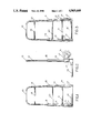
- FIG. 4 A front view of the foldable luggage carrier 10 is shown in FIG. 4 with the carrier in the folded configuration.
- the wheels 15 and support brackets 14 are rotated inwardly and the luggage support arm 16 folded upwards into the vertical position.
- the upper frame structure 12, with horizontal brace 19, is folded downwards by means of hinges 28 coupling the upper frame to the lower frame and horizontal braces 10 and 11.
- the rotary motion conversion bracket 17 is shown in the folded position:
- FIG. 5 is a left side view of FIG. 4 showing the upper frame structure 12 and the lower frames structure 13 with coupling hinges 28 and hinge locking tube 18 raised to permit hinge operation.
- the luggage support frame 16 is shown in the upward position, the wheel support bracket 14 is shown with the rotary motion converter bracket 17.
- FIG. 6 is a detailed view of the rotary motion conversion bracket 17 in the folded position.
- the bracket 17 rotatable around the hinge pin 27 has a cam slot 31 which engages the radial pin 26 extending from the hub 24 and which serves to fasten the hub 24 to the rotatable tube frame member 34.
- the hinge pin 27 extends through orifices in the bracket 23 which is rotatable around the rotatable tube frame member 34.
- the wheel support bracket 14 is fastened to the rotatable tube frame member 34 by rivets 33 or other fastened to the rotatable tube frame member 34 by rivets 33 or other suitable means.
- the luggage support bracket 16 is shown extending from the bracket 17 with the position locking protrusion 30.
- FIG. 7 is a detailed view of the rotary motion conversion apparatus 17 rotated around the hinge pin 27 with the cam slot 31 engaging the radial pin 26 to rotate the hub 24, the rotatable tube frame member 34 and the wheel support bracket 14 to extend the wheels into the open position and engaging the protrusion 30 between the side walls of the bracket 14.
- FIG. 8 is a detailed view if the pin support orifice 32 in the bracket 23, the hub 24 with radial pin 26 and rotatable tube frame member 34.
- FIG. 9 is a bottom view of the rotary motion conversion bracket showing the wheel support bracket 14, the hub 24, the rotatable tube frame member 34, the radial pin 26 and the luggage support frame 16 with fastening rivets 29.
- FIG. 10 shows a side view of the hinge 28 with clevis 21 in the top structure 12 and the bottom basic frame member 13 with the clevis 22.
- the slidable lock tube 18 is shown in the upper or unlocked position.
- FIG. 11 is a front view of the hinge 28 with upper portion 25 in the clevis 21 and the lower portion 25 in the clevis 22 in the basic frame member 12.
- FIG. 12 is a left end view of FIG. 7 showing the bracket 17 with protrusion 30 engaging the side walls of the wheel support bracket 14 with radial pin 26 engaging the cam slot 31, the rotatable tube frame member 34 with flange 35 supported by circular slot 35 and ring 36.
Landscapes
- Engineering & Computer Science (AREA)
- Chemical & Material Sciences (AREA)
- Combustion & Propulsion (AREA)
- Transportation (AREA)
- Mechanical Engineering (AREA)
- Handcart (AREA)
Abstract
A light weight, foldable, luggage carrier capable of being folded to a flat package storable beneath the seat of an airplane or a train. The carrier having larger than normal diameter wheels whose axis rotates inwardly between the frame members when the luggage support frame is raised to the closed or stored position. This conversion of the carrier from the open to the closed position can be accomplished by the use of one hand.
Description
This is a continuation-in-part of U.S. patent application Ser. No. 07,381,062 filed 07/17/89, now abandoned.
1. Field of the Invention
This invention relates to a hand-truck and more particularly to a hand-truck that when empty can be folded into a compact unit flat enough to be stored beneath the seat of an aircraft or train.
2. Description of the Prior Art
U.S. Pat. No. 3,947,054 Hall, describes a folding luggage carrier, with a folding handle and small wheels, that easily folds for storage beneath an aircraft passenger seat.
U.S. Pat. No. 4,299,403 Brewer et al describes a wheeled baggage carrier with foldable handle and foldable platform of truss-like configuration. U.S. Pat. No. 4,062,565 Holtz, describes a collapsible baggage cart as tubular configuration with a foldable handle and a foldable platform. The U.S. Pat. No. 3,043,603 Major, Sr., describes a hand-truck with pivoted wheel supports.
The principal objectives of the instant invention is to provide a luggage carrier foldable into a flat configuration that will fit beneath the seat of a passenger aircraft. The luggage carrier capable of being opened for use and locked in the open position by folding down the luggage platform. The limiting factor in obtaining a flat package for many luggage carriers is the diameter of the wheels, thus necessitating the use of impractical small wheels. The instant invention provides pivoted wheel support, allowing the wheels to swing inwardly parallel to the luggage carrier frame. This arrangement permits the use of a larger wheel diameter, for traversing uneven surfaces.
A second limiting factor in obtaining a flat package in the configuration of the handle hinge assembly. The instant invention describes a hinge assembly of the same outside dimensions as the carrier frame member.
Luggage carriers currently available having pivoted wheel supports and foldable platforms require the use of two hands in order to swing each wheel outwardly and to fold down the platform. The instant invention utilizes a motion conversion device coupled between the platform hinge and the pivoted wheel support that simultaneously rotates the wheels as the platform is lowered into position by one hand.
The instant invention describes a luggage carrier with a tubular substantially rectangular basic frame with a pair of wheels rotatable around the vertical axis attached to two adjacent corners. A second frame of similar construction is hinged to the top of the basic frame so as to be capable of extending the basic frame into a coplanar position. A rectangular tubular frame attached to the basic frame near the wheels supports luggage stacked onto the carrier. The rotatable wheel supports which are angularly movable from an extended position to a folded position are mounted on the lower end of the main support structure. The wheel supports are rotatable around the tubular support structure by means of a vertical slot engaging an extended section extending upwardly from the platform hinge which rotates around a diametric pin extending from the tubular support.
FIG. 1 is a front view of the foldable luggage carrier;
FIG. 2 is a right side view of the foldable luggage carrier;
FIG. 3 is a back view of the foldable luggage carrier;
FIG. 4 is a front view of the foldable luggage carrier in the folded configuration;
FIG. 5 is a left side view of the foldable luggage carrier in the folded configuration
FIG. 6 is a detailed side view of the rotary motion conversion bracket in the folded configuration;
FIG. 7 is a detailed side view of the rotary motion conversion bracket in the open configuration;
FIG. 8 is a detailed view of the motion conversion rotary hub;
FIG. 9 is a bottom view of the rotary motion conversion bracket;
FIG. 10 is a detailed front view of the handle hinge;
FIG. 11 is a detailed side view of the handle hinge;
FIG. 12 is an end view of the rotary motion conversion bracket.
Referring to FIG. 1 the foldable luggage carrier 10 is shown in a front view with the second or upper frame structure 12 with horizontal brace 19 hinged to the lower basic frame structure 13 with horizontal braces 20 and 11. The slidable hinge lock tube 18 is shown in the locked position. Rotatable around the tubular structure 13 are the wheel support brackets 14 with luggage support frame 16 hinged vertically to the tubular structure 13 by rotary motion conversion bracket 17.
The side view of FIG. 2 shows the luggage carrier 10 with upper frame 12, the hinge lock tube 18, lower basic frame 13 with rotatable wheel support bracket 14 supporting the wheel 15. The rotary motion conversion bracket 17 is shown with attached luggage support frame 16.
The rear view of FIG. 3 shows the luggage carrier 10 with the upper frame structure 12, with horizontal brace 19, hinged to the lower tubular vertical support structure 13 with horizontal braces 20 and 11. The hinge covered by slidable lock tube 18 is shown in the locked position. Rotatable around the tubular structure 13 are the wheel support brackets 14 with the wheels 15, the rotary motion conversion bracket 17 and the luggage arm 16.
A front view of the foldable luggage carrier 10 is shown in FIG. 4 with the carrier in the folded configuration. The wheels 15 and support brackets 14 are rotated inwardly and the luggage support arm 16 folded upwards into the vertical position. The upper frame structure 12, with horizontal brace 19, is folded downwards by means of hinges 28 coupling the upper frame to the lower frame and horizontal braces 10 and 11. The rotary motion conversion bracket 17 is shown in the folded position:
FIG. 5 is a left side view of FIG. 4 showing the upper frame structure 12 and the lower frames structure 13 with coupling hinges 28 and hinge locking tube 18 raised to permit hinge operation. The luggage support frame 16 is shown in the upward position, the wheel support bracket 14 is shown with the rotary motion converter bracket 17.
FIG. 6 is a detailed view of the rotary motion conversion bracket 17 in the folded position. The bracket 17 rotatable around the hinge pin 27 has a cam slot 31 which engages the radial pin 26 extending from the hub 24 and which serves to fasten the hub 24 to the rotatable tube frame member 34. The hinge pin 27 extends through orifices in the bracket 23 which is rotatable around the rotatable tube frame member 34. The wheel support bracket 14 is fastened to the rotatable tube frame member 34 by rivets 33 or other fastened to the rotatable tube frame member 34 by rivets 33 or other suitable means. The luggage support bracket 16 is shown extending from the bracket 17 with the position locking protrusion 30.
FIG. 7 is a detailed view of the rotary motion conversion apparatus 17 rotated around the hinge pin 27 with the cam slot 31 engaging the radial pin 26 to rotate the hub 24, the rotatable tube frame member 34 and the wheel support bracket 14 to extend the wheels into the open position and engaging the protrusion 30 between the side walls of the bracket 14.
FIG. 8 is a detailed view if the pin support orifice 32 in the bracket 23, the hub 24 with radial pin 26 and rotatable tube frame member 34.
FIG. 9 is a bottom view of the rotary motion conversion bracket showing the wheel support bracket 14, the hub 24, the rotatable tube frame member 34, the radial pin 26 and the luggage support frame 16 with fastening rivets 29.
FIG. 10 shows a side view of the hinge 28 with clevis 21 in the top structure 12 and the bottom basic frame member 13 with the clevis 22. The slidable lock tube 18 is shown in the upper or unlocked position.
FIG. 11 is a front view of the hinge 28 with upper portion 25 in the clevis 21 and the lower portion 25 in the clevis 22 in the basic frame member 12.
FIG. 12 is a left end view of FIG. 7 showing the bracket 17 with protrusion 30 engaging the side walls of the wheel support bracket 14 with radial pin 26 engaging the cam slot 31, the rotatable tube frame member 34 with flange 35 supported by circular slot 35 and ring 36.
In use, rotating the luggage frame and bracket clockwise, or downwardly, around the hinge pin 27 rotates cam slot 31 to rotate radial pin 26 with the hub 24 and the rotatable tube member 34 clockwise around the vertical axis of the basic frame member 13. The wheel support bracket fastened to the rotatable tube member 34 is rotated clockwise with the hub 24 rotating the wheel support bracket 90 degrees to engage the protrusion 30 in the space between the side walls of the wheel support bracket 14.
Claims (1)
1. A foldable luggage carrier comprising:
a lower frame having a pair of spaced vertical tubular frame members and a plurality of horizontal braces interconnecting the tubular frame members;
an upper frame of tubular construction and having an inverted U-shaped configuration;
hinge means for pivotally connecting said lower frame to said upper frame, including clevises located at the lower ends of lower frame, and linking members interconnecting the clevises of said upper frame to respective clevises of said lower frame;
tubular locking members slidable over said hinge means and adjacent portions of said upper and lower frames for selectively locking said upper and lower frames in an extended operable position;
a U-shaped luggage support frame of tubular construction having a pair of spaced legs and a central portion;
a rotary motion conversion bracket pivotally attached to a lower end of each said vertical tubular frame member, each said rotary motion conversion bracket having a U-shaped configuration with a pair of spaced legs and a curved central portion, a free end of each leg of said luggage support frame being rigidly connected between the spaced legs of a respective one of said rotary motion conversion brackets, and a curved cam slot formed in each said rotary motion conversion bracket;
a wheel support bracket pivotally attached to a lower portion of each said vertical tubular frame member, each said wheel support bracket having a U-shaped configuration with a pair of spaced legs and a curved central portion, said central portion of said wheel support bracket encircling said vertical tubular frame member, and a wheel rotatably supported between said pair of spaced legs of each said wheel support bracket; and
a rotatable hub extending axially through each said vertical tubular frame member, each said wheel support bracket being secured to a respective hub for rotation therewith, each said hub having a lower portion extending into a respective one of said rotary motion conversion brackets and a pin extending radially outwardly from said lower portion, said pin extending through said cam slot of said rotary motion conversion bracket for causing rotary motion of said hub, with said wheel support bracket attached thereto, in response to pivotal movement of said luggage support frame relative to said lower frame.
Applications Claiming Priority (1)
| Application Number | Priority Date | Filing Date | Title |
|---|---|---|---|
| US38106289A | 1989-07-17 | 1989-07-17 |
Related Parent Applications (1)
| Application Number | Title | Priority Date | Filing Date |
|---|---|---|---|
| US38106289A Continuation-In-Part | 1989-07-17 | 1989-07-17 |
Publications (1)
| Publication Number | Publication Date |
|---|---|
| US4969660A true US4969660A (en) | 1990-11-13 |
Family
ID=23503513
Family Applications (1)
| Application Number | Title | Priority Date | Filing Date |
|---|---|---|---|
| US07/509,990 Expired - Fee Related US4969660A (en) | 1989-07-17 | 1990-03-29 | Foldable luggage carrier |
Country Status (1)
| Country | Link |
|---|---|
| US (1) | US4969660A (en) |
Cited By (32)
| Publication number | Priority date | Publication date | Assignee | Title |
|---|---|---|---|---|
| US5127662A (en) * | 1990-08-13 | 1992-07-07 | Jay Spak | Attachable foldable luggage carrier |
| US5312006A (en) * | 1992-06-02 | 1994-05-17 | Lag Fang Hoang | Foldable carriage rack |
| US5326116A (en) * | 1992-09-14 | 1994-07-05 | Nathan Flax | Foldable hand trolley and associated method of use |
| US5348325A (en) * | 1991-10-11 | 1994-09-20 | Martin Abrams | Portable, collapsible luggage carrier |
| US5401043A (en) * | 1993-10-25 | 1995-03-28 | Myron; Gordon D. | Collapsible cart |
| US5547053A (en) * | 1994-09-08 | 1996-08-20 | Liang; Joseph | Spring loaded luggage handle |
| US5626351A (en) * | 1995-06-16 | 1997-05-06 | Tsai; Cheng-Hsien | Collapsible hand cart |
| US5765702A (en) * | 1997-03-04 | 1998-06-16 | L&P Property Management Company | Wheeled merchandise display rack |
| US5803471A (en) * | 1997-05-23 | 1998-09-08 | Demars; Robert A. | Collapsible dolly |
| US5957472A (en) * | 1997-07-31 | 1999-09-28 | Power Tool Specialists, Inc. | Apparatus forming a combined hand truck and machine stand |
| US6102433A (en) * | 1999-10-15 | 2000-08-15 | Stevens; Terence | Compact cart |
| US6135466A (en) * | 1997-12-09 | 2000-10-24 | Irwin; Lawrence F. | Transport dolly for lifting and transporting lavatory fixtures |
| WO2002006105A1 (en) * | 2000-07-17 | 2002-01-24 | Magline, Inc. | Vertically folding hand truck and methods of its operation and construction |
| US20050258621A1 (en) * | 2004-05-18 | 2005-11-24 | Chris Johnson | Portable luggage carts/carriers |
| US20060071436A1 (en) * | 2004-06-22 | 2006-04-06 | O'connor Charles S | Convertible carrying case systems and collapsible wheeled carts for carrying cases |
| US20060199672A1 (en) * | 2005-03-03 | 2006-09-07 | Flanigan George R | Batting tee |
| US20070072738A1 (en) * | 2005-09-26 | 2007-03-29 | Fen-Ying Lai | Foldable trampoline |
| US7255658B1 (en) * | 2005-09-13 | 2007-08-14 | Vankuiken Jack C | Baseball equipment bucket and pitching target |
| US20080197591A1 (en) * | 2007-02-16 | 2008-08-21 | Haiming Tsai | Hand truck |
| US20090051133A1 (en) * | 2007-08-22 | 2009-02-26 | Danny Oshiro | Dolly Apparatus For Bag Toss Game |
| EP1561665A3 (en) * | 2004-01-30 | 2009-08-12 | Jaime Garcia Moll, S.L. | Folding shopping trolley |
| US20100066057A1 (en) * | 2008-09-12 | 2010-03-18 | Jian Shikun | Flat platform cart with collapsible casters |
| US20110175308A1 (en) * | 2010-01-19 | 2011-07-21 | Haiming Tsai | Handcart |
| US20110175307A1 (en) * | 2010-01-19 | 2011-07-21 | Haiming Tsai | Handcart |
| US20120038123A1 (en) * | 2010-08-11 | 2012-02-16 | Hong Min Li | Hand truck with adjustable wheel assembly |
| US8602444B2 (en) * | 2011-12-09 | 2013-12-10 | Seville Classics Inc. | Foldable hand cart |
| US20140265192A1 (en) * | 2012-05-11 | 2014-09-18 | Hai-Ming Tsai | Hand trolley with a load tray co-working with wheel sets |
| EP2381061A3 (en) * | 2010-04-23 | 2015-09-23 | Lin, Shih-ming | Ladder assembly having the function of a carrier |
| US9888752B2 (en) | 2012-07-09 | 2018-02-13 | Royalty Bugaboo Gmbh | Luggage item, a luggage item system, a luggage item adaptor |
| US10005481B1 (en) | 2016-11-23 | 2018-06-26 | Albert Manuel Lopez | Dolly for field technicians |
| US10130150B2 (en) | 2013-10-03 | 2018-11-20 | Royalty Bugaboo Gmbh | Luggage assembly and a frame |
| US11110948B2 (en) * | 2019-03-29 | 2021-09-07 | Jae Ho Song | Four-wheeled folding handcart |
Citations (9)
| Publication number | Priority date | Publication date | Assignee | Title |
|---|---|---|---|---|
| US3043603A (en) * | 1959-06-08 | 1962-07-10 | Sr Raymond J Major | Hand truck with pivoted wheel supports |
| US3197226A (en) * | 1963-12-17 | 1965-07-27 | Atwood E Erlinder | Folding luggage carrier |
| US3241852A (en) * | 1964-07-17 | 1966-03-22 | Joseph F Muller | Folding cart for outboard motors |
| US3947054A (en) * | 1974-11-04 | 1976-03-30 | Herbert Charles Hall | Folding luggage carrier |
| US4037858A (en) * | 1975-10-20 | 1977-07-26 | Adams John F | Portable luggage carrier |
| US4062565A (en) * | 1976-11-01 | 1977-12-13 | Holtz Gilbert J | Collapsible baggage cart |
| US4299403A (en) * | 1979-11-09 | 1981-11-10 | Hamilton C. de Jong | Wheeled carrier for hand luggage and the like |
| US4315632A (en) * | 1980-05-27 | 1982-02-16 | Taylor Frank E | Folding two-wheeled hand truck |
| US4754985A (en) * | 1986-10-20 | 1988-07-05 | Im Byung Do | Luggage carrier |
-
1990
- 1990-03-29 US US07/509,990 patent/US4969660A/en not_active Expired - Fee Related
Patent Citations (9)
| Publication number | Priority date | Publication date | Assignee | Title |
|---|---|---|---|---|
| US3043603A (en) * | 1959-06-08 | 1962-07-10 | Sr Raymond J Major | Hand truck with pivoted wheel supports |
| US3197226A (en) * | 1963-12-17 | 1965-07-27 | Atwood E Erlinder | Folding luggage carrier |
| US3241852A (en) * | 1964-07-17 | 1966-03-22 | Joseph F Muller | Folding cart for outboard motors |
| US3947054A (en) * | 1974-11-04 | 1976-03-30 | Herbert Charles Hall | Folding luggage carrier |
| US4037858A (en) * | 1975-10-20 | 1977-07-26 | Adams John F | Portable luggage carrier |
| US4062565A (en) * | 1976-11-01 | 1977-12-13 | Holtz Gilbert J | Collapsible baggage cart |
| US4299403A (en) * | 1979-11-09 | 1981-11-10 | Hamilton C. de Jong | Wheeled carrier for hand luggage and the like |
| US4315632A (en) * | 1980-05-27 | 1982-02-16 | Taylor Frank E | Folding two-wheeled hand truck |
| US4754985A (en) * | 1986-10-20 | 1988-07-05 | Im Byung Do | Luggage carrier |
Cited By (44)
| Publication number | Priority date | Publication date | Assignee | Title |
|---|---|---|---|---|
| US5127662A (en) * | 1990-08-13 | 1992-07-07 | Jay Spak | Attachable foldable luggage carrier |
| US5348325A (en) * | 1991-10-11 | 1994-09-20 | Martin Abrams | Portable, collapsible luggage carrier |
| US5312006A (en) * | 1992-06-02 | 1994-05-17 | Lag Fang Hoang | Foldable carriage rack |
| US5326116A (en) * | 1992-09-14 | 1994-07-05 | Nathan Flax | Foldable hand trolley and associated method of use |
| US5401043A (en) * | 1993-10-25 | 1995-03-28 | Myron; Gordon D. | Collapsible cart |
| US5547053A (en) * | 1994-09-08 | 1996-08-20 | Liang; Joseph | Spring loaded luggage handle |
| US5626351A (en) * | 1995-06-16 | 1997-05-06 | Tsai; Cheng-Hsien | Collapsible hand cart |
| US5765702A (en) * | 1997-03-04 | 1998-06-16 | L&P Property Management Company | Wheeled merchandise display rack |
| US5803471A (en) * | 1997-05-23 | 1998-09-08 | Demars; Robert A. | Collapsible dolly |
| US5957472A (en) * | 1997-07-31 | 1999-09-28 | Power Tool Specialists, Inc. | Apparatus forming a combined hand truck and machine stand |
| US6135466A (en) * | 1997-12-09 | 2000-10-24 | Irwin; Lawrence F. | Transport dolly for lifting and transporting lavatory fixtures |
| US6102433A (en) * | 1999-10-15 | 2000-08-15 | Stevens; Terence | Compact cart |
| WO2002006105A1 (en) * | 2000-07-17 | 2002-01-24 | Magline, Inc. | Vertically folding hand truck and methods of its operation and construction |
| US6601859B2 (en) | 2000-07-17 | 2003-08-05 | Magline, Inc. | Vertically folding hand truck and methods of its operation and construction |
| EP1174327A3 (en) * | 2000-07-17 | 2003-11-19 | Magline, Inc | Vertically folding hand truck and methods of its operation and construction |
| EP1561665A3 (en) * | 2004-01-30 | 2009-08-12 | Jaime Garcia Moll, S.L. | Folding shopping trolley |
| US20050258621A1 (en) * | 2004-05-18 | 2005-11-24 | Chris Johnson | Portable luggage carts/carriers |
| US7140635B2 (en) * | 2004-05-18 | 2006-11-28 | Franzus Company Llc | Portable luggage carts/carriers |
| US20060071436A1 (en) * | 2004-06-22 | 2006-04-06 | O'connor Charles S | Convertible carrying case systems and collapsible wheeled carts for carrying cases |
| US7614628B2 (en) | 2004-06-22 | 2009-11-10 | Ezm, Inc. | Convertible carrying case systems and collapsible wheeled carts for carrying cases |
| US20060199672A1 (en) * | 2005-03-03 | 2006-09-07 | Flanigan George R | Batting tee |
| US7226372B2 (en) * | 2005-03-03 | 2007-06-05 | Flanigan George R | Batting tee |
| US7255658B1 (en) * | 2005-09-13 | 2007-08-14 | Vankuiken Jack C | Baseball equipment bucket and pitching target |
| US20070072738A1 (en) * | 2005-09-26 | 2007-03-29 | Fen-Ying Lai | Foldable trampoline |
| US7468020B2 (en) * | 2005-09-26 | 2008-12-23 | Fen-Ying Lai | Foldable trampoline |
| US20080197591A1 (en) * | 2007-02-16 | 2008-08-21 | Haiming Tsai | Hand truck |
| US7600765B2 (en) * | 2007-02-16 | 2009-10-13 | Haiming Tsai | Hand truck |
| US20090051133A1 (en) * | 2007-08-22 | 2009-02-26 | Danny Oshiro | Dolly Apparatus For Bag Toss Game |
| US20100066057A1 (en) * | 2008-09-12 | 2010-03-18 | Jian Shikun | Flat platform cart with collapsible casters |
| US7784816B2 (en) * | 2008-09-12 | 2010-08-31 | Jian Shikun | Flat platform cart with collapsible casters |
| US8454033B2 (en) * | 2010-01-19 | 2013-06-04 | Haiming Tsai | Handcart |
| US8100417B2 (en) * | 2010-01-19 | 2012-01-24 | Haiming Tsai | Handcart |
| US20110175308A1 (en) * | 2010-01-19 | 2011-07-21 | Haiming Tsai | Handcart |
| US20110175307A1 (en) * | 2010-01-19 | 2011-07-21 | Haiming Tsai | Handcart |
| EP2381061A3 (en) * | 2010-04-23 | 2015-09-23 | Lin, Shih-ming | Ladder assembly having the function of a carrier |
| US20120038123A1 (en) * | 2010-08-11 | 2012-02-16 | Hong Min Li | Hand truck with adjustable wheel assembly |
| US8770598B2 (en) * | 2010-08-11 | 2014-07-08 | Hong Min Li | Hand truck with adjustable wheel assembly |
| US8602444B2 (en) * | 2011-12-09 | 2013-12-10 | Seville Classics Inc. | Foldable hand cart |
| US20140265192A1 (en) * | 2012-05-11 | 2014-09-18 | Hai-Ming Tsai | Hand trolley with a load tray co-working with wheel sets |
| US8936259B2 (en) * | 2012-05-11 | 2015-01-20 | Hai-Ming Tsai | Hand trolley with a load tray co-working with wheel sets |
| US9888752B2 (en) | 2012-07-09 | 2018-02-13 | Royalty Bugaboo Gmbh | Luggage item, a luggage item system, a luggage item adaptor |
| US10130150B2 (en) | 2013-10-03 | 2018-11-20 | Royalty Bugaboo Gmbh | Luggage assembly and a frame |
| US10005481B1 (en) | 2016-11-23 | 2018-06-26 | Albert Manuel Lopez | Dolly for field technicians |
| US11110948B2 (en) * | 2019-03-29 | 2021-09-07 | Jae Ho Song | Four-wheeled folding handcart |
Similar Documents
| Publication | Publication Date | Title |
|---|---|---|
| US4969660A (en) | Foldable luggage carrier | |
| US3873117A (en) | Foldable baby carriage construction | |
| US4448434A (en) | Collapsible hand truck | |
| US5454576A (en) | Foldable two-wheeled golf pull cart | |
| US5090725A (en) | Collapsible garment cart | |
| US5127662A (en) | Attachable foldable luggage carrier | |
| US4659096A (en) | Carriage device | |
| US7731221B2 (en) | Collapsible and portable wheeled dolly particularly suitable for use by students or others in the transport of items | |
| US5348325A (en) | Portable, collapsible luggage carrier | |
| US3459435A (en) | Baby strollers | |
| US5161811A (en) | Trolley with a foldable seat assembly | |
| US5544904A (en) | Convertible stroller | |
| US4784401A (en) | Collapsible caddie cart | |
| US20140028001A1 (en) | Collapsible pushchair | |
| WO2017153980A1 (en) | Convertible stroller | |
| US20140159346A1 (en) | Stroller with expandable cargo area | |
| US20190135323A1 (en) | Convertible Stroller | |
| US6746079B2 (en) | Folding seat assemblage to attach to a luggage cart and its deployment linkage | |
| CN207311555U (en) | Bi-directional foldable stroller | |
| US20040207240A1 (en) | Collapsible wheeled dual-chair | |
| US2507234A (en) | Carrier stand for outboard motors | |
| GB2113625A (en) | Collapsible trolley | |
| GB2292354A (en) | Folding pushchair: downward rotation of handle reduces wheelbase. | |
| GB2221429A (en) | Collapsible hand trolley | |
| CN111361625A (en) | Foldable baby carriage |
Legal Events
| Date | Code | Title | Description |
|---|---|---|---|
| REMI | Maintenance fee reminder mailed | ||
| FPAY | Fee payment |
Year of fee payment: 4 |
|
| SULP | Surcharge for late payment | ||
| FPAY | Fee payment |
Year of fee payment: 8 |
|
| REMI | Maintenance fee reminder mailed | ||
| LAPS | Lapse for failure to pay maintenance fees | ||
| STCH | Information on status: patent discontinuation |
Free format text: PATENT EXPIRED DUE TO NONPAYMENT OF MAINTENANCE FEES UNDER 37 CFR 1.362 |
|
| FP | Lapsed due to failure to pay maintenance fee |
Effective date: 20021113 |