US4961043A - Battery conditioning system having communication with battery parameter memory means in conjunction with battery conditioning - Google Patents
Battery conditioning system having communication with battery parameter memory means in conjunction with battery conditioning Download PDFInfo
- Publication number
- US4961043A US4961043A US07/422,226 US42222689A US4961043A US 4961043 A US4961043 A US 4961043A US 42222689 A US42222689 A US 42222689A US 4961043 A US4961043 A US 4961043A
- Authority
- US
- United States
- Prior art keywords
- battery
- conditioning
- portable
- control signal
- charging
- Prior art date
- Legal status (The legal status is an assumption and is not a legal conclusion. Google has not performed a legal analysis and makes no representation as to the accuracy of the status listed.)
- Expired - Lifetime
Links
Images


Classifications
-
- H—ELECTRICITY
- H01—ELECTRIC ELEMENTS
- H01M—PROCESSES OR MEANS, e.g. BATTERIES, FOR THE DIRECT CONVERSION OF CHEMICAL ENERGY INTO ELECTRICAL ENERGY
- H01M6/00—Primary cells; Manufacture thereof
- H01M6/50—Methods or arrangements for servicing or maintenance, e.g. for maintaining operating temperature
- H01M6/5044—Cells or batteries structurally combined with cell condition indicating means
- H01M6/505—Cells combined with indicating means for external visualization of the condition, e.g. by change of colour or of light intensity
-
- G—PHYSICS
- G06—COMPUTING; CALCULATING OR COUNTING
- G06F—ELECTRIC DIGITAL DATA PROCESSING
- G06F1/00—Details not covered by groups G06F3/00 - G06F13/00 and G06F21/00
- G06F1/26—Power supply means, e.g. regulation thereof
- G06F1/263—Arrangements for using multiple switchable power supplies, e.g. battery and AC
-
- H—ELECTRICITY
- H01—ELECTRIC ELEMENTS
- H01M—PROCESSES OR MEANS, e.g. BATTERIES, FOR THE DIRECT CONVERSION OF CHEMICAL ENERGY INTO ELECTRICAL ENERGY
- H01M10/00—Secondary cells; Manufacture thereof
- H01M10/42—Methods or arrangements for servicing or maintenance of secondary cells or secondary half-cells
- H01M10/425—Structural combination with electronic components, e.g. electronic circuits integrated to the outside of the casing
- H01M10/4257—Smart batteries, e.g. electronic circuits inside the housing of the cells or batteries
-
- H—ELECTRICITY
- H01—ELECTRIC ELEMENTS
- H01M—PROCESSES OR MEANS, e.g. BATTERIES, FOR THE DIRECT CONVERSION OF CHEMICAL ENERGY INTO ELECTRICAL ENERGY
- H01M10/00—Secondary cells; Manufacture thereof
- H01M10/42—Methods or arrangements for servicing or maintenance of secondary cells or secondary half-cells
- H01M10/48—Accumulators combined with arrangements for measuring, testing or indicating the condition of cells, e.g. the level or density of the electrolyte
-
- H—ELECTRICITY
- H01—ELECTRIC ELEMENTS
- H01M—PROCESSES OR MEANS, e.g. BATTERIES, FOR THE DIRECT CONVERSION OF CHEMICAL ENERGY INTO ELECTRICAL ENERGY
- H01M50/00—Constructional details or processes of manufacture of the non-active parts of electrochemical cells other than fuel cells, e.g. hybrid cells
- H01M50/20—Mountings; Secondary casings or frames; Racks, modules or packs; Suspension devices; Shock absorbers; Transport or carrying devices; Holders
- H01M50/204—Racks, modules or packs for multiple batteries or multiple cells
- H01M50/207—Racks, modules or packs for multiple batteries or multiple cells characterised by their shape
- H01M50/213—Racks, modules or packs for multiple batteries or multiple cells characterised by their shape adapted for cells having curved cross-section, e.g. round or elliptic
-
- H—ELECTRICITY
- H02—GENERATION; CONVERSION OR DISTRIBUTION OF ELECTRIC POWER
- H02J—CIRCUIT ARRANGEMENTS OR SYSTEMS FOR SUPPLYING OR DISTRIBUTING ELECTRIC POWER; SYSTEMS FOR STORING ELECTRIC ENERGY
- H02J7/00—Circuit arrangements for charging or depolarising batteries or for supplying loads from batteries
- H02J7/00032—Circuit arrangements for charging or depolarising batteries or for supplying loads from batteries characterised by data exchange
- H02J7/00036—Charger exchanging data with battery
-
- H—ELECTRICITY
- H02—GENERATION; CONVERSION OR DISTRIBUTION OF ELECTRIC POWER
- H02J—CIRCUIT ARRANGEMENTS OR SYSTEMS FOR SUPPLYING OR DISTRIBUTING ELECTRIC POWER; SYSTEMS FOR STORING ELECTRIC ENERGY
- H02J7/00—Circuit arrangements for charging or depolarising batteries or for supplying loads from batteries
- H02J7/00032—Circuit arrangements for charging or depolarising batteries or for supplying loads from batteries characterised by data exchange
- H02J7/00038—Circuit arrangements for charging or depolarising batteries or for supplying loads from batteries characterised by data exchange using passive battery identification means, e.g. resistors or capacitors
-
- H—ELECTRICITY
- H02—GENERATION; CONVERSION OR DISTRIBUTION OF ELECTRIC POWER
- H02J—CIRCUIT ARRANGEMENTS OR SYSTEMS FOR SUPPLYING OR DISTRIBUTING ELECTRIC POWER; SYSTEMS FOR STORING ELECTRIC ENERGY
- H02J7/00—Circuit arrangements for charging or depolarising batteries or for supplying loads from batteries
- H02J7/00047—Circuit arrangements for charging or depolarising batteries or for supplying loads from batteries with provisions for charging different types of batteries
-
- H—ELECTRICITY
- H02—GENERATION; CONVERSION OR DISTRIBUTION OF ELECTRIC POWER
- H02J—CIRCUIT ARRANGEMENTS OR SYSTEMS FOR SUPPLYING OR DISTRIBUTING ELECTRIC POWER; SYSTEMS FOR STORING ELECTRIC ENERGY
- H02J7/00—Circuit arrangements for charging or depolarising batteries or for supplying loads from batteries
- H02J7/0047—Circuit arrangements for charging or depolarising batteries or for supplying loads from batteries with monitoring or indicating devices or circuits
-
- H—ELECTRICITY
- H02—GENERATION; CONVERSION OR DISTRIBUTION OF ELECTRIC POWER
- H02J—CIRCUIT ARRANGEMENTS OR SYSTEMS FOR SUPPLYING OR DISTRIBUTING ELECTRIC POWER; SYSTEMS FOR STORING ELECTRIC ENERGY
- H02J7/00—Circuit arrangements for charging or depolarising batteries or for supplying loads from batteries
- H02J7/0068—Battery or charger load switching, e.g. concurrent charging and load supply
-
- H—ELECTRICITY
- H02—GENERATION; CONVERSION OR DISTRIBUTION OF ELECTRIC POWER
- H02J—CIRCUIT ARRANGEMENTS OR SYSTEMS FOR SUPPLYING OR DISTRIBUTING ELECTRIC POWER; SYSTEMS FOR STORING ELECTRIC ENERGY
- H02J7/00—Circuit arrangements for charging or depolarising batteries or for supplying loads from batteries
- H02J7/0069—Charging or discharging for charge maintenance, battery initiation or rejuvenation
-
- H—ELECTRICITY
- H02—GENERATION; CONVERSION OR DISTRIBUTION OF ELECTRIC POWER
- H02J—CIRCUIT ARRANGEMENTS OR SYSTEMS FOR SUPPLYING OR DISTRIBUTING ELECTRIC POWER; SYSTEMS FOR STORING ELECTRIC ENERGY
- H02J7/00—Circuit arrangements for charging or depolarising batteries or for supplying loads from batteries
- H02J7/007—Regulation of charging or discharging current or voltage
- H02J7/0071—Regulation of charging or discharging current or voltage with a programmable schedule
-
- H—ELECTRICITY
- H02—GENERATION; CONVERSION OR DISTRIBUTION OF ELECTRIC POWER
- H02J—CIRCUIT ARRANGEMENTS OR SYSTEMS FOR SUPPLYING OR DISTRIBUTING ELECTRIC POWER; SYSTEMS FOR STORING ELECTRIC ENERGY
- H02J7/00—Circuit arrangements for charging or depolarising batteries or for supplying loads from batteries
- H02J7/007—Regulation of charging or discharging current or voltage
- H02J7/00711—Regulation of charging or discharging current or voltage with introduction of pulses during the charging process
-
- H—ELECTRICITY
- H02—GENERATION; CONVERSION OR DISTRIBUTION OF ELECTRIC POWER
- H02J—CIRCUIT ARRANGEMENTS OR SYSTEMS FOR SUPPLYING OR DISTRIBUTING ELECTRIC POWER; SYSTEMS FOR STORING ELECTRIC ENERGY
- H02J7/00—Circuit arrangements for charging or depolarising batteries or for supplying loads from batteries
- H02J7/007—Regulation of charging or discharging current or voltage
- H02J7/00712—Regulation of charging or discharging current or voltage the cycle being controlled or terminated in response to electric parameters
- H02J7/00714—Regulation of charging or discharging current or voltage the cycle being controlled or terminated in response to electric parameters in response to battery charging or discharging current
-
- H—ELECTRICITY
- H02—GENERATION; CONVERSION OR DISTRIBUTION OF ELECTRIC POWER
- H02J—CIRCUIT ARRANGEMENTS OR SYSTEMS FOR SUPPLYING OR DISTRIBUTING ELECTRIC POWER; SYSTEMS FOR STORING ELECTRIC ENERGY
- H02J7/00—Circuit arrangements for charging or depolarising batteries or for supplying loads from batteries
- H02J7/007—Regulation of charging or discharging current or voltage
- H02J7/007188—Regulation of charging or discharging current or voltage the charge cycle being controlled or terminated in response to non-electric parameters
- H02J7/007192—Regulation of charging or discharging current or voltage the charge cycle being controlled or terminated in response to non-electric parameters in response to temperature
- H02J7/007194—Regulation of charging or discharging current or voltage the charge cycle being controlled or terminated in response to non-electric parameters in response to temperature of the battery
-
- H—ELECTRICITY
- H02—GENERATION; CONVERSION OR DISTRIBUTION OF ELECTRIC POWER
- H02J—CIRCUIT ARRANGEMENTS OR SYSTEMS FOR SUPPLYING OR DISTRIBUTING ELECTRIC POWER; SYSTEMS FOR STORING ELECTRIC ENERGY
- H02J9/00—Circuit arrangements for emergency or stand-by power supply, e.g. for emergency lighting
- H02J9/04—Circuit arrangements for emergency or stand-by power supply, e.g. for emergency lighting in which the distribution system is disconnected from the normal source and connected to a standby source
- H02J9/06—Circuit arrangements for emergency or stand-by power supply, e.g. for emergency lighting in which the distribution system is disconnected from the normal source and connected to a standby source with automatic change-over, e.g. UPS systems
- H02J9/061—Circuit arrangements for emergency or stand-by power supply, e.g. for emergency lighting in which the distribution system is disconnected from the normal source and connected to a standby source with automatic change-over, e.g. UPS systems for DC powered loads
-
- G—PHYSICS
- G01—MEASURING; TESTING
- G01R—MEASURING ELECTRIC VARIABLES; MEASURING MAGNETIC VARIABLES
- G01R31/00—Arrangements for testing electric properties; Arrangements for locating electric faults; Arrangements for electrical testing characterised by what is being tested not provided for elsewhere
- G01R31/36—Arrangements for testing, measuring or monitoring the electrical condition of accumulators or electric batteries, e.g. capacity or state of charge [SoC]
- G01R31/3644—Constructional arrangements
- G01R31/3648—Constructional arrangements comprising digital calculation means, e.g. for performing an algorithm
-
- G—PHYSICS
- G01—MEASURING; TESTING
- G01R—MEASURING ELECTRIC VARIABLES; MEASURING MAGNETIC VARIABLES
- G01R31/00—Arrangements for testing electric properties; Arrangements for locating electric faults; Arrangements for electrical testing characterised by what is being tested not provided for elsewhere
- G01R31/36—Arrangements for testing, measuring or monitoring the electrical condition of accumulators or electric batteries, e.g. capacity or state of charge [SoC]
- G01R31/374—Arrangements for testing, measuring or monitoring the electrical condition of accumulators or electric batteries, e.g. capacity or state of charge [SoC] with means for correcting the measurement for temperature or ageing
-
- G—PHYSICS
- G01—MEASURING; TESTING
- G01R—MEASURING ELECTRIC VARIABLES; MEASURING MAGNETIC VARIABLES
- G01R31/00—Arrangements for testing electric properties; Arrangements for locating electric faults; Arrangements for electrical testing characterised by what is being tested not provided for elsewhere
- G01R31/36—Arrangements for testing, measuring or monitoring the electrical condition of accumulators or electric batteries, e.g. capacity or state of charge [SoC]
- G01R31/382—Arrangements for monitoring battery or accumulator variables, e.g. SoC
- G01R31/3842—Arrangements for monitoring battery or accumulator variables, e.g. SoC combining voltage and current measurements
-
- H—ELECTRICITY
- H01—ELECTRIC ELEMENTS
- H01M—PROCESSES OR MEANS, e.g. BATTERIES, FOR THE DIRECT CONVERSION OF CHEMICAL ENERGY INTO ELECTRICAL ENERGY
- H01M50/00—Constructional details or processes of manufacture of the non-active parts of electrochemical cells other than fuel cells, e.g. hybrid cells
- H01M50/50—Current conducting connections for cells or batteries
-
- H—ELECTRICITY
- H01—ELECTRIC ELEMENTS
- H01M—PROCESSES OR MEANS, e.g. BATTERIES, FOR THE DIRECT CONVERSION OF CHEMICAL ENERGY INTO ELECTRICAL ENERGY
- H01M6/00—Primary cells; Manufacture thereof
- H01M6/50—Methods or arrangements for servicing or maintenance, e.g. for maintaining operating temperature
- H01M6/5044—Cells or batteries structurally combined with cell condition indicating means
-
- H—ELECTRICITY
- H02—GENERATION; CONVERSION OR DISTRIBUTION OF ELECTRIC POWER
- H02J—CIRCUIT ARRANGEMENTS OR SYSTEMS FOR SUPPLYING OR DISTRIBUTING ELECTRIC POWER; SYSTEMS FOR STORING ELECTRIC ENERGY
- H02J7/00—Circuit arrangements for charging or depolarising batteries or for supplying loads from batteries
- H02J7/0047—Circuit arrangements for charging or depolarising batteries or for supplying loads from batteries with monitoring or indicating devices or circuits
- H02J7/0048—Detection of remaining charge capacity or state of charge [SOC]
-
- H—ELECTRICITY
- H02—GENERATION; CONVERSION OR DISTRIBUTION OF ELECTRIC POWER
- H02J—CIRCUIT ARRANGEMENTS OR SYSTEMS FOR SUPPLYING OR DISTRIBUTING ELECTRIC POWER; SYSTEMS FOR STORING ELECTRIC ENERGY
- H02J7/00—Circuit arrangements for charging or depolarising batteries or for supplying loads from batteries
- H02J7/0047—Circuit arrangements for charging or depolarising batteries or for supplying loads from batteries with monitoring or indicating devices or circuits
- H02J7/005—Detection of state of health [SOH]
-
- Y—GENERAL TAGGING OF NEW TECHNOLOGICAL DEVELOPMENTS; GENERAL TAGGING OF CROSS-SECTIONAL TECHNOLOGIES SPANNING OVER SEVERAL SECTIONS OF THE IPC; TECHNICAL SUBJECTS COVERED BY FORMER USPC CROSS-REFERENCE ART COLLECTIONS [XRACs] AND DIGESTS
- Y02—TECHNOLOGIES OR APPLICATIONS FOR MITIGATION OR ADAPTATION AGAINST CLIMATE CHANGE
- Y02E—REDUCTION OF GREENHOUSE GAS [GHG] EMISSIONS, RELATED TO ENERGY GENERATION, TRANSMISSION OR DISTRIBUTION
- Y02E60/00—Enabling technologies; Technologies with a potential or indirect contribution to GHG emissions mitigation
- Y02E60/10—Energy storage using batteries
Definitions
- the present invention relates to a battery conditioning system for battery means of portable computerized devices, and particularly to a hand-held device including data storage means for storing data pertinent to the battery means of the device, and to a battery conditioning control system including an external charging circuit equipped for communication with data storage means of the hand-held device and/or of the battery means operatively associated with such device.
- the control system is capable of optimizing the performance of a rechargeable electrochemical storage medium while at the same time maximizing its useful life.
- the invention also relates to control systems generally, and to control systems forming part of hand-held units.
- Portable computerized systems are presently being extensively utilized in a wide range of applications. For example, such systems may be utilized in delivery vehicles which are to be away from a central warehouse or the like for a major part of each working day. Recharging operations may take place in locations subject to extremes of temperature. It is particularly crucial to avoid an equipment failure where a portable device is a vital link to the completion of scheduled tasks at remote locations and the like. In such circumstances, a loss of adequate battery power can be just as detrimental as any other malfunction.
- the battery conditioning control system is to be incorporated in hand-held devices, such control system should be lightweight and compact, and should consume minimum power.
- a microprocessor of a standard design and of minimum complexity is highly desirable.
- a further object of the present invention is to provide a control system particularly adapted to control battery conditioning of a variety of rechargeable battery means, automatically adaptable to hand-held devices having battery means of different types such as to require different conditioning parameters.
- Another object of the invention is to provide a charging current control system for battery powered portable devices which is not only lightweight and compact but which consumes minimum power, and which preferably is adapted to be implemented as an integrated circuit of an economical and simple construction.
- An exemplary feature of the invention resides in the provision of a battery conditioning system receptive of different hand-held devices and capable of communication therewith, e.g., to determine the type of conditioning required for respective different internal battery means thereof.
- a further feature of the invention relates to a battery conditioning system wherein the system can obtain a relatively accurate indication of the battery energy remaining available for use for one type or a plurality of different types of batteries, and supply the results to a memory means accompanying the battery means during portable operation.
- battery parameters including battery temperature can be monitored and transmitted to a conditioning system during a charging cycle, and the battery charging current can be adjusted accordingly.
- a count of such shallow charge cycles may be automatically maintained throughout the operating life of the battery system, such that deep discharge cycles may be effected as necessary to maintain desired performance standards.
- automatically operating battery monitoring and/or conditioning circuitry may be secured with the battery pack for handling as a unit therewith.
- the monitoring circuitry may receive its operating power from the battery pack during storage or handling such that a total history of the battery pack may be retained for example in a volatile memory circuit where such type of memory otherwise provides optimum characteristics for a portable system.
- the conditioning circuitry may have means for effecting a deep discharge cycle, and concomitantly with the deep discharge cycle, a measure of actual battery capacity may be obtained. From such measured battery capacity and a continuous measurement of battery current during portable operation, a relatively accurate "fuel gauge" function becomes feasible such that the risk of battery failure during field operation can be essentially eliminated. The performance of a given type of battery in actual use can be accurately judged since the battery system can itself maintain a count of accumulated hours of use, and other relevant parameters.
- the conditioning system is incorporated in the portable utilization device such that the programmed processor of the utilization device may itself automatically effect a deep discharge conditioning cycle and/or a deep discharge capacity test.
- the deep discharge cycle may be effected at a controlled rate, such that the time for discharge from a fully charged condition to a selected discharge condition may itself represent a measure of battery capacity.
- the programmed processor may maintain a measure of operating time and/or elapsed time during portable operation, so as to provide an indication of remaining battery capacity.
- a time measure of operating time may be utilized to automatically determine the time duration of the next changing cycle. When both a main battery and a back-up battery are present, the operating time of each may be individually accumulated, and used to control the time duration of the respective recharging operations.
- Additional features of a commercial system in successful use include individual charging and discharging circuits for a main battery and a back-up battery for reliable conditioning of the back-up battery independently of the state of the main battery. Desired parameters such as main battery voltage, ambient temperature (e.g. in the main battery case or in the battery compartment), and charging voltage may be obtained by means of an integrated circuit analog to digital converter, which thus replaces several comparators and may precision costly components of a prior implementation.
- battery charging current was set using a digital to analog converter to establish a set point for an analog current control loop
- a digital computer for both computing a desired current set point and for modulating current pulses in the battery charging circuit for maintaining a desired average current.
- a computer circuit with a moderate clock rate may determine current pulse modulation steps and control sampling of actual current pulses for purposes of generating a feedback signal.
- An aliasing type of sampling systematically taken at different phases of the actual current pulse waveform enables use of a particularly low sampling rate.
- a computer operating means of the portable device is programmed and provided with battery information sufficient to select an optimum battery charging rate, for example, e.g., a fast charge or a maintenance charge, and preferably to adjust the charge rate e.g. based on a measure of battery temperature.
- an external standardized charging circuit has a default condition wherein a charging current is supplied suitable to older types of terminals. Such a charging circuit, however, can be controlled by the computer operating means of preferred types of portable devices so as to override the default charging rate.
- charging rate may be a function not only of a respective rated battery capacity, but also of other parameters such as battery terminal voltage prior to coupling of the portable device with the charging circuit and/or extent of use of the portable device after a previous charge.
- battery terminal voltage prior to coupling of the portable device with the charging circuit and/or extent of use of the portable device after a previous charge.
- An advantageous data communication coupling between a portable device computer operating means and a charging circuit is via a data storage register and digital to analog converter.
- the register can be operated from a battery means while the computer operating means may be in a sleep mode, for example, once the register has received a suitable computer generated command.
- the digital to analog converter need only be active during a battery charging cycle and can be decoupled from the battery means during portable operation.
- Such a digital to analog converter is particularly suitable for generating an analog control signal for overriding a default setting of a standardized charging circuit such as described hereinabove.
- a new RF terminal unit it is conceived that it may be advantageous to make the output of a battery temperature measuring transducer available at an external contact of the terminal so that a low cost charger could supply a charging current taking account of a relatively accurate measure of battery temperature. Further by making temperature transducer (nonzero) output dependent on the presence of charging potential at the terminal, the same temperature sensing line provides an indication as to whether charging potential is present.
- FIGS. 1 through 17 and the brief description thereof are incorporated herein by reference to U.S. Ser. No. 876,194, now U.S. Pat. No. 4,709,202 issued Nov. 24, 1987.
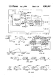
- FIG. 18 is an electric circuit diagram for illustrating a preferred embodiment of battery charging current control system in accordance with the present invention.
- FIG. 19 shows an exemplary current pulse waveform which may correspond with a maximum battery charging rate in a substantially linear operating range for an exemplary control system in accordance with FIG. 18;
- FIG. 20A shows selected control pulses which may be generated during control of battery charging current in the control system of FIG. 18, and FIG. 20B shows respective corresponding battery charging current pulses on the same time scale with vertically aligned portions of the waveforms of FIGS. 20A and 20B occurring at the same time;
- FIG. 21 is a diagrammatic view of use in explaining the aliased sampling of actual current pulses in the battery charging circuit, and illustrating the case where thirty-two samples form a complete sampling cycle;
- FIG. 22 is a block diagram for illustrating exemplary sampling circuitry for association with the V sense input of the processor means of FIG. 18;
- FIG. 23 illustrates a battery conditioning system as described at col. 17, lines 51-68 of the incorporated U.S. Pat. No. 4,455,523, and wherein two-way communication may be established between memory means associated with a portable unit comprised of rechargeable battery means, and a non-portable central computer controlled conditioning station;
- FIG. 24 shows a battery conditioning system wherein a battery identifying circuit element directly controls the set point of a battery charging circuit to determine a battery charging parameter, e.g., battery charging current;
- FIG. 25 shows a highly integrated semiconductor device, e.g. for implementing the system of FIGS. 18-22;
- FIG. 26 is an electric circuit block diagram showing a battery conditioning system wherein a preferred hand-held terminal unit contains battery parameter sensing means and computer operating means for optimizing battery charging current as supplied by an external circuit (which may correspond with a standardized circuit such a shown in FIG. 24 applicable to a complte family of hand-held terminals); and
- FIG. 27 shows a new RF terminal unit including charge control and temperature transducer outputs as in FIG. 26, and also incorporating an interface for coupling with a local area network so as to enable batch transmission of data to and from the RF terminal.
- FIGS. 1 through 17 The detailed description of FIGS. 1 through 17 is incorporated herein by reference to the specification at col. 4, line 25, through col. 66, line 4, of the incorporated U.S. Pat. No. 4,709,202.
- FIG. 18 shows processor means such as an integrated circuit microprocessor 18-10 which may form part of a circuit package of a battery pack 18-12.
- the circuit package may be secured with a rechargeable battery means 18-20, an association of such parts being shown in detail in FIGS. 2, 3 and 4.
- a battery charging means such as 12-24, FIG. 12, may provide a charging potential to a hand held computer unit such as 71, FIG. 5, and the unit 71 may supply an operating voltage +V to microprocessor 18-10 and may supply a charging potential +CHG to a series circuit including a current switch or current regulator means 18-22, an energy storage inductor means 18-24, battery means 18-20, and a current sense resistor 18-26.
- the processor means 18-10 may supply to line 18-27 rectangular pulses of a voltage waveform Vsw as shown in FIG. 20A.
- the duration or active duty cycle of the voltage pulses of waveform Vsw is modulated in discrete modulation steps to vary the turn-on time of switch means 18-22, and thus to vary battery charging current.
- battery means 18-20 may have battery charging parameter sensing means associated therewith as indicated at 18-28.
- Such parameter sensing means may have a battery temperature sensing transducer 18-30 corresponding to transducer 134, FIG. 9-A, and transducer 18-30 may be physically disposed in heat transfer relation to battery pack 18-12 as indicated in FIG. 18.
- processor means 18-10 may be controlled by a constant frequency means such as crystal 18-32.
- the clock rate of crystal 18-32 may be used to synchronize turn on of switch means 18-22 so that active duty cycles are initiated at a uniform time interval of less than one microsecond and may provide a desired number of modulation steps for the active duty cycle of the turn-on waveform Vsw.
- the operating frequency of crystal 18-32 may be six megahertz (i.e. thirty-two times a duty cycle frequency of 187.5 kilohertz) and may provide a time interval between activations of switch means 18-22 of 5.3333 microseconds with each such time interval being subdivided into thirty-two modulation steps.
- a moderate operating frequency of crystal 18-32 is favorable for a control system with low energy consumption, and an economical processor means.
- the turn-on time of switch means 18-22 may have different possible time durations per cycle corresponding to respective different numbers of the thirty-two modulation steps.
- the modulation steps may represent increments of 166.7 nanoseconds in the time duration of the active duty cycle of the waveform Vsw at line 18-27.
- maximum current flow an inductor 18-24 may correspond with a turn-on time corresponding to at least sixty percent of the maximum available on-time of switch means 18-22.
- current flow may increase relatively linearly as represented in FIG. 19 by sloping line 19-1 for numbers of time increments between zero and twenty or more.
- the circuit 18 includes means such as diode 18-36 for maintaining current flow when switch means 18-22 is turned off, the circuit preferably providing a current decay characteristic generally as indicated at 19-2 in FIG. 19.
- the current may decay to zero in less than one-half of the turn-on time of switch means 18-22, for the case of active duty cycles which provide a linear characteristic such as 19-1.
- the peak value 19-3 in FIG. 19 corresponds to twenty time increments or 3.33 microseconds (20 times 166.7 nanoseconds equals 3.33 microseconds)
- the decay interval may be less than ten increments, i.e. less than 1.67 microseconds.
- FIG. 20B shows the corresponding current flow in inductance 18-24, designated I(L) and the corresponding battery charging current I(CHG).
- the rising current characteristics 20-1 to 20-4 are linear where the number of increments is less than the number corresponding to peak 19-3 in FIG. 19.
- current sense resistance 18-26 is of a value much less than the resistance of battery means 18-20; for example, resistance means 18-26 may have a resistance value of 0.1 ohm.
- FIG. 20B thus also represents the waveform Vsense supplied at line 18-38 of FIG. 18, for the respective durations of Vsw of FIG. 20A.
- the processor means 18-10 includes analog to digital converter channels such as that associated with resistor 135, FIG. 9A, so that the battery temperature analog signal at 18-40 and the battery current analog signal at 18-38 may be converted into corresponding digital values.
- waveforms such as those represented in FIG. 20B would normally be sampled at a relatively high rate in comparison with the operating frequency of component 18-32
- the sampling rate of the pulsating analog waveform at line 18-38 is made lower than the rate of component 18-32 and preferably less than the active duty cycle frequency of waveform Vsw.
- the analog to digital converter means of processor 18-10 preferably deliberately under samples the current sense line 18-38 to alias the charging current waveform I(CHG) to a very low frequency.
- sampling may take place roughly at a frame sampling rate of 1/64 Fsw or roughly 2929 hertz.
- the actual aliasing sampling rate is not precisely synchronized with the switch activation rate Fsw, but differs slightly therefrom, for example, by one time increment or duty cycle modulation step of waveform Vsw, e.g. by a time increment of 166.7 nanoseconds per frame interval.
- one complete scan of the pulse configuration of the Vsense waveform at line 18-38 would take place for each 2049 Vsw pulses.
- the resultant sample waveform for a complete sampling cycle is diagrammatically indicated in FIG. 21 for the example of sampling as represented in FIGS. 20A and 20B.
- the frame sampling rate for the Vsense waveform on line 18-38 is roughly 1/256 Fsw, or about 732.42 hertz, then with one time increment of 167 nanoseconds added for each sampling frame, an actual sampling frequency of about 732.33 hertz results corresponding to 1.3655 milliseconds per sample. If thirty-two sample points of the Vsense waveform are scanned per complete sampling cycle, then one complete sampling cycle corresponds to 0.043696 second, or a frequency of 22.88 hertz.
- a corresponding average current value can be computed, by adding the most recent sample value (e.g., at ns33, FIG. 21) and subtracting the oldest sample value (e.g. sample ns1, FIG. 21), so that a new average current would be calculated at each 1.3655 milliseconds for the case of a sampling frequency of about 732.33 hertz.
- a sample and hold circuit may retain the sampled value of Vsense during the analog to digital conversion process.
- the preferred embodiment with an aliased sampling rate is considered applicable to current measurements where changes in the current waveform pulses are relatively slow, e.g. slower than the rate of change shown in FIG. 20B, where the alternating polarity component of the Vsense voltage averages out over a complete sampling cycle, and where the need for dynamic regulation of the current I(L) is minimal, i.e. the average direct current level per complete sampling cycle is the critical value to be regulated.
- the slow rate aliasing type of sampling is useful to adapt the sampling frequency to that feasible with an economical and simple processing means 18-10 (e.g. a type 8048 microprocessor).
- Other schemes to scan the Vsense signal could both skip frames and slip sample points, e.g.
- processor 18-10 may read battery temperature via input 18-40 at ten second intervals, and adjust the charging current set point value accordingly at each ten second reading of temperature.
- a noise filter in the form of a digital algorithm may insure that the actual digital current readings based on Vsense are free of disruptive noise.
- the active duty cycles of Vsw may be set to zero; for temperatures between minus twenty degrees Celsius and minus ten degrees Celsius (+14° F.), the charging current may be set to about C/20 (resulting in an average of about eight modulation increments for each active duty cycle of Vsw); for temperatures between minus ten degrees Celsius and zero degrees Celsius (32° F.), the charging current may be set to about C/16 (resulting in an average of about ten modulation increments for each active duty cycle of Vsw); for temperatures between zero degrees Celsius and ten degrees Celsius (50° F.), the charging current may be set to C/10 (to produce an average of about sixteen modulation increments for each active duty cycle of Fsw); for temperatures between ten degrees Celsius and seventy degrees Celsius (158° F.), the charging rate may be set to about C/8; above
- the programming of processor 18-10 may simply provide a table of numbers of modulation increments for the active duty cycle of Fsw according to respective ranges of measured temperature readings in digital form and the values of measured charging current may not enter into the selection of modulation increments.
- the sampling of charging current may be used for the fuel gauge function during normal operation of the hand held unit such as indicated at 10 in FIGS. 1 and 2, or in FIGS. 10, or at 12-10, FIG. 12.
- the circuitry of FIG. 18 may be permanently associated with the hand held device 10, rather than being a permanent part of the battery pack.
- the circuitry of FIG. 18 may be a permanent part of the battery pack along with a casing 60, FIG.
- the rechargeable battery means 18-20, FIG. 18, may be readily removable from casing 60 so as to be replaceable without replacement of components such as 18-10, 18-22, 18-24, 18-26, 18-28, 18-30, and 18-32.
- the transducer 18-30 need not be in physical proximity with the battery means 18-20.
- the processor 18-10 and switch means 18-22 can be part of the same silicon chip, for example.
- sensing means 18-28 may also receive an analog measure of battery voltage as indicated by a V(BATT) input at 18-42 and/or an analog measure of input charging voltage V(+CHG) as indicated at 18-44, and supply such analog measures to an analog to digital channel of processor means 18-10.
- the processor 18-10 may load a number equal to the number of desired modulation increments for the active duty cycle of Vsw into a register, and apply a suitable turn on voltage to line 18-27 until a number of clock pulses of oscillator means 18-32 has been counted corresponding to the number selected.
- the voltage across current measuring resistor 18-26, FIG. 18, may be supplied via line 18-38 to a low offset voltage linear amplifier 22-10.
- the output signal at 22-12 from amplifier 22-10 and the analog signals of multiconductor line 18-40 are supplied to respective sample and hold circuits of component 22-14.
- Successive samples of the battery current measurement waveform such as indicated at ns1, ns2, ns3, ns4, . . . , ns32, ns33, . . . , FIG. 21, may be selected by means of microprocessor 22-16 which is controlled by clock 18-32.
- Each sample may be obtained over a sample interval which may be equal to the clock period interval of one-sixth microsecond, for example, and may be held until it is converted to digital form by component 22-18 and supplied to a register of microprocessor 22-16 e.g. via conductors of a data bus forming part of the interconnecting means 22-19.
- the other analog signals are similarly sampled and transmitted e.g. to respective further registers of microprocessor 22-16.
- the microprocessor 22-16 may be programmed to compute a new average battery charge rate with each sample of actual battery current after the first N samples.
- the microprocessor would also take account of any changes in battery temperature, for example. As a specific example, it may be desired to maintain a maximum battery charging rate consistent with assurance of prolonged battery life, e.g. avoiding an excessive overcharge rate as discussed in relation to FIG. 6.
- processor means 18-10 may include a stored look up table wherein for respective temperature ranges, respective different settings for the desired average battery charging current are entered.
- An exemplary table based on FIG. 6 is as follows:
- n 10
- switch means 18-22 would be turned on, and clock pulses of clock oscillator 18-32 would be counted until the number corresponding to the n value stored in the duty cycle register was reached. Switch means 18-22 would then be turned off.
- sampling would take place as shown in FIG. 21. After sample ns32, a value of actual charging current would be calculated. If for example, the average actual current were calculated at 0.10C, and the battery temperature remained in the same range of 76° F. to 98° F., there would be a zero error and the value of ten would remain in the duty cycle register.
- the microprocessor 22-16 may be programmed to sample battery current during deep discharge of the battery means and during portable operation to obtain a measure of remaining battery life which may be displayed by the portable unit. See for example, Tables A and B herein.
- FIGS. 18, 19, 20A, 20B, 21 and 22 include the following by way of example and not of limitation:
- Constant frequency duty cycle repetition rate for Vsw e.g. a fraction of the clock rate a component 18-32 corresponding to a desired number of modulation increments per cycle of Vsw.
- Vsense at 18-38 is measured via a low offset voltage linear amplifier, a sample and hold circuit, and an analog to digital converter, e.g. as indicated in FIG. 22.
- Processor 18-10 obtains a measure of battery current during both battery charging and battery discharging operations.
- Processor 18-10 selects the duty cycle of Vsw according to ambient temperature to prolong battery life and enhance reliability of the complete hand held unit.
- the illustrated embodiment exemplifies a method of operation in a battery charging system wherein current is intermittently supplied from a voltage source means, e.g. V(+CHG), FIG. 18, to a chargeable battery means 18-20 via an energy storage means, e.g. inductance 18-24.
- the circuit arrangement is such that battery charging current continues to flow from the energy storage means to the battery means, e.g. via diode 18-36, at each interruption of the current flow at current regulator means 18-22.
- the intermittent actuation of current regulating means 18-22 produces a fluctuating battery charging current such as represented in FIGS. 19 and 20B which fluctuates in each of the successive operating cycles.
- the sampling means of component 18-10 is operated in an aliased asynchronous manner relative to the operating cycles of the battery charging current waveform such that battery charging current is sampled at respective different sampling times e.g. ts1, ts2, ts3, . . . , FIG. 20B, in respective different operating cycles e.g. cycles S1, S65, S129, . . . FIG. 20A, over a certain aliased sampling time interval, e.g. as represented at ns1 to ns32, FIG. 21. Because of the clock rate of clock oscillator 18-32, FIG. 18, e.g. six megahertz, the waveform of each operating cycle such as shown in FIG.
- aliased sampling however, a given cycle of the battery charging current may not be sampled at all, and for example, as shown in FIG. 20B, sampling may take place at intervals of about sixty-four operating cycles but asynchronously to the repetition interval of the operating cycles, so that successive actual sampling intervals such as ts1, ts2, ts3, ts4, . . . , FIG. 20B, scan through the potential sampling points, in each of a succession of aliased sampling cycles, each such aliased sampling cycle having a duration, for example, greater than one millisecond (e.g. 43.696 milliseconds).
- a duration for example, greater than one millisecond (e.g. 43.696 milliseconds).
- the sample values can be added and an average obtained as a measure of average battery charging current.
- the earliest sample e.g. sample number one, can be discarded, and a new average value calculated.
- the battery or environmental sensing means 18-28 in conjunction with transducer 18-30 may measure an ambient temperature related to the temperature of the battery means 18-20 and determine an optimum battery charging rate based at least in part on the most recent measurement of battery temperature.
- the processor means 18-10 may be programmed to select a maximum battery charging rate consistent with assurance of prolonged battery life, e.g. avoiding an excessive overcharge rate as discussed in relation to FIG. 6.
- processor means 18-10 may include a stored look up table wherein for each respective temperature range of significance, respective different settings for the desired average battery charging current are entered.
- sampling may be effected at time intervals equal to about the fifth power of two (32) times the duration of an operating cycle, or about the tenth power of two (1024) times the duration of a discrete sampling interval.
- the potential discrete sampling intervals may have a duration of one-sixth microsecond (about 167 nanoseconds).
- the time between samples may be substantially longer than one microsecond, e.g. of the order of one-sixth of a millisecond.
- the operating frame period is itself greater than one microsecond (e.g. 5.33 microseconds).
- the energy in the inductance 18-24 may be essentially dissipated in less than ten microseconds, for example in a time interval of about one-third microsecond.
- FIG. 23 illustrates a non-portable system for inserting a measured value of battery capacity of a rechargeable battery means 23-20 into a memory of processor, memory and communications means 23-82 of the battery system indicated at 23-18, after each deep discharge cycle as effected by deep discharge controller 23-110.
- the deep discharge cycle of controller 23-110 and the charging cycle of charging controller 23-101 may be controlled by a separate non-portable computer system 23-71 at a central charging station.
- This computer system may be capable of communication with the memory of means 23-82 of the battery system via communications interface means 23-51A for inserting an accurate actual measurement of battery capacity.
- the central computer of non-portable computer system 23-71 may interrogate the memory of means 23-82 for relevant battery history and then selectively determine a suitable charging voltage and charging current at charging interface means 23-51B.
- the memory of component 23-82 may contain a non-volatile read only memory which identifies the particular associated battery pack as to its capacity, rated voltage and other characteristics relevant to conditioning operations.
- the central charging station may interrogate the different battery packs coupled therewith and select charging and deep discharge cycle parameters according to the individual characteristics of the respective different battery packs.
- FIG. 23 may correspond with components of FIG. 5 as follows:
- Components 23-71, 23-101, 23-103, and 23-110 may be analogous to components 71, 101, 103 and 110 in FIG. 5.
- Interface means 23-51A and 23-51B may be analogous to interface or connector means 51, FIG. 5.
- FIG. 24 shows a battery conditioning circuit which may be utilized in place of the central computer controlled charging station of FIG. 23.
- the system of FIG. 24 may have a receiving device for a hand-held unit as described in Chadima et al U.S. Pat. No. 3,823,388 (e.g. in reference to the fifth figure thereof at col. 9, lines 20-31). See also a brochure of Norand Corporation entitled “Route Commander" Portable Data System for bakery distribution, No. 960-382-0884, copyright 1984, a copy of two sections thereof being included in Appendix A hereto.
- FIG. 24 When a hand-held device indicated at 24-10, FIG. 24, (such as shown in incorporated FIG. 1) is inserted into its receptacle, its charge input indicated at 24-11 is coupled with contact 24-12A, FIG. 24, of the CHARGE output line 24-12, and a further terminal contact 24-13 is coupled with contact 24-14A of the CHG CONTROL line 24-14.
- the receptacle may receive different hand-held terminals with different battery configurations, and each configuration would provide a characteristic resistance value between the terminal ground contact such as 24-15 (connected with ground contact 24-16A of GND line 24-16) and the terminal charge control contact such as 24-13.
- the terminal resistance value is thus connected between contact 24-14A and the ground contact 24-16A, and in parallel with a resistor 24-R1 of a charge control reference network 24-20 which further includes resistors 24-R2, 24-R3 and zener 24-Z1.
- the network receives an activating potential from a charging supply input line 24-21 (+12 V) via a charging supply potential responsive line 24-21A which is connected between a resistor 24-R4 and a zener 24-Z2.
- the current flow path between the charging supply input line 24-21 and CHARGE output line 24-12 includes a charge current sensing resistor 24-R5 and a charge current regulating transistor 24-Q1.
- the value of charge current is controlled by means of a control circuit 24-22 which includes linear operational amplifiers 24-U1, 24-U2 and 24-U3, transistors 24-Q2 and 24-Q3, resistors 24-R6 through 24-R17, and capacitors 24-C1 and 24-C2.
- the linear operational amplifiers may receive a supply voltage of plus twelve volts (+12 V) relative to ground potential from supply input 24-21, and may be of type LM2902.
- the charging current supplied by the circuit of FIG. 24 will increase for increasing potentials at control point 24-23 up to the limit potential of zener 24-Z1 (which may for example be 1.25 volts).
- the limit potential for zener Z4-Z2 is 2.50 volts
- the maximum potential at circuit point 24-24 may be designated VR1 with an open circuit between contacts 24-14A and 24-16A. This potential VR1 is then progressively reduced for respective terminal resistance values between about three times the value of 24-R1 (e.g. 5.62 kilohms plus or minus one percent) and about one-third the value of 24-R1, for example.
- Exemplary circuit parameters for FIG. 24 are as follows (the letter K standing for kilohms):
- respective different terminals 24-10 (such as terminal 10 of incorporated FIG. 1), having respective different charging current requirements are provided with respective corresponding ohmic resistance values between their contacts such as indicated at 24-13 and 24-15, FIG. 24.
- each respective different terminal 24-10 will automatically produce the respective required charging current by virtue of the action of control circuit 24-22.
- the potential at 24-24, FIG. 24 may be coupled with a central computer system such as 23-71 via an analog to digital converter so as to identify the type of battery means to the central computer.
- the resistance between terminals 24-13 and 24-15 would normally be a resistor such as indicated at 24-26 fixedly associated with the battery means such as indicated at 24-27, so that replacing a battery means in a given terminal with a battery means of different ampere-hour capacity would automatically change the resistance value engaged with terminal contacts 24-13, 24-15.
- the computer system 23-71 of FIG. 23 in this modification would thus receive an identification of battery capacity along with other battery parameters, and control battery conditioning (e.g. deep discharge) according to relevant parameters including battery capacity, while battery charging would be automatically controlled by a circuit such as shown in FIG. 24.
- component 25-10 is a custom control chip for integrating the functions of components 18-10 and 18-28, FIG. 18, into a single monolithic semiconductor element.
- the external path for supplying charging current to battery 25-20 includes transistor 25-22, inductor 25-24 and charging current sensing resistor 25-26 which may correspond with components 18-22, 18-24 and 18-26, FIG. 18.
- a pulse width modulated output corresponding to that shown in FIG. 20A, is supplied at VS output 25-27 of chip 25-10 for controlling the on-time of transistor 25-28 which in turn controls the switching action of transistor 25-22.
- Components 25-30, 25-32 and 25-36 may essentially correspond with components 18-30, 18-32 and 18-36 in FIG. 18.
- Charging current sensing input 25-38 may correspond with input 18-38, FIGS. 18-22, and may control circuitry of chip 25-10 such as represented by components 22-10, 22-14, 22-16 and 22-18, FIG. 22.
- the chip 25-10 is shown as sensing battery voltage (+BATT) via a line 25-42 and a first resistance voltage divider 25-43A, 25-43B, and is shown as sensing charging input potential (+CHG) via a line 25-44 and a second resistance voltage divider 25-45A, 25-45B.
- VCC Operating potential is supplied to chip 25-10 from charging input potential (+CHG) via a voltage regulator 25-46.
- Data communications e.g. between chip 25-10 and a central computer system such as 23-71, FIG. 23, may take place via stage 25-50 for data reception (BPWDATA) and via stage 25-51 for data transmission (BPRDATA).
- BPWDATA data reception
- BPRDATA data transmission
- Chip 25-10 may control battery discharge conditioning via transistor 25-60.
- FIG. 25 The operation of FIG. 25 will be apparent from a consideration of the preceding Description of FIGS. 18, 19, 20A, 20B, 21 and 22.
- FIG. 26 shows a preferred form of hand-held terminal unit 26-10 which may be associated with an external conditioning circuit such as shown in FIG. 24 by means of respective sets of mating contacts 26-11, 26-12A; 26-13, 26-14A; 26-15, 26-16A; in the same way as described for FIG. 24.
- Charging current is supplied to terminal unit 26-19 via CHARGE line 26-12, and an analog charge rate control signal may be applied from terminal unit 26-10 to CHG Control line 26-14, while terminal ground is connected with GND line 26-16 of the conditioning station.
- a charge control reference network 26-20 may comprise a resistance network 26-R1, 26-R2 and 26-R3 and a zener 26-Z1 for receiving activating potential from a charging supply input line 26-21 (+12 V) via a charging supply potential responsive line 26-21A.
- a charging current control circuit 26-22 may correspond with that of FIG. 24 and controls the charging current supplied via line 26-12 in accordance with a control signal potential at 26-23.
- resistance network 26-20 serves as a control signal generating network which provides a default value of control signal at circuit point 26-23 in the absence of any modifying input from a hand-held terminal unit.
- older model terminal units may present an open circuit to station contacts 24-14A, 24-16A or 26-14A, 26-16A, and the generating network 24-20 or 26-20 by itself may provide a default value of control signal which results in the supply of a generally suitable value of charging current at 24-12 or 26-12, say 130 milliamperes.
- the potential at circuit point 26-24 may be modified from the default value according to information and programming carried by the terminal unit, for example to produce a rapid charge rate, a moderate charge rate or a maintenance charge rate in dependence on the battery parameters of the terminal battery means 26-27, ideally so that an optimum charging rate is selected.
- Such charging rate can in principle take account of the load to be presented to the charging circuit by components of the terminal unit which will be functioning during the charging operation, e.g. terminal circuits for effecting a downloading of data from the memory of the terminal unit.
- the charging current path in FIG. 26 may include an optional current regulator 26-28 which is part of the portable terminal unit.
- the current regulator 26-28 could be present in cases where the terminal might be charged by means of a charging circuit without the current control features of circuit 26-22.
- current regulator 26-28 it is preferred that current regulator 26-28 be unnecessary, (because of the use of a charger configuration such as shown in FIGS. 24 and 26) and therefore preferably current regulator 26-28 is omitted, and line 26-33 is directly connected with contact 26-11.
- the negative terminal of the battery means is preferably returned directly to ground potential as indicated at 26-30, without the presence of a current sensing resistor such as indicated at 25-26, FIG. 25.
- current sense resistor 24-30, FIG. 24 may be short circuited, particularly where the terminal processor means is programmed to accumulate a measure of battery usage. Omission of a current sense resistor such as 24-30 is particularly advantageous where the battery is to supply relatively high peak current as in portable radio frequency (RF) terminals which communicate data on line to a base computer station an RF link.
- RF radio frequency
- battery parameter sensing means are illustrated, comprised of a temperature transducer 26-32 for obtaining a measure of battery temperature, and a battery potential sensing line 26-33 for sensing battery terminal voltage.
- components 26-34, 26-35, 26-36 and 26-37 may be on a single semiconductor chip with processor, timing and memory means 26-40 of the portable unit.
- Components 26-35 and 26-36 correspond with components 22-14 and 22-18 of FIG. 22 and comprise battery parameter input means for supplying measures of battery temperature and battery terminal voltage e.g. in binary digital format to the processor and memory components.
- Component 26-40 may include the clock-controlled microprocessor corresponding to 22-16, FIG. 22, and the interconnections of FIG. 22 have been omitted in FIG. 26 for simplicity of illustration.
- temperature transducer 26-32 may have its signal coupled to a further contact 26-50 via a line 26-51.
- the control circuit 26-22 can itself adjust charging current according to battery temperature.
- the presence of a nonzero potential at line 26-51 may indicate that operating potential has been applied to transducer 26-32 from a charger circuit. (See e.g. the specific circuit of FIG. 27.)
- FIG. 27 illustrates a new RF terminal unit which may be associated with a non-portable battery conditioning system in a similar way as FIG. 26.
- FIG. 27 diagrammatically illustrates an RF terminal system 27-10A which removeably receives a rechargeable battery pack 27-10B.
- the rechargeable batteries may be contained in a removeable drawer as illustrated in pending application of George E. Chadima, Jr., et al, U.S. Ser. No. 104,653 filed Oct. 2, 1987, and entitled “HAND-HELD COMPUTER SYSTEM", and this disclosure is incorporated herein by reference in its entirety.
- an end cap of the RF terminal unit may be provided with conventional contactors such as indicated at 27-11, 27-13, 27-15, 27-17, 27-19 and 27-21, which provide for quick connection with the battery pack and terminal circuitry simply by placing the terminal assembly into a suitable receptacle, for example, in a delivery vehicle or the like.
- the delivery vehicle may be provided with a charger circuit such as indicated at 27-22 which may be provided with a conventional terminal unit receptacle similar to that shown in page A2 of Appendix A hereto, which receptacle is provided with contacts for quick release engagement with the terminal contacts 27-11 etc.
- the battery pack may be provided with a rechargeable battery 27-27 and a temperature transducer 27-32, e.g.
- the terminal assembly designated generally 27-10 further is indicated as including a resistor 27-R1 and a diode 27-D1 in the battery pack and a corresponding resistor 27-R2 and a corresponding diode 27-D2 in the terminal itself. It will be noted that the potential across transducer 27-32 will be zero until such time as a charge potential is applied at contact 27-11, so that the presence of a potential different from zero volts at contact 27-17 and at line 27-33 will indicate application of charging potential to the assembly 27-10.
- the circuitry at 27-35A and 27-35B in FIG. 27 may correspond with the circuitry 26-34 and 26-35 in FIG.
- 26 may represent a suitable commercially available integrated circuit for sensing analog values of battery terminal voltage and temperature, and for supplying corresponding digital values to a terminal processor such as indicated at 26-40 in FIG. 26.
- Component 27-37 in FIG. 27 may correspond with components 26-36 and 26-37 in FIG. 26 and may receive an output control word from a processor corresponding to 26-40 in FIG. 26 for establishing a desired control signal potential at contact 27-13 as described in detail with reference to FIG. 26.
- the processor circuit of FIG. 27 may be provided with a local area network (LAN) interface 27-39 for communication with exterior devices via contacts 27-19 and 27-21, for example.
- LAN local area network
- the terminal 27-10A is not only provided with RF circuitry and antenna means for on-line data interchange with a RF base station, but further the plug-in contacting of the terminal body at 27-19 and 27-21 provides for batch type transmission between the terminal 27-10 and an exterior station, permitting the batch type downloading of data, for example programming, into the terminal 27-10, and the batch type uploading of stored data from the terminal to an external station, for example a printer of a vehicle such as previously mentioned.
- the incorporated patent application Ser. No. 104,653 shows in the tenth figure a fifteen pin "D" subminiature connector. Certain pins of this connector are indicated at 27-47 through 27-52 in FIG. 27, so that the terminal 27-10 can be coupled by means of such connector with a charger circuit such as indicated at 27-60, for example by means of a suitable connecting cable or the like.
- the charger circuit 27-60 may correspond with the charger circuit of FIG. 24 or FIG. 26, for example, and may include components connected to the local area network interface 27-39 via contacts 27-51 and 27-52.
- the local area network interface 27-39 may be utilized to transmit to the charger 27-22 or 27-60 battery information such as rated battery capacity and hours of use subsequent to a previous charge as explained in detail with respect to FIGS. 23 and 26.
- the processor of components 23-27, 25-10, 26-40 or of FIG. 27 can be programmed with a schedule of battery charging currents as a function of temperature such as described with reference to FIGS. 18-22.
- a schedule of battery charging currents as a function of temperature such as described with reference to FIGS. 18-22.
- the charging rate can be adjusted according to a quantitative measure of battery temperature so as to achieve a maximum charging rate consistent with the specific characteristics of the battery means 23-20, 25-20, 26-27 or 27-27.
- abnormally high or low values may represent a defective battery or short circuit, so that the processor of component 23-71, 25-10, 26-40, or of FIG. 27 would be programmed to provide a shutoff control potential for the charging circuit.
- a maximum potential from the converter channel 26-37 could establish a control potential at circuit point 26-23 of 1.25 volts, the limit potential of zener 26-Z1, and produce zero charging current (corresponding to a shut-off of transistor 24-Q1, FIG. 24).
- FIG. 26, or of FIG. 27 keeps track of usage of the hand-held terminal unit in the portable (off the charger) mode
- the accumulated hours of use along with rated battery capacity can be transmitted to the central computer system 23-71 at the start of a conditioning operation, or can be utilized in selecting a suitable computer generated control word for register 26-36 in FIG. 26 or for component 27-37, FIG. 27.
- the processor e.g. of 26-40 may increment an elapsed time counter (e.g.
- each portable terminal unit may store battery information such as indicated in TABLE B of incorporated U.S. Pat. No.4,553,081 (col. 14, line 40-col. 15, line 58), and battery information may be transmitted to an external processor e.g. of component 23-71, FIG. 23, when the terminal unit is plugged into a conditioning station preparatory to conditioning operation, and in any case the stored data may be used as battery information in the generation of charging current control signals, e.g. in the embodiments of FIGS. 23, 25, 26 and 27.
- battery information such as indicated in TABLE B of incorporated U.S. Pat. No.4,553,081 (col. 14, line 40-col. 15, line 58)
- battery information may be transmitted to an external processor e.g. of component 23-71, FIG. 23, when the terminal unit is plugged into a conditioning station preparatory to conditioning operation, and in any case the stored data may be used as battery information in the generation of charging current control signals, e.g. in the embodiments of FIGS. 23, 25, 26 and 27
- communication between a processor, e.g. of components 18-10, 23-82, 25-10, 26-40, or of FIG. 27, and an external station may include the types of commands given in TABLE A of incorporated patent 4,553,081 (col. 14, lines 14-39).
- FIGS. 1-12 flowcharts, timing diagrams and an exemplary lookup table, suitable for the processor of a portable terminal unit such as processor 14 of FIGS. 1-12, or of 18-10, FIG. 18, or of 26-40, FIG. 26, or of FIG. 27, and also suitable for a central processor such a 23-71, FIG. 23, are shown in APPENDIX B hereto (pages B1 to B10 following the ABSTRACT OF THE DISCLOSURE). This information was generated for the battery processor 140, FIG. 9B, but was not originally included since it was not considered to be required for practicing this mode of the invention.
- FIGS. 18-22 or 25 may form a part of a stationary battery charging system which removably receives spare battery packs, and/or which removably receives hand-held units such as shown in FIG. 1.
- the processor means 18-10 or 25-10 as the main processor of a hand-held terminal unit may measure actual battery discharge current during use of the hand-held unit and then control the duration of recharging according to such measure, and/or according to rated battery capacity as stored in a read only memory of the main processor, or the like.
- Many further modifications and variations will readily occur to those skilled in the art from a consideration of the teachings and concepts of the present disclosure.
Abstract
Description
______________________________________
Exemplary Table Of Desired
Average Battery Charging
Current As A Function Of
Temperature (See FIG. 6.)
                          Corresponding
Temperature  Average Battery
                          Nominal
Range (°F.)
             Charging Current
                          n Value
______________________________________
Below 2.5    Zero         0
2.5 to 35    C/100        1
35 to 76     C/20         5
76 to 98     C/10         10
98 to 112.5  C/6.7        15
Over 112.5   Zero         0
______________________________________
______________________________________
Component         Corresponding Component
of FIG. 23        or Components of FIG. 5
______________________________________
Battery System 23-18
                  Components 20, 81-83,
                  and 91-93
Rechargeable Battery
                  Rechargeable Battery
Mean 23-20        Means 20
Memory and        Battery Processor, Timing
Communications Means
                  and Memory Circuits 82,
23-82             Digital Interface 81 and
                  Voltage Regulator and
                  Reset Component 83
Battery Voltage   Component 91
Monitor 23-91
Battery Current   Component 92
Monitor 23-92
Battery Temperature
                  Component 93
Monitor 23-93
______________________________________
______________________________________
Exemplary Circuit
Parameters, FIG. 24
______________________________________
24-U1, 24-U2, 24-U3   Type LM2902
24-Q1                 power transistor
24-Q2, 24-Q3          Type 2N3904
24-R1                 5.62 K (1%)
24-R2                 100 K (1%)
24-R3                 10 K
24-R4                 4.7 K
24-R5                 one ohm (1%)
24-R6                 one kilohm (1 K)
24-R7, 24-R8, 24-R9, 24-R10
                      10 K (.1%)
24-R11, 24-R12        10 K
24-R13, 24-R14        one kilohm (1 K)
24-R15                820 ohms
24-R16                30.1 K (1%)
24-R17                10 K (1%)
24-C1, 24-C2          .1 microfarad
24-Z1                 LM385BZ (1.25 volts)
24-Z2                 LM385BZ (2.50 volts)
______________________________________
Claims (25)
Priority Applications (17)
| Application Number | Priority Date | Filing Date | Title |
|---|---|---|---|
| US07/422,226 US4961043A (en) | 1988-03-15 | 1989-10-16 | Battery conditioning system having communication with battery parameter memory means in conjunction with battery conditioning |
| US07/769,337 US5278487A (en) | 1988-03-15 | 1991-10-01 | Battery conditioning system having communication with battery parameter memory means in conjunction with battery conditioning |
| US07/837,650 US5463305A (en) | 1982-06-07 | 1992-02-18 | Fast battery charging system and method |
| US07/957,470 US5493199A (en) | 1982-06-07 | 1992-10-06 | Fast battery charger |
| US08/134,881 US5508599A (en) | 1988-03-15 | 1993-10-12 | Battery conditioning system having communication with battery parameter memory means in conjunction with battery conditioning |
| US08/315,825 US5856737A (en) | 1982-06-07 | 1994-09-30 | Fast battery charging system and method |
| US08/399,742 US5696435A (en) | 1982-06-07 | 1995-03-07 | Fast battery charger for a device having a varying electrical load during recharging |
| US08/415,075 US5619117A (en) | 1982-06-07 | 1995-03-30 | Battery pack having memory |
| US08/841,975 US5883492A (en) | 1982-06-07 | 1997-04-08 | Battery pack having memory |
| US08/841,974 US5883493A (en) | 1982-06-07 | 1997-04-08 | Battery pack having memory |
| US09/082,061 US5889386A (en) | 1982-06-07 | 1998-05-20 | Battery conditioning system having communication with battery parameter memory means in conjunction with battery conditioning |
| US09/205,518 US5986435A (en) | 1982-06-07 | 1998-12-03 | Method of utilizing a battery powered system having two processors |
| US09/223,983 US6043630A (en) | 1982-06-07 | 1999-01-04 | Fast battery charging system and method |
| US09/270,302 US6075340A (en) | 1985-11-12 | 1999-03-15 | Battery pack having memory |
| US09/513,290 US6271643B1 (en) | 1986-12-18 | 2000-02-24 | Battery pack having memory |
| US09/513,216 US6252380B1 (en) | 1984-05-21 | 2000-02-24 | Battery pack having memory |
| US09/855,748 US20020101218A1 (en) | 1984-05-21 | 2001-05-14 | Battery pack having memory |
Applications Claiming Priority (2)
| Application Number | Priority Date | Filing Date | Title |
|---|---|---|---|
| US07/168,352 US4885523A (en) | 1988-03-15 | 1988-03-15 | Battery conditioning system having communication with battery parameter memory means in conjunction with battery conditioning |
| US07/422,226 US4961043A (en) | 1988-03-15 | 1989-10-16 | Battery conditioning system having communication with battery parameter memory means in conjunction with battery conditioning |
Related Parent Applications (7)
| Application Number | Title | Priority Date | Filing Date |
|---|---|---|---|
| US07/168,352 Division US4885523A (en) | 1982-06-07 | 1988-03-15 | Battery conditioning system having communication with battery parameter memory means in conjunction with battery conditioning |
| US07/168,352 Continuation-In-Part US4885523A (en) | 1982-06-07 | 1988-03-15 | Battery conditioning system having communication with battery parameter memory means in conjunction with battery conditioning |
| US07/226,537 Continuation-In-Part US4863368A (en) | 1987-07-30 | 1988-07-29 | Injection molding machine for a selective linear or central charging of mold assemblies |
| US26653788A Continuation-In-Part | 1982-06-07 | 1988-11-02 | |
| US07/422,226 Continuation-In-Part US4961043A (en) | 1982-06-07 | 1989-10-16 | Battery conditioning system having communication with battery parameter memory means in conjunction with battery conditioning |
| US44623189A Continuation-In-Part | 1982-06-07 | 1989-12-05 | |
| US09/513,290 Division US6271643B1 (en) | 1986-12-18 | 2000-02-24 | Battery pack having memory |
Related Child Applications (6)
| Application Number | Title | Priority Date | Filing Date |
|---|---|---|---|
| US26653788A Continuation-In-Part | 1982-06-07 | 1988-11-02 | |
| US07/422,226 Continuation-In-Part US4961043A (en) | 1982-06-07 | 1989-10-16 | Battery conditioning system having communication with battery parameter memory means in conjunction with battery conditioning |
| US44623189A Continuation-In-Part | 1982-06-07 | 1989-12-05 | |
| US47818090A Continuation-In-Part | 1982-06-07 | 1990-02-09 | |
| US54423090A Division | 1982-06-07 | 1990-06-26 | |
| US54423090A Continuation-In-Part | 1982-06-07 | 1990-06-26 |
Publications (1)
| Publication Number | Publication Date |
|---|---|
| US4961043A true US4961043A (en) | 1990-10-02 |
Family
ID=26864036
Family Applications (1)
| Application Number | Title | Priority Date | Filing Date |
|---|---|---|---|
| US07/422,226 Expired - Lifetime US4961043A (en) | 1982-06-07 | 1989-10-16 | Battery conditioning system having communication with battery parameter memory means in conjunction with battery conditioning |
Country Status (1)
| Country | Link |
|---|---|
| US (1) | US4961043A (en) |
Cited By (77)
| Publication number | Priority date | Publication date | Assignee | Title |
|---|---|---|---|---|
| WO1991000623A2 (en) * | 1989-06-30 | 1991-01-10 | Motorola, Inc. | Battery charging system |
| US5136231A (en) * | 1990-10-12 | 1992-08-04 | Compaq Computer Corporation | Ni-cad battery charge rate controller |
| US5200689A (en) * | 1992-01-24 | 1993-04-06 | Compaq Computer Corporation | Battery charge monitor to determine fast charge termination |
| GB2260231A (en) * | 1991-10-01 | 1993-04-07 | Apple Computer | Power management system for battery powered computers |
| US5218286A (en) * | 1991-09-16 | 1993-06-08 | Monarch Marking Systems, Inc. | Multichannel battery charger |
| US5250891A (en) * | 1991-05-13 | 1993-10-05 | Milwaukee Electric Tool Corporation | Battery charging method and apparatus |
| WO1994001913A1 (en) * | 1992-07-08 | 1994-01-20 | Benchmarq Microelectronics, Inc. | Method and apparatus for monitoring battery capacity under fast discharge conditions |
| US5284719A (en) * | 1992-07-08 | 1994-02-08 | Benchmarq Microelectronics, Inc. | Method and apparatus for monitoring battery capacity |
| US5304916A (en) * | 1990-04-11 | 1994-04-19 | Compaq Computer Corporation | Battery charger |
| US5307001A (en) * | 1992-05-05 | 1994-04-26 | Dimensions Unlimited, Inc. | Battery charging method and apparatus |
| US5315228A (en) * | 1992-01-24 | 1994-05-24 | Compaq Computer Corp. | Battery charge monitor and fuel gauge |
| US5345392A (en) * | 1991-01-25 | 1994-09-06 | International Business Machines Corporation | Battery charge monitor for a personal computer |
| US5349535A (en) * | 1992-10-20 | 1994-09-20 | Digicomp Research Corporation | Battery condition monitoring and recording system for electric vehicles |
| US5352969A (en) * | 1991-05-30 | 1994-10-04 | Black & Decker Inc. | Battery charging system having logarithmic analog-to-digital converter with automatic scaling of analog signal |
| US5355073A (en) * | 1992-09-30 | 1994-10-11 | Compaq Computer Corporation | Battery pack sensor for an AC adapter |
| US5363312A (en) * | 1990-03-30 | 1994-11-08 | Kabushiki Kaisha Toshiba | Method and apparatus for battery control |
| US5402055A (en) * | 1992-09-30 | 1995-03-28 | Compaq Computer Corporation | AC adapter including differential comparator for tracking battery voltage during trickle charge |
| US5426386A (en) * | 1992-04-21 | 1995-06-20 | Benchmarq Microelectronics, Inc. | Low-power semiconductor voltage comparator with hysteresis |
| US5432429A (en) | 1990-10-23 | 1995-07-11 | Benchmarq Microelectronics, Inc. | System for charging/monitoring batteries for a microprocessor based system |
| US5440221A (en) | 1992-07-08 | 1995-08-08 | Benchmarg Microelectronics, Inc. | Method and apparatus for monitoring batttery capacity with charge control |
| US5508599A (en) * | 1988-03-15 | 1996-04-16 | Norand Corp. | Battery conditioning system having communication with battery parameter memory means in conjunction with battery conditioning |
| US5514946A (en) * | 1993-03-19 | 1996-05-07 | Compaq Computer Corp. | Battery pack including static memory and a timer for charge management |
| US5515087A (en) * | 1993-12-02 | 1996-05-07 | Hewlett-Packard Company | Remaining battery capacity determination method and apparatus |
| US5539298A (en) * | 1993-03-19 | 1996-07-23 | Compaq Computer Corporation | Pulse charge technique to trickle charge a rechargeable battery |
| US5600566A (en) * | 1994-02-28 | 1997-02-04 | Samsung Heavy Industries Co., Ltd. | Apparatus and method for monitoring state of battery |
| US5606242A (en) * | 1994-10-04 | 1997-02-25 | Duracell, Inc. | Smart battery algorithm for reporting battery parameters to an external device |
| US5608306A (en) * | 1994-03-15 | 1997-03-04 | Ericsson Inc. | Rechargeable battery pack with identification circuit, real time clock and authentication capability |
| US5633573A (en) * | 1994-11-10 | 1997-05-27 | Duracell, Inc. | Battery pack having a processor controlled battery operating system |
| US5686815A (en) * | 1991-02-14 | 1997-11-11 | Chartec Laboratories A/S | Method and apparatus for controlling the charging of a rechargeable battery to ensure that full charge is achieved without damaging the battery |
| EP0655172B1 (en) * | 1992-08-14 | 1998-01-07 | Chartec Laboratories A/S | Method for battery charging and a battery system |
| WO1998002933A1 (en) * | 1996-07-17 | 1998-01-22 | Duracell Inc. | Battery operating system |
| US5717256A (en) * | 1994-06-08 | 1998-02-10 | Fujitsu Limited | Power supply apparatus and electronic appliance equipped with the power supply apparatus |
| US5883493A (en) * | 1982-06-07 | 1999-03-16 | Intermec Technologies Corporation | Battery pack having memory |
| US5929764A (en) * | 1995-05-16 | 1999-07-27 | Hewlett-Packard Company | Battery powered electronic device for exchanging information with a battery mailbox |
| US5952815A (en) * | 1997-07-25 | 1999-09-14 | Minnesota Mining & Manufacturing Co. | Equalizer system and method for series connected energy storing devices |
| US5986435A (en) * | 1982-06-07 | 1999-11-16 | Intermec Ip Corp. | Method of utilizing a battery powered system having two processors |
| US6025695A (en) * | 1997-07-09 | 2000-02-15 | Friel; Daniel D. | Battery operating system |
| US6031359A (en) * | 1996-10-10 | 2000-02-29 | Chartec Laboratories A/S | Digitally controlled switch mode power supply for charging rechargeable batteries |
| US6046514A (en) * | 1997-07-25 | 2000-04-04 | 3M Innovative Properties Company | Bypass apparatus and method for series connected energy storage devices |
| US6075340A (en) * | 1985-11-12 | 2000-06-13 | Intermec Ip Corp. | Battery pack having memory |
| US6075339A (en) * | 1993-08-16 | 2000-06-13 | Chartec Laboratories A/S | Battery system providing indicia of a charging parameter |
| US6087036A (en) * | 1997-07-25 | 2000-07-11 | 3M Innovative Properties Company | Thermal management system and method for a solid-state energy storing device |
| US6100702A (en) * | 1997-07-25 | 2000-08-08 | 3M Innovative Properties Company | In-situ fault detection apparatus and method for an encased energy storing device |
| US6099986A (en) * | 1997-07-25 | 2000-08-08 | 3M Innovative Properties Company | In-situ short circuit protection system and method for high-energy electrochemical cells |
| US6104967A (en) * | 1997-07-25 | 2000-08-15 | 3M Innovative Properties Company | Fault-tolerant battery system employing intra-battery network architecture |
| US6107802A (en) * | 1992-07-08 | 2000-08-22 | Matthews; Wallace Edward | Battery pack with monitoring function utilizing association with a battery charging system |
| US6117584A (en) * | 1997-07-25 | 2000-09-12 | 3M Innovative Properties Company | Thermal conductor for high-energy electrochemical cells |
| US6120930A (en) * | 1997-07-25 | 2000-09-19 | 3M Innovative Properties Corporation | Rechargeable thin-film electrochemical generator |
| US6218806B1 (en) | 1998-06-03 | 2001-04-17 | Black & Decker Inc. | Method and apparatus for obtaining product use information |
| US6235425B1 (en) | 1997-12-12 | 2001-05-22 | 3M Innovative Properties Company | Apparatus and method for treating a cathode material provided on a thin-film substrate |
| US6271643B1 (en) | 1986-12-18 | 2001-08-07 | Intermec Ip Corp. | Battery pack having memory |
| US6307349B1 (en) | 2000-02-24 | 2001-10-23 | Intermec Ip Corp. | Battery pack having memory |
| US6369576B1 (en) | 1992-07-08 | 2002-04-09 | Texas Instruments Incorporated | Battery pack with monitoring function for use in a battery charging system |
| US6377028B1 (en) | 1990-10-23 | 2002-04-23 | Texas Instruments Incorporated | System for charging monitoring batteries for a microprocessor based method |
| WO2002045238A2 (en) * | 2000-11-28 | 2002-06-06 | Telefonaktiebolaget L M Ericsson (Publ) | Life cycle charging for batteries |
| US20020156537A1 (en) * | 2001-04-18 | 2002-10-24 | Kazuyuki Sakakibara | Methods and apparatus for managing a plurality of charging devices via a network |
| US20030034757A1 (en) * | 2000-12-04 | 2003-02-20 | Woodnorth Douglas J. | Utilizing portable electrical power sources |
| US20030139888A1 (en) * | 2001-11-27 | 2003-07-24 | Burns Charles E. | Battery management system and method |
| US6641942B1 (en) | 1997-07-25 | 2003-11-04 | 3M Innovative Properties Company | Solid-state energy storage module employing integrated interconnect board |
| US20040002825A1 (en) * | 2002-06-27 | 2004-01-01 | Kurt Raichle | Apparatus and method for determining the temperature of a charging power source |
| US20040046026A1 (en) * | 2002-09-06 | 2004-03-11 | Scott Krampitz | Code reading apparatus and method |
| US20040090952A1 (en) * | 1990-01-18 | 2004-05-13 | Kubler Joseph J. | Hierarchical data collection network supporting packetized voice communications among wireless terminals and telephones |
| US20050184593A1 (en) * | 1994-03-03 | 2005-08-25 | American Power Conversion Corporation | Battery communication system |
| US20050261844A1 (en) * | 2004-05-21 | 2005-11-24 | Uwe-Jens Iwers | Method for planning the journey of a submarine |
| EP1884790A1 (en) * | 2006-08-02 | 2008-02-06 | Shin-Kobe Electric Machinery Co., Ltd. | Battery monitoring device and batteries |
| US7440416B2 (en) | 1995-06-07 | 2008-10-21 | Broadcom Corporation | Hierarchical communication system providing intelligent data, program and processing migration |
| US20080259551A1 (en) * | 2007-04-20 | 2008-10-23 | Gotive A.S. | Modular computing device |
| US20090033283A1 (en) * | 2007-08-03 | 2009-02-05 | Mirza Akmal Beg | Adjustable battery charger for ups |
| US7505785B2 (en) | 1993-10-13 | 2009-03-17 | Dataquill Limited | Data entry systems |
| US7583639B2 (en) | 1993-05-11 | 2009-09-01 | Broadcom Corporation | System and method for determining data rate |
| US20090306934A1 (en) * | 2008-06-04 | 2009-12-10 | Kimberly-Clark Worldwide, Inc. | Instrument monitoring system |
| US20110006737A1 (en) * | 2009-07-10 | 2011-01-13 | Narayana Prakash Saligram | Battery charging method and apparatus |
| USRE42114E1 (en) | 1994-12-26 | 2011-02-08 | Fujitsu Semiconductor Limited | Control system for charging batteries and electronic apparatus using same |
| EP2073339A3 (en) * | 2007-12-18 | 2014-04-23 | Mitsumi Electric Co., Ltd. | Portable device and battery pack for the same |
| US20140167680A1 (en) * | 2012-12-18 | 2014-06-19 | Hyundai Motor Company | System and method for periodically charging sub-battery for electric vehicle |
| US9917457B2 (en) | 2015-02-02 | 2018-03-13 | Black & Decker Inc. | Power tool with USB connection |
| US11278749B2 (en) * | 2016-04-12 | 2022-03-22 | 3M Innovative Properties Company | Method of controlling a powered air purifying respirator |
Citations (5)
| Publication number | Priority date | Publication date | Assignee | Title |
|---|---|---|---|---|
| US4455523A (en) * | 1982-06-07 | 1984-06-19 | Norand Corporation | Portable battery powered system |
| US4553081A (en) * | 1982-06-07 | 1985-11-12 | Norand Corporation | Portable battery powered system |
| US4709202A (en) * | 1982-06-07 | 1987-11-24 | Norand Corporation | Battery powered system |
| US4737702A (en) * | 1982-06-07 | 1988-04-12 | Norand Corporation | Battery charging control system particularly for hand held device |
| US4885523A (en) * | 1988-03-15 | 1989-12-05 | Norand Corporation | Battery conditioning system having communication with battery parameter memory means in conjunction with battery conditioning |
-
1989
- 1989-10-16 US US07/422,226 patent/US4961043A/en not_active Expired - Lifetime
Patent Citations (5)
| Publication number | Priority date | Publication date | Assignee | Title |
|---|---|---|---|---|
| US4455523A (en) * | 1982-06-07 | 1984-06-19 | Norand Corporation | Portable battery powered system |
| US4553081A (en) * | 1982-06-07 | 1985-11-12 | Norand Corporation | Portable battery powered system |
| US4709202A (en) * | 1982-06-07 | 1987-11-24 | Norand Corporation | Battery powered system |
| US4737702A (en) * | 1982-06-07 | 1988-04-12 | Norand Corporation | Battery charging control system particularly for hand held device |
| US4885523A (en) * | 1988-03-15 | 1989-12-05 | Norand Corporation | Battery conditioning system having communication with battery parameter memory means in conjunction with battery conditioning |
Cited By (152)
| Publication number | Priority date | Publication date | Assignee | Title |
|---|---|---|---|---|
| US5986435A (en) * | 1982-06-07 | 1999-11-16 | Intermec Ip Corp. | Method of utilizing a battery powered system having two processors |
| US5883493A (en) * | 1982-06-07 | 1999-03-16 | Intermec Technologies Corporation | Battery pack having memory |
| US6252380B1 (en) | 1984-05-21 | 2001-06-26 | Intermec Ip Corp. | Battery pack having memory |
| US6075340A (en) * | 1985-11-12 | 2000-06-13 | Intermec Ip Corp. | Battery pack having memory |
| US6271643B1 (en) | 1986-12-18 | 2001-08-07 | Intermec Ip Corp. | Battery pack having memory |
| US5508599A (en) * | 1988-03-15 | 1996-04-16 | Norand Corp. | Battery conditioning system having communication with battery parameter memory means in conjunction with battery conditioning |
| WO1991000623A3 (en) * | 1989-06-30 | 1991-04-04 | Motorola Inc | Battery charging system |
| WO1991000623A2 (en) * | 1989-06-30 | 1991-01-10 | Motorola, Inc. | Battery charging system |
| US20040090952A1 (en) * | 1990-01-18 | 2004-05-13 | Kubler Joseph J. | Hierarchical data collection network supporting packetized voice communications among wireless terminals and telephones |
| US7366151B2 (en) | 1990-01-18 | 2008-04-29 | Broadcom Corporation | Hierarchical data collection network supporting packetized voice communications among wireless terminals and telephones |
| US5363312A (en) * | 1990-03-30 | 1994-11-08 | Kabushiki Kaisha Toshiba | Method and apparatus for battery control |
| US5304916A (en) * | 1990-04-11 | 1994-04-19 | Compaq Computer Corporation | Battery charger |
| US5136231A (en) * | 1990-10-12 | 1992-08-04 | Compaq Computer Corporation | Ni-cad battery charge rate controller |
| US5432429A (en) | 1990-10-23 | 1995-07-11 | Benchmarq Microelectronics, Inc. | System for charging/monitoring batteries for a microprocessor based system |
| US6377028B1 (en) | 1990-10-23 | 2002-04-23 | Texas Instruments Incorporated | System for charging monitoring batteries for a microprocessor based method |
| US5345392A (en) * | 1991-01-25 | 1994-09-06 | International Business Machines Corporation | Battery charge monitor for a personal computer |
| US5686815A (en) * | 1991-02-14 | 1997-11-11 | Chartec Laboratories A/S | Method and apparatus for controlling the charging of a rechargeable battery to ensure that full charge is achieved without damaging the battery |
| US5250891A (en) * | 1991-05-13 | 1993-10-05 | Milwaukee Electric Tool Corporation | Battery charging method and apparatus |
| US5352969A (en) * | 1991-05-30 | 1994-10-04 | Black & Decker Inc. | Battery charging system having logarithmic analog-to-digital converter with automatic scaling of analog signal |
| US5449997A (en) * | 1991-05-30 | 1995-09-12 | Black & Decker Inc. | Battery charging system having logarithmic analog-to-digital converter with automatic scaling of analog signal |
| US5218286A (en) * | 1991-09-16 | 1993-06-08 | Monarch Marking Systems, Inc. | Multichannel battery charger |
| GB2260231A (en) * | 1991-10-01 | 1993-04-07 | Apple Computer | Power management system for battery powered computers |
| GB2260231B (en) * | 1991-10-01 | 1995-10-11 | Apple Computer | A battery charging circuit |
| US5315228A (en) * | 1992-01-24 | 1994-05-24 | Compaq Computer Corp. | Battery charge monitor and fuel gauge |
| US5200689A (en) * | 1992-01-24 | 1993-04-06 | Compaq Computer Corporation | Battery charge monitor to determine fast charge termination |
| US5426386A (en) * | 1992-04-21 | 1995-06-20 | Benchmarq Microelectronics, Inc. | Low-power semiconductor voltage comparator with hysteresis |
| US5307001A (en) * | 1992-05-05 | 1994-04-26 | Dimensions Unlimited, Inc. | Battery charging method and apparatus |
| US5357203A (en) * | 1992-07-08 | 1994-10-18 | Benchmarq Microelectronics, Inc. | Battery monitoring circuit for operating with high battery discharge rates |
| WO1994001913A1 (en) * | 1992-07-08 | 1994-01-20 | Benchmarq Microelectronics, Inc. | Method and apparatus for monitoring battery capacity under fast discharge conditions |
| US5454710A (en) | 1992-07-08 | 1995-10-03 | Benchmarg Microelectronics, Inc. | Display system for a battery monitoring circuit |
| US6369576B1 (en) | 1992-07-08 | 2002-04-09 | Texas Instruments Incorporated | Battery pack with monitoring function for use in a battery charging system |
| US5440221A (en) | 1992-07-08 | 1995-08-08 | Benchmarg Microelectronics, Inc. | Method and apparatus for monitoring batttery capacity with charge control |
| US5284719A (en) * | 1992-07-08 | 1994-02-08 | Benchmarq Microelectronics, Inc. | Method and apparatus for monitoring battery capacity |
| US6107802A (en) * | 1992-07-08 | 2000-08-22 | Matthews; Wallace Edward | Battery pack with monitoring function utilizing association with a battery charging system |
| EP0655172B1 (en) * | 1992-08-14 | 1998-01-07 | Chartec Laboratories A/S | Method for battery charging and a battery system |
| US5355073A (en) * | 1992-09-30 | 1994-10-11 | Compaq Computer Corporation | Battery pack sensor for an AC adapter |
| US5402055A (en) * | 1992-09-30 | 1995-03-28 | Compaq Computer Corporation | AC adapter including differential comparator for tracking battery voltage during trickle charge |
| US5349535A (en) * | 1992-10-20 | 1994-09-20 | Digicomp Research Corporation | Battery condition monitoring and recording system for electric vehicles |
| US5514946A (en) * | 1993-03-19 | 1996-05-07 | Compaq Computer Corp. | Battery pack including static memory and a timer for charge management |
| US5539298A (en) * | 1993-03-19 | 1996-07-23 | Compaq Computer Corporation | Pulse charge technique to trickle charge a rechargeable battery |
| US7583639B2 (en) | 1993-05-11 | 2009-09-01 | Broadcom Corporation | System and method for determining data rate |
| US6075339A (en) * | 1993-08-16 | 2000-06-13 | Chartec Laboratories A/S | Battery system providing indicia of a charging parameter |
| US8290538B2 (en) | 1993-10-13 | 2012-10-16 | Dataquill Limited | Data entry systems |
| US7920898B2 (en) | 1993-10-13 | 2011-04-05 | Dataquill Limited | Data entry systems |
| US7505785B2 (en) | 1993-10-13 | 2009-03-17 | Dataquill Limited | Data entry systems |
| US5515087A (en) * | 1993-12-02 | 1996-05-07 | Hewlett-Packard Company | Remaining battery capacity determination method and apparatus |
| US5600566A (en) * | 1994-02-28 | 1997-02-04 | Samsung Heavy Industries Co., Ltd. | Apparatus and method for monitoring state of battery |
| US7872374B2 (en) | 1994-03-03 | 2011-01-18 | American Power Conversion Corporation | Battery communication system |
| US20050184593A1 (en) * | 1994-03-03 | 2005-08-25 | American Power Conversion Corporation | Battery communication system |
| US7199489B2 (en) | 1994-03-03 | 2007-04-03 | American Power Conversion Corporation | Battery communication system |
| US20080278006A1 (en) * | 1994-03-03 | 2008-11-13 | American Power Conversion Corporation | Battery communication system |
| US5608306A (en) * | 1994-03-15 | 1997-03-04 | Ericsson Inc. | Rechargeable battery pack with identification circuit, real time clock and authentication capability |
| US7924783B1 (en) | 1994-05-06 | 2011-04-12 | Broadcom Corporation | Hierarchical communications system |
| US5717256A (en) * | 1994-06-08 | 1998-02-10 | Fujitsu Limited | Power supply apparatus and electronic appliance equipped with the power supply apparatus |
| US5606242A (en) * | 1994-10-04 | 1997-02-25 | Duracell, Inc. | Smart battery algorithm for reporting battery parameters to an external device |
| US5652502A (en) * | 1994-11-10 | 1997-07-29 | Duracell, Inc. | Battery pack having a processor controlled battery operating system |
| US5633573A (en) * | 1994-11-10 | 1997-05-27 | Duracell, Inc. | Battery pack having a processor controlled battery operating system |
| US5789899A (en) * | 1994-11-10 | 1998-08-04 | Van Phuoc; Duong | Smart battery system with an A/D converter that converts both positive and negative analog input signals |
| US5710501A (en) * | 1994-11-10 | 1998-01-20 | Duracell, Inc. | Battery pack having a processor controlled battery operating system |
| US5646508A (en) * | 1994-11-10 | 1997-07-08 | Duracell, Inc. | Battery pack having a processor controlled battery operating system |
| US5796239A (en) * | 1994-11-10 | 1998-08-18 | Van Phuoc; Duong | Battery pack having a processor controlled battery operating system |
| US5691621A (en) * | 1994-11-10 | 1997-11-25 | Duracell, Inc. | Battery pack having a processor controlled battery operating system |
| USRE43911E1 (en) | 1994-12-26 | 2013-01-08 | Fujitsu Semiconductor Limited | Control system for charging batteries and electronic apparatus using same |
| USRE42114E1 (en) | 1994-12-26 | 2011-02-08 | Fujitsu Semiconductor Limited | Control system for charging batteries and electronic apparatus using same |
| US5929764A (en) * | 1995-05-16 | 1999-07-27 | Hewlett-Packard Company | Battery powered electronic device for exchanging information with a battery mailbox |
| US8526329B2 (en) | 1995-06-07 | 2013-09-03 | Broadcom Corporation | Hierarchical communication system providing intelligent data, program and processing migration |
| US20090080398A1 (en) * | 1995-06-07 | 2009-03-26 | Mahany Ronald L | Hierarchical Communication System Providing Intelligent Data, Program and Processing Migration |
| US7969911B2 (en) | 1995-06-07 | 2011-06-28 | Broadcom Corporation | Hierarchical communication system providing intelligent data, program and processing migration |
| US20110007724A1 (en) * | 1995-06-07 | 2011-01-13 | Mahany Ronald L | Hierarchical communication system providing intelligent data, program and processing migration |
| US20090252136A1 (en) * | 1995-06-07 | 2009-10-08 | Broadcom Corporation | System and method for efficiently routing information |
| US7440416B2 (en) | 1995-06-07 | 2008-10-21 | Broadcom Corporation | Hierarchical communication system providing intelligent data, program and processing migration |
| US7688811B2 (en) | 1995-10-05 | 2010-03-30 | Broadcom Corporation | Hierarchical data collection network supporting packetized voice communications among wireless terminals and telephones |
| US7933252B2 (en) | 1995-10-05 | 2011-04-26 | Broadcom Corporation | Hierarchical data collection network supporting packetized voice communications among wireless terminals and telephones |
| US8467376B2 (en) | 1995-10-05 | 2013-06-18 | Broadcom Corporation | Hierarchical data collection network supporting packetized voice communications among wireless terminals and telephones |
| US8238264B2 (en) | 1995-10-05 | 2012-08-07 | Broadcom Corporation | Hierarchical data collection network supporting packetized voice communication among wireless terminals and telephones |
| US8228879B2 (en) | 1995-10-05 | 2012-07-24 | Broadcom Corporation | Hierarchical data collection network supporting packetized voice communications among wireless terminals and telephones |
| US8149825B2 (en) | 1995-10-05 | 2012-04-03 | Broadcom Corporation | Hierarchical data collection network supporting packetized voice communications among wireless terminals and telephones |
| US8018907B2 (en) | 1995-10-05 | 2011-09-13 | Broadcom Corporation | Hierarchical data collection network supporting packetized voice communications among wireless terminals and telephones |
| US7920553B2 (en) | 1995-10-05 | 2011-04-05 | Broadcom Corporation | Hierarchical data collection network supporting packetized voice communications among wireless terminals and telephones |
| US20040151150A1 (en) * | 1995-10-05 | 2004-08-05 | Kubler Joseph J. | Hierarchical data collection network supporting packetized voice communications among wireless terminals and telephones |
| US20040174842A1 (en) * | 1995-10-05 | 2004-09-09 | Kubler Joseph J. | Hierarchical data collection network supporting packetized voice communications among wireless terminals and telephones |
| US20040174841A1 (en) * | 1995-10-05 | 2004-09-09 | Kubler Joseph J. | Hierarchical data collection network supporting packetized voice communications among wireless terminals and telephones |
| US7916706B2 (en) | 1995-10-05 | 2011-03-29 | Broadcom Corporation | Hierarchical data collection network supporting packetized voice communications among wireless terminals and telephones |
| US20040264442A1 (en) * | 1995-10-05 | 2004-12-30 | Kubler Joseph J. | Hierarchical data collection network supporting packetized voice communications among wireless terminals and telephones |
| US20050008002A1 (en) * | 1995-10-05 | 2005-01-13 | Kubler Joseph J. | Hierarchical data collection network supporting packetized voice communications among wireless terminals and telphones |
| US20050152319A1 (en) * | 1995-10-05 | 2005-07-14 | Kubler Joseph J. | Hierarchical data collection network supporting packetized voice communications among wireless terminals and telephones |
| US7912016B2 (en) | 1995-10-05 | 2011-03-22 | Broadcom Corporation | Hierarchical data collection network supporting packetized voice communications among wireless terminals and telephones |
| US7899007B2 (en) | 1995-10-05 | 2011-03-01 | Broadcom Corporation | Hierarchical data collection network supporting packetized voice communications among wireless terminals and telephones |
| US7768951B2 (en) | 1995-10-05 | 2010-08-03 | Broadcom Corporation | Hierarchical data collection network supporting packetized voice communications among wireless terminals and telephones |
| US7760703B2 (en) | 1995-10-05 | 2010-07-20 | Broadcom Corporation | Hierarchical data collection network supporting packetized voice communications among wireless terminals and telephones |
| US7715375B2 (en) | 1995-10-05 | 2010-05-11 | Broadcom Corporation | Hierarchical data collection network supporting packetized voice communications among wireless terminals and telephones |
| US7142535B2 (en) | 1995-10-05 | 2006-11-28 | Broadcom Corporation | Hierarchical data collection network supporting packetized voice communications among wireless terminals and telephones |
| US7697467B2 (en) | 1995-10-05 | 2010-04-13 | Broadcom Corporation | Hierarchical data collection network supporting packetized voice communications among wireless terminals and telephones |
| US7646743B2 (en) | 1995-10-05 | 2010-01-12 | Broadcom Corporation | Hierarchical data collection network supporting packetized voice communications among wireless terminals and telephones |
| US20090323680A1 (en) * | 1995-10-05 | 2009-12-31 | Kubler Joseph J | Hierarchical data collection network supporting packetized voice communications among wireless terminals and telephones |
| US7633934B2 (en) | 1995-10-05 | 2009-12-15 | Broadcom Corporation | Hierarchical data collection network supporting packetized voice communications among wireless terminals and telephones |
| US7586861B2 (en) | 1995-10-05 | 2009-09-08 | Broadcom Corporation | Hierarchical data collection network supporting packetized voice communications among wireless terminals and telephones |
| US7580384B2 (en) | 1995-10-05 | 2009-08-25 | Broadcom Corporation | Hierarchical data collection network supporting packetized voice communications among wireless terminals and telephones |
| US20090034454A1 (en) * | 1995-10-05 | 2009-02-05 | Kubler Joseph J | Hierarchical Data Collection Network Supporting Packetized Voice Communications Among Wireless Terminals and Telephones |
| US7460507B2 (en) | 1995-10-05 | 2008-12-02 | Broadcom Corporation | Hierarchical data collection network supporting packetized voice communications among wireless terminals and telephones |
| US5955869A (en) * | 1996-07-17 | 1999-09-21 | Rathmann; Roland | Battery pack and a method for monitoring remaining capacity of a battery pack |
| WO1998002933A1 (en) * | 1996-07-17 | 1998-01-22 | Duracell Inc. | Battery operating system |
| US6031359A (en) * | 1996-10-10 | 2000-02-29 | Chartec Laboratories A/S | Digitally controlled switch mode power supply for charging rechargeable batteries |
| US6025695A (en) * | 1997-07-09 | 2000-02-15 | Friel; Daniel D. | Battery operating system |
| US6569559B1 (en) | 1997-07-25 | 2003-05-27 | 3M Innovative Properties Company | Method for transferring thermal energy and electrical current in thin-film electrochemical cells |
| US6104967A (en) * | 1997-07-25 | 2000-08-15 | 3M Innovative Properties Company | Fault-tolerant battery system employing intra-battery network architecture |
| US6087036A (en) * | 1997-07-25 | 2000-07-11 | 3M Innovative Properties Company | Thermal management system and method for a solid-state energy storing device |
| US6120930A (en) * | 1997-07-25 | 2000-09-19 | 3M Innovative Properties Corporation | Rechargeable thin-film electrochemical generator |
| US6100702A (en) * | 1997-07-25 | 2000-08-08 | 3M Innovative Properties Company | In-situ fault detection apparatus and method for an encased energy storing device |
| US6117584A (en) * | 1997-07-25 | 2000-09-12 | 3M Innovative Properties Company | Thermal conductor for high-energy electrochemical cells |
| US5952815A (en) * | 1997-07-25 | 1999-09-14 | Minnesota Mining & Manufacturing Co. | Equalizer system and method for series connected energy storing devices |
| US6099986A (en) * | 1997-07-25 | 2000-08-08 | 3M Innovative Properties Company | In-situ short circuit protection system and method for high-energy electrochemical cells |
| US6797018B2 (en) | 1997-07-25 | 2004-09-28 | 3M Innovative Properties Company | Solid-state energy storage module employing integrated interconnect board |
| US6641942B1 (en) | 1997-07-25 | 2003-11-04 | 3M Innovative Properties Company | Solid-state energy storage module employing integrated interconnect board |
| US6046514A (en) * | 1997-07-25 | 2000-04-04 | 3M Innovative Properties Company | Bypass apparatus and method for series connected energy storage devices |
| US6548206B1 (en) | 1997-07-25 | 2003-04-15 | 3M Innovative Properties Company | In-situ short-circuit protection system and method for high-energy electrochemical cells |
| US6235425B1 (en) | 1997-12-12 | 2001-05-22 | 3M Innovative Properties Company | Apparatus and method for treating a cathode material provided on a thin-film substrate |
| US6517591B2 (en) | 1997-12-12 | 2003-02-11 | 3M Innovative Properties Company | Apparatus and method for treating a cathode material provided on a thin-film substrate |
| US6218806B1 (en) | 1998-06-03 | 2001-04-17 | Black & Decker Inc. | Method and apparatus for obtaining product use information |
| US6307349B1 (en) | 2000-02-24 | 2001-10-23 | Intermec Ip Corp. | Battery pack having memory |
| KR100908983B1 (en) * | 2000-11-28 | 2009-07-22 | 텔레호낙티에볼라게트 엘엠 에릭슨(피유비엘) | Battery charging method, battery charging device, and battery charging system |
| WO2002045238A3 (en) * | 2000-11-28 | 2002-08-01 | Ericsson Telefon Ab L M | Life cycle charging for batteries |
| WO2002045238A2 (en) * | 2000-11-28 | 2002-06-06 | Telefonaktiebolaget L M Ericsson (Publ) | Life cycle charging for batteries |
| US20030034757A1 (en) * | 2000-12-04 | 2003-02-20 | Woodnorth Douglas J. | Utilizing portable electrical power sources |
| US20020156537A1 (en) * | 2001-04-18 | 2002-10-24 | Kazuyuki Sakakibara | Methods and apparatus for managing a plurality of charging devices via a network |
| US7045989B2 (en) * | 2001-04-18 | 2006-05-16 | Makita Corporation | Methods and apparatus for managing a plurality of charging devices via a network |
| US20030139888A1 (en) * | 2001-11-27 | 2003-07-24 | Burns Charles E. | Battery management system and method |
| US6983212B2 (en) | 2001-11-27 | 2006-01-03 | American Power Conversion Corporation | Battery management system and method |
| US20060012341A1 (en) * | 2001-11-27 | 2006-01-19 | Burns Charles E | Battery management system and method |
| US7728552B2 (en) | 2001-11-27 | 2010-06-01 | American Power Conversion Corporation | Battery management system and method |
| US8180584B2 (en) | 2002-06-27 | 2012-05-15 | Spx Corporation | Apparatus and method for testing a power source |
| US20100153039A1 (en) * | 2002-06-27 | 2010-06-17 | Kurt Raichle | Apparatus and Method for Testing a Power Source |
| US7672798B2 (en) * | 2002-06-27 | 2010-03-02 | Spx Corporation | Apparatus and method for determining the temperature of a charging power source |
| US20040002825A1 (en) * | 2002-06-27 | 2004-01-01 | Kurt Raichle | Apparatus and method for determining the temperature of a charging power source |
| US7472820B2 (en) | 2002-09-06 | 2009-01-06 | Spx Corporation | Code reading apparatus and method |
| US20040046026A1 (en) * | 2002-09-06 | 2004-03-11 | Scott Krampitz | Code reading apparatus and method |
| US7801651B2 (en) * | 2004-05-21 | 2010-09-21 | Howaldtswerke-Deutsche Werft Gmbh | Method for planning the journey of a submarine |
| US20050261844A1 (en) * | 2004-05-21 | 2005-11-24 | Uwe-Jens Iwers | Method for planning the journey of a submarine |
| EP1884790A1 (en) * | 2006-08-02 | 2008-02-06 | Shin-Kobe Electric Machinery Co., Ltd. | Battery monitoring device and batteries |
| US20080030198A1 (en) * | 2006-08-02 | 2008-02-07 | Takahiro Kawata | Battery monitoring device and batteries |
| US20080259551A1 (en) * | 2007-04-20 | 2008-10-23 | Gotive A.S. | Modular computing device |
| US7944182B2 (en) | 2007-08-03 | 2011-05-17 | American Power Conversion Corporation | Adjustable battery charger for UPS |
| US20090033283A1 (en) * | 2007-08-03 | 2009-02-05 | Mirza Akmal Beg | Adjustable battery charger for ups |
| EP2073339A3 (en) * | 2007-12-18 | 2014-04-23 | Mitsumi Electric Co., Ltd. | Portable device and battery pack for the same |
| US20090306934A1 (en) * | 2008-06-04 | 2009-12-10 | Kimberly-Clark Worldwide, Inc. | Instrument monitoring system |
| US8581554B2 (en) | 2009-07-10 | 2013-11-12 | Schneider Electric It Corporation | Battery charging method and apparatus |
| US20110006737A1 (en) * | 2009-07-10 | 2011-01-13 | Narayana Prakash Saligram | Battery charging method and apparatus |
| US20140167680A1 (en) * | 2012-12-18 | 2014-06-19 | Hyundai Motor Company | System and method for periodically charging sub-battery for electric vehicle |
| US9413182B2 (en) * | 2012-12-18 | 2016-08-09 | Hyundai Motor Company | System and method for periodically charging sub-battery for an electric vehicle based on the SOC discharge rate |
| US9917457B2 (en) | 2015-02-02 | 2018-03-13 | Black & Decker Inc. | Power tool with USB connection |
| US11278749B2 (en) * | 2016-04-12 | 2022-03-22 | 3M Innovative Properties Company | Method of controlling a powered air purifying respirator |
| US11666785B2 (en) | 2016-04-12 | 2023-06-06 | 3M Innovative Properties Company | Method of controlling a powered air purifying respirator |
Similar Documents
| Publication | Publication Date | Title |
|---|---|---|
| US4961043A (en) | Battery conditioning system having communication with battery parameter memory means in conjunction with battery conditioning | |
| US5278487A (en) | Battery conditioning system having communication with battery parameter memory means in conjunction with battery conditioning | |
| US4885523A (en) | Battery conditioning system having communication with battery parameter memory means in conjunction with battery conditioning | |
| US6075340A (en) | Battery pack having memory | |
| US5889386A (en) | Battery conditioning system having communication with battery parameter memory means in conjunction with battery conditioning | |
| US4737702A (en) | Battery charging control system particularly for hand held device | |
| US6307349B1 (en) | Battery pack having memory | |
| US6271643B1 (en) | Battery pack having memory | |
| US20020101218A1 (en) | Battery pack having memory | |
| US4553081A (en) | Portable battery powered system | |
| US4455523A (en) | Portable battery powered system | |
| US5986435A (en) | Method of utilizing a battery powered system having two processors | |
| US5619117A (en) | Battery pack having memory | |
| US4667143A (en) | Battery charger having temperature compensated charge rate | |
| CA2132419C (en) | A power supply and battery charging system | |
| US5841996A (en) | Serial communication interface system having programmable microcontroller for use in a battery pack | |
| EP0448767B1 (en) | Battery system | |
| KR100263551B1 (en) | Secondary battery charging circuit | |
| US20030189417A1 (en) | Method of controlling the charging of a battery | |
| US6154012A (en) | Gas gauge implementation | |
| US6459237B1 (en) | Battery charger apparatus and method | |
| WO1997014128A9 (en) | Method and apparatus for providing serial, in-pack programmability for a microcontroller | |
| EP1895312A1 (en) | Battery control device, battery control method, power source control device and electronic apparatus | |
| US20050156603A1 (en) | Method of testing a battery pack by purposeful charge/discharge operations | |
| JP2794003B2 (en) | Display device for residual capacity of nickel-cadmium battery |
Legal Events
| Date | Code | Title | Description |
|---|---|---|---|
| STCF | Information on status: patent grant |
Free format text: PATENTED CASE |
|
| AS | Assignment |
Owner name: FIRST NATIONAL BANK OF CHICAGO, THE, ILLINOIS Free format text: SECURITY INTEREST;ASSIGNOR:NORAND CORPORATION;REEL/FRAME:006478/0471 Effective date: 19930201 |
|
| FEPP | Fee payment procedure |
Free format text: PAYOR NUMBER ASSIGNED (ORIGINAL EVENT CODE: ASPN); ENTITY STATUS OF PATENT OWNER: LARGE ENTITY |
|
| FPAY | Fee payment |
Year of fee payment: 4 |
|
| AS | Assignment |
Owner name: NORAND CORPORATION, IOWA Free format text: SECURITY INTEREST;ASSIGNOR:FIRST NATIONAL BANK OF CHICAGO, THE;REEL/FRAME:007288/0317 Effective date: 19930201 |
|
| AS | Assignment |
Owner name: FIRST NATIONAL BANK OF CHICAGO, THE, ILLINOIS Free format text: SECURITY INTEREST;ASSIGNOR:NORAND CORPORATION;REEL/FRAME:007795/0717 Effective date: 19960126 |
|
| FPAY | Fee payment |
Year of fee payment: 8 |
|
| AS | Assignment |
Owner name: INTERMEC TECHNOLOGIES CORP., WASHINGTON Free format text: MERGER;ASSIGNOR:NORAND CORP.;REEL/FRAME:009445/0558 Effective date: 19971228 |
|
| AS | Assignment |
Owner name: NORAND CORPORATION, IOWA Free format text: RELEASE OF SECURITY INTEREST;ASSIGNOR:FIRST NATIONAL BANK OF CHICAGO, AS COLLATERAL AGENT, THE;REEL/FRAME:009479/0471 Effective date: 19970225 |
|
| AS | Assignment |
Owner name: INTERMEC IP CORP., CALIFORNIA Free format text: ASSIGNMENT OF ASSIGNORS INTEREST;ASSIGNOR:INTERMEC TECHNOLOGIES CORPORATION;REEL/FRAME:009833/0620 Effective date: 19990331 |
|
| AS | Assignment |
Owner name: UNOVA, INC., CALIFORNIA Free format text: ASSIGNMENT OF ASSIGNORS INTEREST;ASSIGNOR:INTERMEC IP CORP., A DELAWARE CORPORATION;REEL/FRAME:011485/0693 Effective date: 20010206 |
|
| AS | Assignment |
Owner name: SPECIAL VALUE INVESTMENT MANAGEMENT, LLC, CALIFORN Free format text: SECURITY INTEREST;ASSIGNOR:UNOVA, INC.;REEL/FRAME:012002/0570 Effective date: 20010712 |
|
| AS | Assignment |
Owner name: BANK OF AMERICA, N.A. A NATIONAL BANKING ASSOCIATI Free format text: SECURITY AGREEMENT;ASSIGNOR:UNOVA, INC.;REEL/FRAME:012211/0878 Effective date: 20010712 |
|
| FPAY | Fee payment |
Year of fee payment: 12 |
|
| FEPP | Fee payment procedure |
Free format text: PAYOR NUMBER ASSIGNED (ORIGINAL EVENT CODE: ASPN); ENTITY STATUS OF PATENT OWNER: LARGE ENTITY Free format text: PAYER NUMBER DE-ASSIGNED (ORIGINAL EVENT CODE: RMPN); ENTITY STATUS OF PATENT OWNER: LARGE ENTITY |
|
| AS | Assignment |
Owner name: UNOVA, INC., CALIFORNIA Free format text: RELEASE BY SECURED PARTY;ASSIGNOR:SPECIAL VALUE INVESTMENT MANAGEMENT, LLC;REEL/FRAME:014797/0782 Effective date: 20030228 |
|
| AS | Assignment |
Owner name: UNOVA, INC., CALIFORNIA Free format text: RELEASE OF SECURITY INTEREST;ASSIGNOR:BANK OF AMERICA, N.A.;REEL/FRAME:016069/0767 Effective date: 20040930 |