US4941575A - Sift-proof carton and blank therefor - Google Patents
Sift-proof carton and blank therefor Download PDFInfo
- Publication number
- US4941575A US4941575A US07/344,972 US34497289A US4941575A US 4941575 A US4941575 A US 4941575A US 34497289 A US34497289 A US 34497289A US 4941575 A US4941575 A US 4941575A
- Authority
- US
- United States
- Prior art keywords
- end panel
- carton
- panel
- panels
- insert
- Prior art date
- Legal status (The legal status is an assumption and is not a legal conclusion. Google has not performed a legal analysis and makes no representation as to the accuracy of the status listed.)
- Expired - Fee Related
Links
- 239000000853 adhesive Substances 0.000 claims description 8
- 230000001070 adhesive effect Effects 0.000 claims description 8
- 239000004820 Pressure-sensitive adhesive Substances 0.000 claims description 4
- 239000013618 particulate matter Substances 0.000 abstract description 8
- 239000003292 glue Substances 0.000 description 29
- 239000000463 material Substances 0.000 description 9
- 238000007789 sealing Methods 0.000 description 8
- 241001272720 Medialuna californiensis Species 0.000 description 3
- 230000004888 barrier function Effects 0.000 description 3
- 230000032798 delamination Effects 0.000 description 3
- 239000011087 paperboard Substances 0.000 description 3
- 230000015572 biosynthetic process Effects 0.000 description 2
- 230000003292 diminished effect Effects 0.000 description 2
- 238000006073 displacement reaction Methods 0.000 description 2
- 238000004519 manufacturing process Methods 0.000 description 2
- 238000000034 method Methods 0.000 description 2
- 239000002985 plastic film Substances 0.000 description 2
- 229920006255 plastic film Polymers 0.000 description 2
- 238000000926 separation method Methods 0.000 description 2
- 208000034809 Product contamination Diseases 0.000 description 1
- 238000004026 adhesive bonding Methods 0.000 description 1
- 230000002411 adverse Effects 0.000 description 1
- 235000013339 cereals Nutrition 0.000 description 1
- 239000002131 composite material Substances 0.000 description 1
- 238000011109 contamination Methods 0.000 description 1
- 230000000994 depressogenic effect Effects 0.000 description 1
- 230000000694 effects Effects 0.000 description 1
- 235000013312 flour Nutrition 0.000 description 1
- 239000011888 foil Substances 0.000 description 1
- 239000011086 glassine Substances 0.000 description 1
- 238000003780 insertion Methods 0.000 description 1
- 230000037431 insertion Effects 0.000 description 1
- 230000001788 irregular Effects 0.000 description 1
- 238000012986 modification Methods 0.000 description 1
- 230000004048 modification Effects 0.000 description 1
- 239000000123 paper Substances 0.000 description 1
- 239000000843 powder Substances 0.000 description 1
- 238000009877 rendering Methods 0.000 description 1
- 230000000717 retained effect Effects 0.000 description 1
- 239000000344 soap Substances 0.000 description 1
- 239000007787 solid Substances 0.000 description 1
- 238000003860 storage Methods 0.000 description 1
- 239000000126 substance Substances 0.000 description 1
- 239000002699 waste material Substances 0.000 description 1
Images


Classifications
-
- B—PERFORMING OPERATIONS; TRANSPORTING
- B65—CONVEYING; PACKING; STORING; HANDLING THIN OR FILAMENTARY MATERIAL
- B65D—CONTAINERS FOR STORAGE OR TRANSPORT OF ARTICLES OR MATERIALS, e.g. BAGS, BARRELS, BOTTLES, BOXES, CANS, CARTONS, CRATES, DRUMS, JARS, TANKS, HOPPERS, FORWARDING CONTAINERS; ACCESSORIES, CLOSURES, OR FITTINGS THEREFOR; PACKAGING ELEMENTS; PACKAGES
- B65D5/00—Rigid or semi-rigid containers of polygonal cross-section, e.g. boxes, cartons or trays, formed by folding or erecting one or more blanks made of paper
- B65D5/42—Details of containers or of foldable or erectable container blanks
- B65D5/70—Break-in flaps, or members adapted to be torn-off, to provide pouring openings
- B65D5/701—Tearable flaps defined by score-lines or incisions provided in the closure flaps of a tubular container made of a single blank
Definitions
- the present invention relates generally to an easy opening, reclosable carton, and more particularly to a sift-proof easy opening, reclosable paperboard folding cartons and to blanks from which such cartons are made.
- the dimensions of "length” and “width” referred to the easy opening end of the closed erected carton, with the length being the maximum dimension of the end and the width (sometimes called “thickness") being the minimum dimension of the end.
- the dimension of "depth” (sometimes called “height") refers to the remaining dimension of the carton.
- the dimensions of length L, width W and depth D are illustrated in FIGS. 1 and 2 for a top opening carton While the drawings, specification and claims define the present invention in the context of a top-opening carton, clearly the same principles are applicable to a side-opening carton.
- U.S. Pat. No. 4,718,557 discloses a carton structure providing an easy opening feature, yet being relatively strong prior to the initial opening to maintain product integrity during shipping, handling and sale, and a reclosable feature to maintain product freshness and/or prevent product contamination or spillage after the initial opening.
- Easy opening cartons in general including those described in U.S. Pat. No. 4,718,557, are subject to sifting.
- "Sifting” refers to the process by which fine particulate matter such as flour, soap powders, cereal and the like which the carton is intended to hold escape from the interior of the carton to the exterior of the carton.
- sifting is most pronounced where the minor end panel is an exterior end panel overlying the major end panels, and negligible where the minor end panel is an interior end panel underlying one or both of the major end panels.
- the particulate matter escapes through the gap between the exterior minor end panel and the major end panels which it overlies and, more particularly, through the gap between the foldline or vertex of the minor end panel and the side panel from which it extends and the major end panels.
- the escaping particulate matter lands on the shipping carton, retail store shelf or the like, it reduces the initial packed weight of the carton (so that the customer may not be receiving as much of the product as he is paying for and, depending upon the nature of the product, may create an undesirable mess within the shipping container or, worst yet, on the retail store shelf. Even where the escaping product remains exclusively on the outer surface of the carton, it may create a messy appearance or an irregular or otherwise undesirable feel to the carton, thereby rendering it unacceptable to prospective purchasers. In any case, the visible evidence of sifting is generally sufficient to discourage a potential purchaser from purchasing the carton in question.
- Another object is to provide a blank from which such a carton may be formed.
- a carton having sides and ends defining a rectangular parallelepiped.
- the sides are formed by side panels and the ends by end panels, one of the carton ends comprising first, second, and third end panels which are connected to first, second and third side panels, respectively.
- the first and third end panels extend from the first and third side panels, respectively, a substantial distance towards the third and first side panels, respectively, in an at least partially overlying relationship.
- the second end panel is pivotably connected to the second side panel and extends partially over the first and third end panels. Means adhere the second end panel to the outer of the first and third end panels while permitting the second end panel to be separated from the outer end panel and pivoted to expose the previously underlying portion of the outer end panel.
- the sift-proof feature of the present invention is obtained by providing at least one of the first and third end panels (preferably the outer end panel) with a length in excess of the side panel from which it extends.
- the excess length is at least partially compacted and folded against the outer end panel by the second end panel when the second end panel extends partially over the first and third end panels, thereby providing a sift resistant carton.
- the excess length is compacted and folded at least partially over the outer end panel.
- the excess length may be secured at its free end to the second end panel.
- the second end panel has a width less than that of the carton by at least the excess length, typically less than that of one of the first and third end panels and in particular less than that of the outer end panel.
- the second end panel is spaced by at least the excess length from the vertex or axis of intersection between the second side panel and an adjacent side panel.
- the first end panel includes a first region which is weakened and is defined by at least one weakened portion in which that end panel is at least partially cut through
- the third end panel includes a second region which is weakened and is defined by at least one weakened portion in which that end panel is at least partially cut through and an open region.
- the first and second regions are disposed in an overlaying relationship adjacent the second end panel, the second end panel fully overlaying at least the outer of the first and second regions in the outer end panel, and the pivoting of the second end panel exposing the outer region.
- the first or second region in the inner end panel of the first and third end panels may be removed.
- the present invention further comprises a sheet-like blank for forming a carton having side panels and end panels.
- the blank comprises at least four side panels and at least three end panels, with first, second and third end panels being foldably connected to first, second and third side panels, respectively.
- Each of the first, second and third end panels is defined by opposed ends and opposed sides, one of the ends of each of the first, second and third end panels being connected to a respective side panel, and the first and third end panels each extending from the respective side panel a distance which is substantial compared to the width between opposed sides of the second side panel.
- One of the first and third end panels has a length in excess of the side panel from which it extends, with the excess length being adapted to be at least partially compacted and folded against one of the first and third end panels by the second end panel when the second end panel extends partially over the first and third end panels, thereby providing a sift resistant carton blank.
- the present invention further encompasses a carton wherein the excess length is provided by an insert having one surface thereof secured adjacent one end to said second panel and adjacent the other end to said outer end panel, thereby providing a sift resistant carton.
- the insert extends the full width of the carton, is folded at least partially between the outer end panel and said second end panel, and is resealably secured at the other end to the outer end panel.
- the insert is not visible from outside the closed carton when the second end panel overlays the outer end panel.
- the insert surface has pressure sensitive adhesive over a major portion thereof.
- the first end panel includes a first open region and the third end panel includes a second open region, the first and second open regions being disposed in an overlaying relationship adjacent the second end panel.
- the second end panel fully overlies the insert and at least the outer of the first and second open regions in the outer end panel, pivoting of the second end panel exposing the insert and removal of the insert exposing the first and second open regions.
- the insert covers the outer open region and the insert surface is adhesive free opposite the outer open region.
- the present invention additionally encompasses a carton--which may or may not have an added length or insert --wherein the first and third end panels each define a respective slit therethrough adapted to receive a portion of the free end of the second end panel.
- the slits are adjacent one another but slightly offset along the longitudinal axis of the carton end to preclude sifting through aligned slits while still enabling the tab defined by the slit of the outer end panel to be partially received in the slit of the inner end panel and the free end portion of the second end panel to be received through both of the slits.
- the slit of the other end panel is further removed from the second side panel and larger than the slit of the inner end panel.
- the present invention further encompasses a carton--which may or may not be a sift proof carton--additionally having tab means disposed at the end of one of the weakened regions for facilitating removal thereof from its end panel.
- the tab means is formed by one of the first and third end panels having a longitudinal portion with a length in excess of the side panel from which it extends. The tab means is folded against the outer end panel by the second end panel when the second end panel extends partially over the first and third end panels and exposed for grasping when the second end panel is pivoted away from the first and third end panels.
- the tab means is disposed on the end of the weakened region adjacent the vertex of the second end panel and the second side panel, has a width substantially less than that of the weakened region on which it is disposed, and is disposed on the weakened region of the outer end panel.
- the second end panel has a width at one point less than that of the carton by at least the length of the tab means.
- FIG. 1 is a top plan view of a one-piece blank according to the present invention from which the carton may be made;
- FIG. 2 is an isometric view of a sift-proof easy opening, reclosable carton according to the present invention, made from the blank of FIG. 1, in the erected, closed and sealed state;
- FIG. 3 is sectional view of the carton taken along the line 3--3 of FIG. 2;
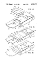
- FIGS. 4 through 6 are fragmentary isometric views of the easy opening, reclosable end of the carton showing successive steps in the closing of the end;
- FIG. 7 is a fragmentary perspective view of the easy opening, reclosable end of the carton after it has been opened and the weakened regions removed;
- FIG. 8 is a perspective view of the carton after it has been opened and reclosed
- FIG. 9 is a sectional view taken along the line 9--9 of FIG. 8;
- FIGS. 10, 11, 12 and 13 are views similar to FIGS. 1, 4, 7 and 8, but showing a second embodiment of the present invention.
- FIG. 14 is a fragmentary isometric view of the easy opening, reclosable end of a carton according to a third embodiment of the present invention prior to application of a separate insert to the carton;
- FIG. 15 is a fragmentary isometric view of the carton after application of the insert thereto;
- FIG. 16 is a fragmentary isometric view of the carton after it has been opened and reclosed, with the carton being shown in the open position in phantom line;
- FIG. 17 is a fragmentary isometric view of a carton according to a fourth embodiment of the present invention prior to sealing of the carton;
- FIG. 18 is a fragmentary isometric view of the carton after has been opened and the tab used to pivot outwardly the weakened region of the outer panel;
- FIG. 19 is a fragmentary isometric view of the carton after it has been reclosed.
- FIG. 1 illustrates a blank from which the carton 10 may be constructed.
- the carton 10 has the configuration of a rectangular parallelepiped and includes first, second, third and fourth side panels 14, 15, 16 and 17, a top end 19 and a bottom end 21 (only the first and second side panels 14, 15 and the top end 19 being visible in FIG. 2).
- the top end 19 is formed by first and third large end panels 24 and 26 (only first end panel 24 being visible in FIG. 2), and second and fourth small end panels 23 and 25 (only end panel 23 being visible in FIG. 2).
- the first and third side panels 14, 16 are referred to as major face panels, and the smaller second and fourth side panels 15, 17 are referred to as minor face panels.
- the first and third end panels 24 and 26 are referred to as major end panels, and the smaller second and fourth end panels 23, 25 are referred to as minor end panels.
- FIG. 2 only the major side panel 14, the minor side panel 15, the major end panel 24, and the minor end panel 23 are visible. Because the major end panel 24 lies over the major end panel 26 in a closed carton, the major end panel 24 is referred to as the outer or external major end panel while the major end panel 26 is referred to as the inner or internal major end panel. Similarly, because the minor end panel 23 overlies the major end panels 24, 26, it is referred to as the outer or external minor end panel, while the minor end panel 25 which lies under the major side panels 24, 26 is referred to as the internal or interior minor side panel.
- Each of the top end panels 23, 24, 25 and 26 is connected at a respective end thereof to side panels 15, 14, 17 and 16, respectively.
- Bottom end 21 is also formed by major and minor end panels (not shown in FIG. 2), but with both minor end panels underlying both major end panels so that there exists little likelihood of sifting.
- first end panel 24 is connected to first side panel 14
- second minor end panel 23 is connected to second minor side panel 15, etc.
- Carton 10 includes in its top end 19 a structure incorporating an easy opening feature and a reclosable feature as described in U.S. Pat. No. 4,718,557, the substance of which is hereby incorporated by reference.
- a tab or projection 28 of the external minor end panel 23, a weakened region 30 and opening 32 of internal major end panel 26 and a cut-away, open or weakened region 34 and a slit 36 of external major end panel 24 cooperate to provide the easy opening and reclosable features.
- Weakened region 30 of internal major end panel 26 (also referred to as a "flap") is defined by weakened portions illustrated by lines 40, which are at least partially cut through the panel, and by the edge of first side 41 of panel 26.
- the weakened portions illustrated by lines 40 are preferably formed by a nick cut in which the panel is fully cut through in the solid portions of lines and is not cut through in the broken portions of lines 40.
- the length of the uncut portions may be selected in accordance with the relative strength desired for weakened region 30 (or, conversely, the relative ease desired for severing weakened region 30).
- a weakened region 30 defined entirely by nick cut portions and panel edge 41 is presently preferred; however, weakened region 30 may also be formed by various combinations of weakened portions including perforations, kiss cuts, nick cuts and scoring, and panel edges, etc., so long as the major part of the weakened portions are at least partially cut through end panel 26 to facilitate at least partial severing of weakened region 30 from end panel 26.
- the weakened region 30 may be entirely removed from carton 10 during the manufacture thereof (and in fact during creation of the blank 12 therefor), albeit with a possible slight diminution in the sift-proof feature of the present invention a described hereinafter.
- Lines 40 extend from first side 41 of inner major end panel 26 inwardly thereof.
- line portions 40a and 40b extend at an angle to the opposed ends 43, 44 of the panel (i.e., generally diagonally) towards each other; however, portions 40a and 40b may also extend parallel to the opposed ends and to one another.
- One reason for extending line portions 40a and 40b at an angle to the panel ends, rather than parallel thereto, is that such diagonally extending weakened portions tear more easily than parallel weakened portions.
- Lines 40 include a third line portion 40c which extends transversely across inner major end panel 26 from line portion 40a to line portion 40b. Lines 40 defines a generally U shaped weakened portion.
- Line portion 40b extends from a point inwardly of the vertex of formed by the intersection of side 41 and end 44 of inner major end panel 26, while line portion 41a extends from a point inwardly of the vertex formed by the intersection of side 41 and end 43 of panel 26.
- unweakened region 45 in end panel 26 adjacent line 40a and an unweakened region 46 in end panel 26 adjacent line 40b.
- region 30 is completely severed from end panel 26 along lines 40, and an opening is created bounded by unweakened region 45 on one side and unweakened region 46 on the other side.
- external major end panel 24 includes a flap or weakened region 34, similar to the flap or weakened region 30 in internal major end panel 26.
- the weakened region 34 of external major end panel 24 is preferably slightly greater than in both length and width then the weakened region 30 of internal major end panel 26, although it may also be of the same size or even smaller in one or more of its dimensions.
- Weakened region 34 of external major end panel 26 is defined by weakened regions illustrated by lines 40, which are at least partially cut through the panel and by the edge or first side 41. Line portion 40c may be cut entirely through the panel 24 to leave the weakened region 34 secured to the panel 24 only at the sides thereof by lines 40a and 40b.
- line 41 of weakened region 34 differs in certain respects from line 41 of weakened region 30, as will be explained hereinafter in greater detail.
- line 41 of weakened region 34 represents a foldline or weakened line (for example, containing nick cut portions) or a combination thereof within external major end panel 24.
- FIG. 4 depicts carton 10 in its totally opened condition in which the various end panels 23, 24, 25, 26 are opened and extended.
- FIG. 5 depicts carton 10 in its partially closed condition in which internal minor end panel 25 has been folded first, then internal major end panel 26.
- FIG. 6 depicts carton 10 in a further closed condition in which the external major end panel 24 is folded over the internal major end panel 26.
- the weakened regions 30, 34 of the major end panels 26 and 24, respectively are located relative to each other on the respective panels so that when both are removed or displaced, an opening results through which the contents of the carton 10 may be poured out of the carton.
- external minor end panel 23 is folded over external major end panel 24 (and hence also over internal major end panel 26) as depicted in FIG. 2.
- Major end panels 24 and 26 are glued together, as will be described more fully in connection with the blank of FIG. 1, and external minor end panel 23 is glued to external major end panel 24 as discussed below.
- internal minor end panel 25 may be disposed intermediate major end panels 24 and 26, rather than below both; however, it should never be disposed above both panels, as this would interfere with the sift free feature of the present invention.
- glue is applied to panel 24 in discrete, separated, weakened regions 51, which are shaped as closed (e.g., circular) figures, and may be formed in the embodiment (see FIG. 6) by circular weakened portions in which end panel 24 has been partially cut through.
- Circular regions 51 may be located on external minor end panel 23 instead of or in addition to circular regions 51 on external major end panel 24.
- Opening of a sealed carton 10 is described with reference to FIG. 7.
- Outer minor end panel 23 is separated from the outer major end panel 24 by rasping tab 28 and pulling or lifting the tab 28. As discussed above, separation is facilitated by restricting glue to circular regions 51 so that any delamination occurs in separated circulated areas 51 on end panels 23 and 24.
- weakened regions 30 and 34 are pushed inwardly or pulled outwardly from major end panels 26 and 24, respectively, along lines 40 and optionally severed from the carton. (As illustrated in FIG. 9, weakened region 30 has been removed, but weakened region 34 has merely been pulled back.) This forms a generally wedge-shaped pour opening 56.
- the contents of carton 10 may be removed through opening 56, which is at the top of the carton. Opening 56 is, therefore, fully visible during pouring and "blind side" pouring is avoided.
- End panel 23 may also act as a pouring spout to assist in guiding the contents of the carton during pouring.
- weakened region 34 of outer major end panel 24 may be glued to outer minor end panel 23 so that it is torn away from the outer major end panel 24 and pulled back with the outer minor end panel 23 when outer minor end panel 23 is unsealed and pivoted open.
- outer minor end panel 23 is reclosed (i.e., disposed against outer major end panel 24) and tab 28 is inserted into slit 36 of outer major end panel 24. Opening 32 in inner major end panel 26, which is below slit 36, facilitates insertion of tab 28 into slit 36.
- Opening 32 in inner major end panel 26, which is below slit 36 facilitates insertion of tab 28 into slit 36.
- Structure other than tab 28, slit 36 and opening 32 may be used to interconnect outer minor end panel 23 to one of the other end panels.
- tab 28 may include a generally half moon projection or recess which facilitates grasping of the tab during the initial and subsequent openings of the carton.
- the weakened region 30 of the internal major side panel 26 may have one edge thereof defined not by nick cut portions, but rather by a foldline so that, when the weakened region 30 is pushed into the carton, it separates from the internal major end panel 26 along two sides, but not along the third side defined by the foldline. As a result, the weakened portion 30 will remain attached to the panel 26 within the carton.
- the outer major end panel 24 may include an edge portion or glue flap (not shown) which is glued to the major side panel 16 of the carton.
- Blank 60 may be glued and folded to form carton 10 of FIG. 2.
- Blank 60 is a one-piece blank made of a homogeneous sheet material, such as paperboard or the like, and includes weakened regions 62 shown as broken lines along which blank 60 may be folded.
- Weakened regions 62 are preferably score lines disposed to define first, second, third and fourth side panels 14, 15, 16 and 17; corresponding first, second, third and fourth top end panels 24, 23, 26 and 27; and corresponding bottom end panels 64, 65, 66 and 67.
- one weakened region 62 defines a glue panel or flap 70 which is connected to side panel 17.
- the solid lines in FIG. 1 within blank 60 represent cuts which form sides of the end panels.
- the reference numbers in FIG. 1 correspond to those in FIG. 2.
- Glue is conventionally applied to bottom end panels 64-67 and to glue flap 70. Glue is also applied to selected regions of the top end panels in order to provide the easy opening, reclosable features. Specifically, glue is applied to regions 74 and 75 of internal inner major end panel 26, to regions 51 of outer major end panel 24, and optionally to additional areas. Referring now to the sealed configuration of FIGS. 2-3, glue regions 74 and 75 of inner major end panel 26 are disposed on the top of end panel 26, and glue regions 51 are disposed on the top of outer major end panel 24.
- glue may be applied to inner minor end panel 25 or inner minor end panel 24 adjacent end panel 25, so that the top of inner minor end panel 25 will be glued to the bottom of inner major end panel 24.
- Major glue regions 74 and 75 are disposed between closed major end panels 22 and 24, and glue regions 51 are disposed between end panels 23 and 24.
- glue may be applied to the opposite facing panel surface rather than to the panel surfaces described above.
- Blank 60 may be glued and erected with standard folding carton machinery as follows. First, glue flap 70 is glued and adhered to major side panel 16 to form a flat knocked-down, partially assembled blank which may be shipped in that form to a location where it will be filled with product. Prior to erection of carton 10 for filling, glue is applied to regions 51, 74 and 75 (or glue previously applied to those regions is activated). Blank 60 is then folded along lines 62 to form a rectangular parallelepiped structure as depicted in FIG. 4, with top and bottom ends open. Thereafter, end panels 23, 24, 25 and 26 of top end 19 are folded as described in connection with FIGS. 4-6 and 2-3 and sealed together. The carton is then filled from the bottom end 21, and glue is applied to selected ones of the bottom end panels (or previously applied glue is activated). The bottom end panels are then closed and sealed conventionally. Blank 60 may also be glued and erected according to other procedures.
- the sift proof feature of the present invention may be obtained simply and without additional per carton cost simply by reducing the width of the outer minor end panel 23 (that is, the second end panel) relative to the width of the carton 10 and increasing the length of the outer major end panel 24 (that is, the first end panel) by some portion of that diminished width so that the length of the outer major end panel 24 exceeds the length of the major face panel 14 (that is, the first side panel) from which it extends.
- the excess length 100 is connected to the body of the outer major end panel 24 by the foldline 102 of what would otherwise be the edge or first side 41 of end panel 24. It will be appreciated that this excess length addition to the length of the outer major end panel 24 is achieved at the expense of the width of the outer minor end panel 23 and without incurring any additional per unit cost to the manufacturer in terms of either carton material or manufacturing process costs.
- the outer minor end panel 23 has width less than that of the carton 10 by at least the excess length 100.
- the width of the outer minor end panel 23 is less than that of one of the major end panels 24, 26 (and in particular the outer major end panel 24), and preferably less than that of either of the major end panels 24, 26. More particularly, the outer minor end panel 23 is spaced by at least the excess length 100 from the vertex or axis of intersection between the minor side panel 15 from which it extends and the adjacent major side panel 14.
- a portion of the opposite side of the outer minor end panel 23 may be cut away therefrom so that the panel 23 appears to be centered relative to the second minor side panel 15 from which it extends.
- At least one of the weakened regions 30 or 34 of major end panels 26 or 24 must be present in the sealed carton 10, preferably the weakened region 34 of the outer major end panel 24, and most preferably both. If desired, however, one of the weakened regions 30, 34, preferably the weakened region 30, may be absent from the sealed carton 10.
- the lowering of the outer minor end panel 23 onto the outer major end panel 24 causes the excess length 100 to become at least partially compacted and folded over and against the panel 24
- the bulk of the compacted and folded over portion of the excess length 100 acts as a barrier to the escape from the carton interior of any of the particulate matter which may have passed through the gap between the major end panels 24, 26 and the outer minor end panel 28.
- the free end 101 of the excess length 100 may be glued or otherwise secured to the outer minor end panel 23 during the closing and sealing operation (or previously applied glue activated).
- a region of glue may be provided on either the bottom of outer minor end panel 23 or the upper face of a portion of the free end 101 of excess length 100.
- the short portions of the excess length 100 extending to either side of the outer minor end panel 23 of the sealed carton 10 will assume and maintain the compacted and folded over configuration assumed by the intermediate portion of the excess length underlying the panel 23.
- the excess length 100 preferably extends the full width of the carton 10 (that is, is at least as wide as the overlapped width of the major end panels 24, 26), as illustrated in FIGS. 1-9, but it may be slightly less, as illustrated in FIGS. 10-13. In particular applications, the excess length 100 may even be of lesser width than the outer minor end panel 23, albeit with a possible diminution of the sift-free effect.
- the length of the excess length 100 is preferably just sufficient to cause the excess length to become at least partially folded over the outer major end panel 24 during the closing and sealing steps. Lengths of 5 to 20 millimeters have been found satisfactory although shorter and longer lengths may be used depending upon the materials employed, whether the excess length 100 will be secured to the outer minor end panel 23, and the like.
- the excess length 100 is a part of the outer major end panel 24 (or an extension thereof), alternatively the excess length 100 may be a part of the inner major end panel 26 (or an extension thereof). In this case, the excess length 100 must pass between the edge or first side of the outer major end panel 24 and the outer minor end panel 23 before being compacted and folded over the outer major end panel 24.
- a separate insert generally comparable to excess length 100 in size and configuration may be positioned between the panels 23 and 24 during the carton sealing step.
- This insert may be formed from the same material as the carton (and indeed created from the same blank 60) or from a different material.
- the insert may be loosely inserted into place during the sealing step so that, upon opening of the carton, it falls away from the carton.
- one end of the insert is glued to the panel 23 or 24 against which it will rest and, most preferably, each end of the insert is glued to the respective panel 23, 24 against which it will rest.
- the insert is adhered to major end panel 24, it effectively increases the length of panel 24 relative to the major side panel 14 from which it extends.
- the insert is conveniently formed of a pressure-sensitive label having a width comparable to that of the carton and a length sufficient to enable it to be adhered to both panels 23, 24.
- a major disadvantage of the use of such an insert is that at the least extra processing steps or equipment are required to position the insert within the carton being sealed and to adhere one or both ends of the insert to the panels 23 or 24. Additionally, if the insert is to be glued to either or both of the panels 23, 24, additional glue is required.
- FIGS. 10-13 therein illustrated is a second embodiment of the present invention, FIG. 10 showing the blank 60' and FIGS. 11-13 showing the carton 10' made from the blank 60'.
- the blank 60 and carton 10' are similar in all respects to the blank 60 and carton 10 of the first embodiment (illustrated in FIGS. 1 and 2-9, respectively), except in the following respects.
- the excess length 100 does not extend for the full width of inner major end panel 24, but rather extends only about half way between the edges 40a and 40b of the weakened region 34 and the adjacent edges 43, 44 of the outer major end panels 24. This results in only minor attenuation of the sift-proof feature of the present invention.
- the line 102 connecting the excess length 100 and the weakened region 104 is a fold line adjacent the weakened region or flap 34 and a nick cut or other line of severance adjacent the unweakened regions 45, 46 of outer major end panel 24.
- the flap 34 and the excess length 100 are removable together as a one piece integral unit from the carton 10' (as shown in FIG. 12).
- the carton is reclosed (as shown in FIG. 13) only the outer minor end panel 23 blocks the openings left by removal of the weakened regions of flaps 30 and 34.
- the sift-proof feature is destroyed. This is of little or no concern as, once the carton is in the consumer's home, sifting is not a problem because overturning of the carton is unlikely. Accordingly, at this point, the excess length 100 is unnecessary and may either be retained on the carton or removed therefrom and discarded, as desired. Referring to FIGS. 1-9, where it is desired to retain both the flap 34 and the excess length 100 in the opened carton, the line 102 may be a foldline for its entire extent.
- the line 102 may be nick cut between lines 40a and 40b so as to define a line of severance between the flap 34 and the excess length 100. In this instance, once the carton 10 is opened and flap 34 lifted, flap 34 is easily torn away from excess length 100 along line 102 and discarded. Referring to FIGS. 10-13, where it is desired instead to remove both flap 34 and the excess length 100, line 102 may be a foldline between lines 40a and 40b, but nick cut to define a line of severance between the excess length 100 and the unweakened regions 45, 46 on either side of the flap 34.
- the excess length 100 is attached to the carton (at unweakened regions 45, 46) only by means of nick cut portions of line 102.
- the composite flap 34/excess length 100 is easily torn away from the unweakened regions 45, 46 along line 102 and discarded, for example, with flap 30.
- the line 102 connecting the excess length 100 to the tab 34 and the unweakened regions 45, 46 of the outer major end panel 24 will be (a) a foldline for its entire length, or (b) a foldline adjacent the unweakened regions 45, 46 of panel 24 and a nick cut or other line of severance adjacent the flap 34, or (c) a foldline adjacent the flap 34 and a nick cut or other line of severance adjacent the unweakened regions 45, 46 of panel 24, respectively.
- FIGS. 14-16 therein illustrated is a third embodiment of the present invention in which a full width outer minor end panel 23 is employed.
- the carton 10" is in all respects identical tO that of U.S. Pat. No. 4,718,557, especially FIG. 3 thereof, except that the weakened regions 30, 34 thereof have been removed.
- a separate insert 120 is added to the carton 10".
- Insert 120 may be made of any thin, foldable, barrier providing material such as paper, foil, glassine, plastic film or the like.
- Insert 120 contains on one surface 122 thereof a glue or adhesive, preferably a pressure sensitive adhesive, so that end portions 124, 126 of the surface 122, on either side of a fold 130, can be adhered to the facing surfaces of outer major end panel 24 and outer minor end panel 23 in the closed carton.
- insert 120 may be devoid of adhesive and glue can be provided on the facing surfaces of panels 23, 24.
- the width of insert 120 is preferably equal in width to that of the carton and, in most instances, therefore equal to the full width of the outer major end panel 24.
- the insert 120 may, however, be of slightly lesser width than the carton, albeit with some attenuation of the sift-proof feature.
- the length of insert 120 is sufficient to enable one end portion 124 thereof to be secured to the outer minor end panel 23 and the other end portion 126 thereof to be secured to the outer major end panel 24, with the fold 130 between the end portions 124, 126 closing the gap between the two end panels 23, 24.
- the end portion 126 of insert 120 need only contact the upper portion of the outer major end panel 24 and need not extend further along the length thereof to cover its weakened region 34.
- the insert 120 becomes exposed and is easily removed from the carton, thereby leaving one or more of the weakened regions 30, 34 for removal, as with the prior embodiments.
- the weakened regions 30, 34 are preferably removed from the blank (or at least from the carton 10" prior to application of the insert 120) and the length of end portion 126 of insert 120 is sufficient to enable it to cover the resultant openings in the major side panels 24, 26.
- the insert 120 replaces both weakened regions 30, 34 and not only precludes sifting through the gap between the outer minor end panel 23 and the major end panels 24, 26, but also precludes sifting through the openings left in the major end panels 24, 26 by the removed weakened regions 30, 34.
- the insert 120 does not extend much beyond the weakened region 34 so as not to interfere with operation of the glued regions 51 or slit 36.
- the insert 120 need not be particularly strong, even if the weakened regions 30, 34 are removed, and may simply be a thin plastic film as the subsequent closure of the outer minor end panel 23 over the outer major end panel 24 affords all the necessary back up strength to the insert 120 required to enable it to perform its function. Removal of the insert 120 by the consumer exposes the aligned openings formed by removed weakened regions 30, 34 and so enables pouring from the interior of the carton.
- end portion 124 of insert 120 preferably remains attached to the outer minor end panel 23, as illustrated in FIG. 16 in phantom line, and only end portion 126 is manually lifted from the outer major end panel 24 to enable pouring. After pouring is completed, the lifted end portion 126 is returned to its original position across a portion of the outer major end panel 24, with the pressure-sensitive adhesive on surface 122 resealing with panel 24, as illustrated in FIG. 16 in solid line, thereby providing a barrier to sifting even for the reclosed carton in the consumer home.
- the insert 120 may be completely removed from the carton to facilitate unimpeded pouring of the particulate matter from the carton and then after pouring, if desired, replaced on the carton in its original position in order to once again render the carton sift proof.
- the insert 120 may be conveniently provided, at the end portion 126 thereof contacting the outer major end panel 24, with a thin marginal end strip or corner 123 which is devoid of glue or adhesive to facilitate lifting of that end 126 (as opposed to the opposite end 124 adhered to the outer minor end panel 23).
- the portion 125 of the insert 120 exposed to the contents of the carton, through the openings formed by removal of the weakened regions 30, 34, may be left devoid of glue or adhesive so that the contents of the carton do not adhere thereto and present to the consumer an impression of waste or contamination by the glue or adhesive.
- insert 120 is secured--e.g., by glue, adhesive or the like--to the outer major end panel 24, it acts as an integral part thereof forming the excess length by which the length of panel 24 exceeds the length of major side panel 14 from which it extends.
- insert 120 is completely covered by outer minor end panel 23 and is thus not visible prior to opening of the sealed carton.
- the two slits 36, 36 are aligned along the longitudinal axis of the carton end, but with the slit 36 in the outer major end panel 24 being longitudinally disposed closer to the adjacent minor side panel 15 (that is, closer to the vertex of the outer minor end panel 23 and the minor side panel 15 from which it extends) to facilitate passage of the tab 28 of the free end of the outer minor end panel 23 passing first through the slit 36 of the outer major end panel 24 and then through the slit 36' of the inner major end panel 26, as illustrated in FIG. 19.
- the longitudinal displacement of the two slits 36, 36' creates a tortuous path which is not conducive to sifting.
- the slit 36 on the outer major end panel 24 forms a flap 140 which must be depressed in order to allow the tab 28 of the outer minor end panel 23 to pass through the slit 36. Accordingly, it is preferred that the slit 36' of the inner major end panel 26 be slightly larger than the slit 36 of the outer major end panel 24 to facilitate displacement of the flap 140 (as well as tab 28) into the slit 36'.
- the excess length may be substantially less than the width of either the carton (that is, either of the major end panels 24, 26) or the weakened regions 30, 34 and may indeed constitute simply a tab 150 having a width substantially less than the width of the weakened region 30, 34.
- the tab 150 does not serve a sift free function, but rather constitutes only a means by which the weakened region 30, 34 to which it is attached may be easily and conveniently removed or pivoted away from its major end panel 26, 24, respectively. To this end, the tab 150 need only be of a sufficient size to enable it to be easily grasped and pulled by the user with sufficient strength to detach the weakened region from the carton or pivot it away.
- the tab 150 may conveniently be semicircular or half-moon in configuration and have a radius of about 0.25-0.50 inch (although a larger and more easily grasped tab 150 may be provided on a suitably wide carton).
- the line 102 is, between the tab 150 and the weakened region 30, 34, a fold line rather than a line of severance so that the tab 150 and weakened region 30, 34 are removable from the carton together as a unit.
- the tab 150 will generally not extend beyond the weakened region 30, 34, but, if for a particular application the tab 150 extends beyond the weakened regions 30, 34 so as to abut the unweakened regions 45, 46 of an end panel, the line -02 between the tab 150 and unweakened regions 45, 46 would either be a cut line or a line of severance.
- the tab 150 extends from the end of the weakened region 34 of the outer major end panel 24, as illustrated in FIGS. 17-19, so that the removal or pivoting of the weakened region 34 is facilitated.
- the weakened region 30 of the inner major end panel 26 will either have been removed during formation of the blank or may be easily pushed into or pulled out of the carton, once the outer weakened region 34 has been removed to expose the inner weakened region 30, during opening of the carton.
- the tab 150 may be disposed on the end of the weakened region 30 of the inner major end panel 26 so that, as the tab 150 is used to remove the inner weakened region 30, the inner weakened region 30 will carry with it the outer weakened region 34 so that all three elements --the inner and outer weakened regions 30, 34 and tab 150--are removed simultaneously from the carton. Whether or not the tab 150 and inner weakened region 30 are able to carry with them the outer weakened region 34 will depend on various factors including the ease of severance of the various weakened regions 30, 34 from their respective major end panels 26, 24, the strength of the attachment of the tab 150 to the inner weakened region 30, and the like.
- the tab 150 is similarly obtained at the expense of the outer minor end panel 23, thereby leaving at a minimum a corresponding half-moon or semicircular notch 152 in the outer minor end panel 23.
- a similar notch 52 may be placed at the other side of the outer minor end panel 23, the side of the outer minor end panel 23 which would otherwise bear the notch 152 may be cut away for its full length, or both sides of the outer minor panel 23 may be cut away for their entire lengths to the depths of what would otherwise be the notch 152 in order to present a more balanced appearance.
- the tab 150 extends from the end of the weakened region 30 of the inner major end panel 26 (rather than the weakened region 34 of the outer major end panel 24), the notch 152 is formed on the opposite side of the outer major end panel 23.
- the tab 150 may be used in connection with a non-sift-proof carton, a sift-proof carton having an excess length 100, or a sift proof carton having an insert 120.
- the tab 150 When used in a non-sift proof carton, the tab 150 is directly connected to the free end of the weakened region 30, 34.
- the tab 150 When used in a sift-proof carton having an excess length 100, the tab 150 is directly connected to the free end of the excess length 100 and provides a convenient means for removing the excess length 100 and weakened region 30, 34 to which it is attached by fold line 102, the tab 150 being especially useful when the excess length 100 is too short to facilitate grasping by the user.
- the tab 150 When used in a sift proof carton having an insert 120, the tab 150 is directly connected to the free end of the weakened region 30, 34 and is disposed in the unopened carton intermediate the outer minor end panel 23 and the insert 120 and becomes exposed for grasping when the insert 120 is lifted from the outer major end panel 24 and a portion of the outer minor end panel 23 sufficiently to expose the tab 150.
- the natural resilience of the paperboard or like material used to form the carton will be sufficient to cause the tab 150 to project outwardly from the carton, thus facilitating grasping thereof, once the outer minor end panel 23 and any insert 120 have been pivoted away therefrom sufficiently to expose and free the entire tab 150.
- weakened region refers to a region which is either connected to a panel by lines of severance so that it is easily removable from the panel or a region which has already been removed from the panel (typically during blank formation) and thus represents an opening.
- the excess length 100 is connected to a weakened region 30, 34
- the other weakened region 34, 30 may have been removed to define an opening.
- the insert 120 either one or both of the weakened regions 30, 34 may have been removed to define an opening or openings.
- the tab 150 is connected to a weakened region 30, 34 (either directly or via an excess length 100), the other weakened region 34, 30 may have been removed to define an opening.
- the present invention provides an easy opening, reclosable carton which is sift-resistant, and in a preferred embodiment substantially sift-proof, as well as a blank from which such a carton may be formed.
Landscapes
- Engineering & Computer Science (AREA)
- Mechanical Engineering (AREA)
- Cartons (AREA)
Abstract
Description
Claims (18)
Priority Applications (2)
| Application Number | Priority Date | Filing Date | Title |
|---|---|---|---|
| US07/344,972 US4941575A (en) | 1989-04-27 | 1989-04-27 | Sift-proof carton and blank therefor |
| US07/482,078 US4982846A (en) | 1989-04-27 | 1990-02-16 | Sift-proof carton and blank therefor |
Applications Claiming Priority (1)
| Application Number | Priority Date | Filing Date | Title |
|---|---|---|---|
| US07/344,972 US4941575A (en) | 1989-04-27 | 1989-04-27 | Sift-proof carton and blank therefor |
Related Child Applications (1)
| Application Number | Title | Priority Date | Filing Date |
|---|---|---|---|
| US07/482,078 Division US4982846A (en) | 1989-04-27 | 1990-02-16 | Sift-proof carton and blank therefor |
Publications (1)
| Publication Number | Publication Date |
|---|---|
| US4941575A true US4941575A (en) | 1990-07-17 |
Family
ID=23352900
Family Applications (1)
| Application Number | Title | Priority Date | Filing Date |
|---|---|---|---|
| US07/344,972 Expired - Fee Related US4941575A (en) | 1989-04-27 | 1989-04-27 | Sift-proof carton and blank therefor |
Country Status (1)
| Country | Link |
|---|---|
| US (1) | US4941575A (en) |
Cited By (4)
| Publication number | Priority date | Publication date | Assignee | Title |
|---|---|---|---|---|
| US5259552A (en) * | 1990-12-28 | 1993-11-09 | James River Corporation Of Virginia | Top panel spout carton |
| US5593030A (en) * | 1995-05-19 | 1997-01-14 | Tell; Richard B. | Compact disc holder |
| US5630504A (en) * | 1994-12-23 | 1997-05-20 | Fitzsimmons; W. Tyler | Compact disc package with plastic tray |
| GB2413549A (en) * | 2004-04-30 | 2005-11-02 | International Ltd Multibrands | Resealable box closure |
Citations (14)
| Publication number | Priority date | Publication date | Assignee | Title |
|---|---|---|---|---|
| US1956238A (en) * | 1933-10-16 | 1934-04-24 | William H Jackson | Dispensing carton |
| US2583856A (en) * | 1948-04-06 | 1952-01-29 | Charles G Klein | Lined dispensing carton |
| US3096011A (en) * | 1962-09-04 | 1963-07-02 | Sonoco Products Co | Container with pouring spout |
| US3155306A (en) * | 1961-11-01 | 1964-11-03 | Moore George Arlington | Premeasuring dispenser secured to leakproof container closure assembly |
| US3372853A (en) * | 1966-05-31 | 1968-03-12 | Brown Co | Dispensing carton having recloseable pour opening |
| US3426955A (en) * | 1966-09-16 | 1969-02-11 | Hoerner Waldorf Corp | Combination bag and box |
| US3477632A (en) * | 1967-06-08 | 1969-11-11 | Reynolds Metals Co | Dispensing container means and blanks for making same |
| US4258876A (en) * | 1978-04-17 | 1981-03-31 | Tetra Pak Developpement Sa | Reclosable pour opening structure for a packaging container and method of making same |
| US4317518A (en) * | 1980-09-04 | 1982-03-02 | Champion International Corporation | Carton with reclosable spout and blank therefor |
| US4548318A (en) * | 1983-10-31 | 1985-10-22 | Champion International Corporation | 3 Cell reclosable dispenser |
| US4613046A (en) * | 1984-06-28 | 1986-09-23 | James River Corporation | Reclosable package and carton blank |
| US4650078A (en) * | 1986-05-23 | 1987-03-17 | Container Corporation Of America | Carton with reclosable pouring opening |
| US4718557A (en) * | 1987-04-03 | 1988-01-12 | Ivy Hill Corporation | Easy opening, reclosable carton |
| DE3717805A1 (en) * | 1987-05-26 | 1988-12-08 | Edelmann Carl Gmbh | Tear-open package |
-
1989
- 1989-04-27 US US07/344,972 patent/US4941575A/en not_active Expired - Fee Related
Patent Citations (14)
| Publication number | Priority date | Publication date | Assignee | Title |
|---|---|---|---|---|
| US1956238A (en) * | 1933-10-16 | 1934-04-24 | William H Jackson | Dispensing carton |
| US2583856A (en) * | 1948-04-06 | 1952-01-29 | Charles G Klein | Lined dispensing carton |
| US3155306A (en) * | 1961-11-01 | 1964-11-03 | Moore George Arlington | Premeasuring dispenser secured to leakproof container closure assembly |
| US3096011A (en) * | 1962-09-04 | 1963-07-02 | Sonoco Products Co | Container with pouring spout |
| US3372853A (en) * | 1966-05-31 | 1968-03-12 | Brown Co | Dispensing carton having recloseable pour opening |
| US3426955A (en) * | 1966-09-16 | 1969-02-11 | Hoerner Waldorf Corp | Combination bag and box |
| US3477632A (en) * | 1967-06-08 | 1969-11-11 | Reynolds Metals Co | Dispensing container means and blanks for making same |
| US4258876A (en) * | 1978-04-17 | 1981-03-31 | Tetra Pak Developpement Sa | Reclosable pour opening structure for a packaging container and method of making same |
| US4317518A (en) * | 1980-09-04 | 1982-03-02 | Champion International Corporation | Carton with reclosable spout and blank therefor |
| US4548318A (en) * | 1983-10-31 | 1985-10-22 | Champion International Corporation | 3 Cell reclosable dispenser |
| US4613046A (en) * | 1984-06-28 | 1986-09-23 | James River Corporation | Reclosable package and carton blank |
| US4650078A (en) * | 1986-05-23 | 1987-03-17 | Container Corporation Of America | Carton with reclosable pouring opening |
| US4718557A (en) * | 1987-04-03 | 1988-01-12 | Ivy Hill Corporation | Easy opening, reclosable carton |
| DE3717805A1 (en) * | 1987-05-26 | 1988-12-08 | Edelmann Carl Gmbh | Tear-open package |
Cited By (4)
| Publication number | Priority date | Publication date | Assignee | Title |
|---|---|---|---|---|
| US5259552A (en) * | 1990-12-28 | 1993-11-09 | James River Corporation Of Virginia | Top panel spout carton |
| US5630504A (en) * | 1994-12-23 | 1997-05-20 | Fitzsimmons; W. Tyler | Compact disc package with plastic tray |
| US5593030A (en) * | 1995-05-19 | 1997-01-14 | Tell; Richard B. | Compact disc holder |
| GB2413549A (en) * | 2004-04-30 | 2005-11-02 | International Ltd Multibrands | Resealable box closure |
Similar Documents
| Publication | Publication Date | Title |
|---|---|---|
| CA2102792C (en) | Reclosable carton for granular materials | |
| US5123589A (en) | Reusable rigid film pack | |
| CA1209551A (en) | Reclosable carton | |
| US5511722A (en) | Reclosable flip-top carton | |
| US3768719A (en) | Carton having a bag-like liner | |
| US5860526A (en) | Apparatus and method for retaining a cylindrical shaped product or container within a shadow carton so that the front label on the product or container does not rotate out of view | |
| US4591091A (en) | Aseptic container with tamper-resistant spout and blank therefor | |
| EP0392737A1 (en) | Freshness-preserving container | |
| JPH08502228A (en) | Box with hinged lid with pop-out coupons connected | |
| US5678755A (en) | Paperboard carton having a pour spout and blank for forming the same | |
| US5445316A (en) | Sift proof and tamper evident pouring spout | |
| US5326024A (en) | Carton with reclosable pouring opening | |
| AU678523B2 (en) | Corner with reclosable corner pour opening | |
| US5238181A (en) | Container with integral pouring spout and method of manufacture | |
| EP0588789B1 (en) | Carton for granular materials | |
| US4127229A (en) | Flip top dispenser box | |
| US4718557A (en) | Easy opening, reclosable carton | |
| US4441612A (en) | Easy open carton | |
| US4982846A (en) | Sift-proof carton and blank therefor | |
| US4941575A (en) | Sift-proof carton and blank therefor | |
| US4524870A (en) | Visible and easy accessible package | |
| US5007542A (en) | Recloseable carton with pouring spout | |
| US5002222A (en) | Carton with closure | |
| EP1145974A1 (en) | Package for food products, blank of a package for food products and method of manufacturing such a blank | |
| US3469767A (en) | Box and box blank |
Legal Events
| Date | Code | Title | Description |
|---|---|---|---|
| AS | Assignment |
Owner name: IVY HILL CORPORATION, A CORP. OF DE, NEW YORK Free format text: ASSIGNMENT OF ASSIGNORS INTEREST.;ASSIGNOR:FRIEDMAN, HERBERT;REEL/FRAME:005068/0141 Effective date: 19890424 |
|
| REMI | Maintenance fee reminder mailed | ||
| LAPS | Lapse for failure to pay maintenance fees | ||
| FP | Lapsed due to failure to pay maintenance fee |
Effective date: 19940720 |
|
| AS | Assignment |
Owner name: WACHOVIA BANK, NATIONAL ASSOCIATION, NORTH CAROLIN Free format text: SECURITY AGREEMENT;ASSIGNOR:MPS/IH, LLC;REEL/FRAME:022529/0688 Effective date: 20090409 |
|
| AS | Assignment |
Owner name: WACHOVIA BANK, NATIONAL ASSOCIATION, NORTH CAROLIN Free format text: SECURITY AGREEMENT;ASSIGNOR:MPS/IH, LLC;REEL/FRAME:022542/0090 Effective date: 20090409 |
|
| AS | Assignment |
Owner name: MPS/IH, LLC, MICHIGAN Free format text: NOTICE OF SATISFACTION OF 2ND LIEN IP SECURITY AGREEMENT;ASSIGNOR:WELLS FARGO BANK, NATIONAL ASSOCIATION (SUCCESSOR BY MERGER TO WACHOVIA BANK, NATIONAL ASSOCIATION);REEL/FRAME:024812/0626 Effective date: 20100513 Owner name: MPS/IH, LLC, MICHIGAN Free format text: NOTICE OF SATISFACTION OF 1ST LIEN IP SECURITY AGREEMENT;ASSIGNOR:WELLS FARGO BANK, NATIONAL ASSOCIATION (SUCCESSOR BY MERGER TO WACHOVIA BANK, NATIONAL ASSOCIATION);REEL/FRAME:024812/0742 Effective date: 20100513 |
|
| STCH | Information on status: patent discontinuation |
Free format text: PATENT EXPIRED DUE TO NONPAYMENT OF MAINTENANCE FEES UNDER 37 CFR 1.362 |